dienelectrics@gmail.com
 0909186879 dienelectrics@gmail.com
 2,854
2,854


| Product | ||||||||||||||||||||||||||||||||||||||||
| Article Number (Market Facing Number) | 6SL32101PE218UL0 | 6SL32101PE218UL0 | |||||||||||||||||||||||||||||||||||||||
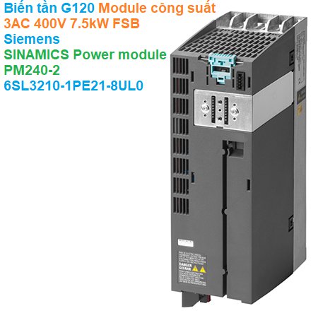
| Product Description | SINAMICS POWER MODULE PM240-2 WITHOUT FILTER WITH BUILT IN BRAKING CHOPPER 3AC380-480V +10/-10% 47-63HZ OUTPUT HIGH OVERLOAD: 5,5KW FOR 200% 3S,150% 57S,100% 240S AMBIENT TEMP -10 TO +50 DEG C OUTPUT LOW OVERLOAD: 7,5KW FOR 150% 3S,110% 57S,100% 240S AMBIENT TEMP -10 TO +40 DEG C 291 X 100 X 165 (HXWXD), FSB PROTECTION IP20 WITHOUT CONTROL UNIT AND PANEL APPROVED FOR CU FIRMWARE- VERSION V4.6 | |||||||||||||||||||||||||||||||||||||||
| Product family | Ordering Data Overview | |||||||||||||||||||||||||||||||||||||||
| Product Lifecycle (PLM) | PM300:Active Product | |||||||||||||||||||||||||||||||||||||||
| Price data | ||||||||||||||||||||||||||||||||||||||||
| Price Group | 975 | |||||||||||||||||||||||||||||||||||||||
| List Price | Show prices | |||||||||||||||||||||||||||||||||||||||
| Customer Price | Show prices | |||||||||||||||||||||||||||||||||||||||
| Metal Factor | None | |||||||||||||||||||||||||||||||||||||||
| Delivery information | ||||||||||||||||||||||||||||||||||||||||
| Export Control Regulations | AL : N / ECCN : 3A999A | |||||||||||||||||||||||||||||||||||||||
| Standard lead time ex-works | 3 Day/Days | |||||||||||||||||||||||||||||||||||||||
| Net Weight (lb) | 6.614 lb | |||||||||||||||||||||||||||||||||||||||
| Product Dimensions (W x L x H) | Not available | |||||||||||||||||||||||||||||||||||||||
| Packaging Dimension | 14.567 x 7.087 x 4.724 | |||||||||||||||||||||||||||||||||||||||
| Package size unit of measure | in | |||||||||||||||||||||||||||||||||||||||
| Quantity Unit | 1 Piece | |||||||||||||||||||||||||||||||||||||||
| Packaging Quantity | 1 | |||||||||||||||||||||||||||||||||||||||
| Additional Product Information | ||||||||||||||||||||||||||||||||||||||||
| EAN | 4042948666081 | |||||||||||||||||||||||||||||||||||||||
| UPC | 887621708542 | |||||||||||||||||||||||||||||||||||||||
| Commodity Code | 85044084 | |||||||||||||||||||||||||||||||||||||||
| LKZ_FDB/ CatalogID | D11.1SD | |||||||||||||||||||||||||||||||||||||||
| Product Group | 9772 | |||||||||||||||||||||||||||||||||||||||
| Country of origin | Great Britain | |||||||||||||||||||||||||||||||||||||||
| Compliance with the substance restrictions according to RoHS directive | Since: 07/01/2006 | |||||||||||||||||||||||||||||||||||||||
| Returnable | Yes | |||||||||||||||||||||||||||||||||||||||
| WEEE (2012/19/EU) Take-Back Obligation | Yes | |||||||||||||||||||||||||||||||||||||||
| Classifications | ||||||||||||||||||||||||||||||||||||||||
|
||||||||||||||||||||||||||||||||||||||||
.png)
.png)
|
Frame size |
|||||||
|---|---|---|---|---|---|---|---|
|
|
FSA |
FSB |
FSC |
FSD |
FSE |
FSF |
FSG |
|
PM240‑2 Power Module with integrated braking chopper |
|||||||
|
Available frame sizes |
|
|
|
|
|
|
|
|
✓ |
✓ |
✓ |
✓ 1) |
✓ 1) |
✓ 1) |
– |
|
✓ |
✓ |
✓ |
✓ |
✓ |
✓ |
✓ |
|
– |
– |
– |
✓ 2) |
✓ 2) |
✓ |
✓ |
|
Line-side components |
|||||||
|
Line filter class A |
F |
F |
F |
F 1) |
F 1) |
F 1) |
– |
|
Line filter class B (only for 400 V versions) |
U 3) |
U 3) |
U 3) |
– |
– |
– |
– |
|
Line filters Category C2 or C3 (for 400 V versions frame size FSG) |
– |
– |
– |
– |
– |
– |
I |
|
Line filters Category C3 (for 690 V versions frame size FSG) |
– |
– |
– |
– |
– |
– |
I 4) |
|
Line reactor (only for 3 AC versions 5)) |
S 6) |
S 6) |
S 6) |
I |
I |
I |
I |
|
DC link components |
|||||||
|
Braking resistor |
S |
S |
S |
S |
S |
S |
S |
|
Load-side power components |
|||||||
|
Output reactor |
S |
S |
S |
S 2) |
S 2) |
S |
S |
|
dv/dt filter plus VPL (for 400 V and 690 V versions only 9)) |
S |
S |
S |
S |
S |
S |
S |
-a-Control-Unit-(CU)-and-base-components-(side-view).png)
|
Power Module |
Base |
Lateral mounting |
|
|---|---|---|---|
|
Frame size |
|
Left of the converter |
Right of the converter |
|
FSA and FSB |
Line filter |
Line reactor |
Output reactor or |
|
FSC |
Line filter 1) |
Line reactor |
Output reactor or |
|
FSD and FSE |
– |
Line filter |
Output reactor or |
|
FSF and FSG |
– |
Line filter |
Output reactor or |
|
Maximum permissible motor cable lengths (shielded/unshielded) in m (ft) |
|||||||
|---|---|---|---|---|---|---|---|
|
Frame size |
FSA |
FSB |
FSC |
FSD |
FSE |
FSF |
FSG |
|
PM240‑2 Power Module with integrated braking chopper |
|||||||
|
Without optional power components |
|
|
|
|
|
|
|
|
50/100 (164/328) |
50/100 (164/328) |
50/100 (164/328) |
200/300 (656/984) |
200/300 (656/984) |
300/450 (984/1476) |
– |
|
50/100 (164/328) |
50/100 (164/328) |
50/100 (164/328) |
– |
– |
– |
– |
|
150/150 (492/492) |
150/150 (492/492) |
150/150 (492/492) |
200/300 (656/984) |
200/300 (656/984) |
300/450 (984/1476) |
300/450 (984/1476) |
|
50/100 (164/328) |
100/100 1)(328/328) 1) |
150/150 1)(492/492) 1) |
200/300 (656/984) |
200/300 (656/984) |
300/450 (984/1476) |
300/450 (984/1476) |
|
– |
– |
– |
200/300 (656/984) |
200/300 (656/984) |
300/450 (984/1476) |
300/450 (984/1476) |
|
With optional output reactor |
|
|
|
|
|
|
|
|
150/225 (492/738) |
150/225 (492/738) |
150/225 (492/738) |
200/300 (656/984) 2) |
200/300 (656/984) 2) |
300/450 (984/1476) 2) |
– |
|
150/225 (492/738) |
150/225 (492/738) |
150/225 (492/738) |
200/300 (656/984) 2) |
200/300 (656/984) 2) |
300/450 (984/1476) 2) |
300/450 (984/1476) 2) |
|
100/150 (328/492) |
100/150 (328/492) |
100/150 (328/492) |
200/300 (656/984) 2) |
200/300 (656/984) 2) |
300/450 (984/1476) 2) |
300/450 (984/1476) 2) |
|
– |
– |
– |
200/300 (656/984) 2) |
200/300 (656/984) 2) |
300/450 (984/1476) 2) |
300/450 (984/1476) 2) |
|
With optional dv/dt filter plus VPL |
|
|
|
|
|
|
|
|
350/525 (1148/1723) |
350/525 (1148/1723) |
350/525 (1148/1723) |
30 kW: 350/525 (1148/1723) 37 kW: 450/650 (1476/2133) 3) |
450/650 (1476/2133) 3) |
450/650 (1476/2133) 3) |
– |
|
– |
– |
– |
350/525 (1148/1723) |
350/525 (1148/1723) |
450/650 (1476/2133) 3) |
450/650 (1476/2133) 3) |
|
With integrated line filter According to EN 55011 to comply with radio interference emissions according to EN 61800‑3 EMC Category C2 |
|
|
|
|
|
|
|
|
50/– (164/–) |
50/– (164/–) |
50/– (164/–) |
– |
– |
– |
– |
|
50/– (164/–) |
100/– (328/–) 4) |
150/– (492/–) 4) |
150/– (492/–) |
150/– (492/–) |
150/– (492/–) |
150/– (492/–) (Category C2) 300 /– (984/–) (Category C3) |
|
– |
– |
– |
100/– (328/–) |
100/– (328/–) |
150 /– (492/–) (Category C3) |
300 /– (984/–) (Category C3 5)) |
|
With optional, external line filter class B According to EN 55011 to comply with conducted radio interference emissions according to EN 61800‑3 EMC Category C1 6), together with unfiltered Power Module |
|
|
|
|
|
|
|
|
50/– (164/–) |
50/– (164/–) |
50/– (164/–) |
– |
– |
– |
– |
|
With optional, external line filter class B According to EN 55011 and optional output reactor to comply with radio interference emissions according to EN 61800‑3 EMC Category C2 6), together with unfiltered Power Module |
|
|
|
|
|
|
|
|
150/– (492/–) |
150/– (492/–) |
150/– (492/–) |
– |
– |
– |
– |
|
100/– (328/–) |
100/– (328/–) |
100/– (328/–) |
– |
– |
– |
– |
|
Power Modules |
PM240‑2 |
|---|---|
|
System operating voltage |
FSA ... FSC: FSD ... FSG: |
|
Line supply requirements |
200 V: >25 With RSC >50 it is advisable for FSA to FSC to install a line reactor, or alternatively, to select a Power Module with the next-higher power rating. 400 V: >25 With RSC >100 it is advisable for FSA to FSC to install a line reactor, or alternatively, to select a Power Module with the next-higher power rating. 690 V: No restriction |
|
Input frequency |
47 ... 63 Hz |
|
Output frequency |
|
|
0 ... 550 Hz |
|
0 ... 240 Hz |
|
Pulse frequency |
200 V: 4 kHz 400 V: ≤55 kW: 4 kHz; ≥75 kW: 2 kHz 690 V: 2 kHz For higher pulse frequencies, see derating data |
|
Power factor λ |
FSA ... FSC: FSD ... FSG: |
|
Offset factor cos φ |
FSA ... FSC: >0.96 FSD ... FSG: 0.98 ... 0.99 |
|
Converter efficiency |
200 V: >96 % 400 V: >97 % 690 V: >98 % |
|
Output voltage, max. as % of input voltage |
95 % |
|
Overload capability |
|
Note: No reduction in base-load current IL for use of overload. |
1.5 × base-load current IL (i.e. 150 % overload) for 3 s plus 1.1 × base-load current IL (i.e. 110 % overload) for 57 s within a cycle time of 300 s |
Note: No reduction in base-load current IL for use of overload. |
2 × base-load current IH (i.e. 200 % overload) for 3 s plus 1.5 × base-load current IH (i.e. 150 % overload) for 57 s within a cycle time of 300 s |
|
Possible braking methods |
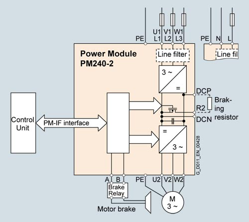
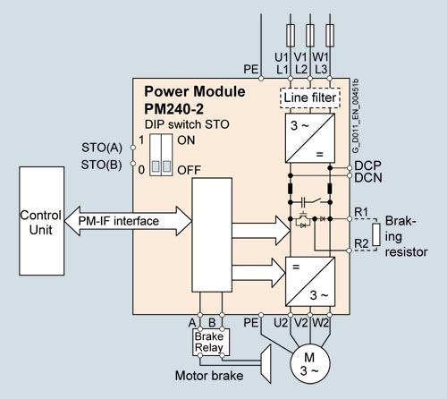
DC braking Compound braking Dynamic braking with integrated braking chopper |
|
Degree of protection |
IP20 (standard or push-through) |
|
Operating temperature |
|
|
Frame sizes FSA ... FSC: Frame sizes FSD ... FSG: |
|
Frame sizes FSA ... FSC: Frame sizes FSD ... FSG: |
|
Relative humidity |
< 95 % RH, condensation not permissible |
|
Cooling |
Internal air cooling, power units with increased air cooling by built-in fans |
|
Installation altitude |
Up to 1000 m (3281 ft) above sea level without derating, |
|
Protection functions |
|
|
Short-Circuit Current Rating SCCR according to UL |
200 V: 100 kA 400 V: 100 kA 690 V: 100 kA |
|
Compliance with standards |
CE, cULus, RCM, SEMI F47, RoHS, EAC, KC (only with internal or external line filters Category C2) For frame size FSD ... FSG also: WEEE (Waste Electrical & Electronic Equipment) |
|
CE marking |
According to Low Voltage Directive 2014/35/EU, EMC Directive 2014/30/EU |
1) Applies to industrial control panel installations to NEC article 409 or UL 508A.
|
Line voltage 200 ... 240 V 1 AC/3 AC |
PM240‑2 Power Modules standard variant |
|||||
|---|---|---|---|---|---|---|
|
Without integrated line filter |
6SL3210-1PB13-0UL0 |
6SL3210-1PB13-8UL0 |
6SL3210-1PB15-5UL0 |
6SL3210-1PB17-4UL0 |
6SL3210-1PB21-0UL0 |
|
|
With integrated line filter class A |
6SL3210-1PB13-0AL0 |
6SL3210-1PB13-8AL0 |
6SL3210-1PB15-5AL0 |
6SL3210-1PB17-4AL0 |
6SL3210-1PB21-0AL0 |
|
|
Output current at 50 Hz 230 V 1 AC |
|
|
|
|
|
|
|
A |
3.2 |
4.2 |
6 |
7.4 |
10.4 |
|
A |
3.2 |
4.2 |
6 |
7.4 |
10.4 |
|
A |
2.3 |
3.2 |
4.2 |
6 |
7.4 |
|
A |
4.6 |
6 |
8.3 |
11.1 |
15.6 |
|
Rated power |
|
|
|
|
|
|
|
kW (hp) |
0.55 (0.75) |
0.75 (1) |
1.1 (1.5) |
1.5 (2) |
2.2 (3) |
|
kW (hp) |
0.37 (0.50) |
0.55 (0.75) |
0.75 (1) |
1.1 (1.5) |
1.5 (2) |
|
Rated pulse frequency |
kHz |
4 |
4 |
4 |
4 |
4 |
|
Efficiency η |
% |
>96 |
>96 |
>96 |
>96 |
>96 |
|
Power loss 3) At rated current |
kW |
0.04 |
0.04 |
0.05 |
0.07 |
0.12 |
|
Cooling air requirement |
m3/s (ft3/s) |
0.005 (0.18) |
0.005 (0.18) |
0.0092 (0.325) |
0.0092 (0.325) |
0.0092 (0.325) |
|
Sound pressure level LpA (1 m) |
dB |
<50 |
<50 |
<62 |
<62 |
<62 |
|
Input current 4) |
|
|
|
|
|
|
|
A |
7.5/4.2 |
9.6/5.5 |
13.5/7.8 |
18.1/9.7 |
24/13.6 |
|
A |
6.6/3 |
8.4/4.2 |
11.8/5.5 |
15.8/7.8 |
20.9/9.7 |
|
Line supply connection U1/L1, V1/L2, W1/L3 |
|
Terminal connector |
Terminal connector |
Terminal connector |
Terminal connector |
Terminal connector |
|
mm2 |
1.5 ... 2.5 |
1.5 ... 2.5 |
1.5 ... 6 |
1.5 ... 6 |
1.5 ... 6 |
|
Motor connection U2, V2, W2 |
|
Terminal connector |
Terminal connector |
Terminal connector |
Terminal connector |
Terminal connector |
|
mm2 |
1.5 ... 2.5 |
1.5 ... 2.5 |
1.5 ... 6 |
1.5 ... 6 |
1.5 ... 6 |
|
PE connection |
|
Included in terminal connector |
Included in terminal connector |
Included in terminal connector |
Included in terminal connector |
Included in terminal connector |
|
Motor cable length, max. |
|
|
|
|
|
|
|
m (ft) |
50 (164) |
50 (164) |
50 (164) |
50 (164) |
50 (164) |
|
m (ft) |
100 (328) |
100 (328) |
100 (328) |
100 (328) |
100 (328) |
|
Degree of protection |
|
IP20 |
IP20 |
IP20 |
IP20 |
IP20 |
|
Dimensions |
|
|
|
|
|
|
|
mm (in) |
73 (2.87) |
73 (2.87) |
100 (3.94) |
100 (3.94) |
100 (3.94) |
|
mm (in) |
196 (7.72) |
196 (7.72) |
292 (11.5) |
292 (11.5) |
292 (11.5) |
|
|
|
|
|
|
|
|
mm (in) |
165 (6.50) |
165 (6.50) |
165 (6.50) |
165 (6.50) |
165 (6.50) |
|
mm (in) |
238 (9.37) |
238 (9.37) |
238 (9.37) |
238 (9.37) |
238 (9.37) |
|
Frame size |
|
FSA |
FSA |
FSB |
FSB |
FSB |
|
Weight, approx. |
|
|
|
|
|
|
|
kg (lb) |
1.4 (3.09) |
1.4 (3.09) |
2.8 (6.17) |
2.8 (6.17) |
2.8 (6.17) |
|
kg (lb) |
1.6 (3.53) |
1.6 (3.53) |
3.1 (6.84) |
3.1 (6.84) |
3.1 (6.84) |
1) The rated output current Irated and the base-load current IL are based on the duty cycle for low overload (LO).
2) The base-load current IH is based on the duty cycle for high overload (HO).
3) Typical values. You can find more information on the Internet at:
- https://support.industry.siemens.com/cs/document/94059311
4) The input current depends on the motor load and line impedance. The input currents apply for a load at rated power (based on Irated) for a line impedance corresponding to uK = 1 %. The current values are specified on the rating plate of the Power Module.
|
Line voltage 200 ... 240 V 1 AC/3 AC |
PM240‑2 Power Modules standard variant |
||
|---|---|---|---|
|
Without integrated line filter |
6SL3210-1PB21-4UL0 |
6SL3210-1PB21-8UL0 |
|
|
With integrated line filter class A |
6SL3210-1PB21-4AL0 |
6SL3210-1PB21-8AL0 |
|
|
Output current at 50 Hz 230 V 1 AC |
|
|
|
|
A |
13.6 |
17.5 |
|
A |
13.6 |
17.5 |
|
A |
10.4 |
13.6 |
|
A |
20.8 |
27.2 |
|
Rated power |
|
|
|
|
kW (hp) |
3 (4) |
4 (5) |
|
kW (hp) |
2.2 (3) |
3 (4) |
|
Rated pulse frequency |
kHz |
4 |
4 |
|
Efficiency η |
% |
>96 |
>96 |
|
Power loss 3) At rated current |
kW |
0.14 |
0.18 |
|
Cooling air requirement |
m3/s (ft3/s) |
0.0185 (0.65) |
0.0185 (0.65) |
|
Sound pressure level LpA (1 m) |
dB |
<65 |
<65 |
|
Input current 4) |
|
|
|
|
A |
35.9/17.7 |
43/22.8 |
|
A |
31.3/13.6 |
37.5/17.7 |
|
Line supply connection U1/L1, V1/L2, W1/L3 |
|
Terminal connector |
Terminal connector |
|
mm2 |
6 ... 16 |
6 ... 16 |
|
Motor connection U2, V2, W2 |
|
Terminal connector |
Terminal connector |
|
mm2 |
6 ... 16 |
6 ... 16 |
|
PE connection |
|
Included in terminal connector |
Included in terminal connector |
|
Motor cable length, max. |
|
|
|
|
m (ft) |
50 (164) |
50 (164) |
|
m (ft) |
100 (328) |
100 (328) |
|
Degree of protection |
|
IP20 |
IP20 |
|
Dimensions |
|
|
|
|
mm (in) |
140 (5.51) |
140 (5.51) |
|
mm (in) |
355 (13.98) |
355 (13.98) |
|
|
|
|
|
mm (in) |
165 (6.50) |
165 (6.50) |
|
mm (in) |
238 (9.37) |
238 (9.37) |
|
Frame size |
|
FSC |
FSC |
|
Weight, approx. |
|
|
|
|
kg (lb) |
5 (11) |
5 (11) |
|
kg (lb) |
5.2 (11.5) |
5.2 (11.5) |
1) The rated output current Irated and the base-load current IL are based on the duty cycle for low overload (LO).
2) The base-load current IH is based on the duty cycle for high overload (HO).
3) Typical values. You can find more information on the Internet at:
- https://support.industry.siemens.com/cs/document/94059311
4) The input current depends on the motor load and line impedance. The input currents apply for a load at rated power (based on Irated) for a line impedance corresponding to uK = 1 %. The current values are specified on the rating plate of the Power Module.
|
Line voltage 200 ... 240 V 3 AC |
PM240‑2 Power Modules standard variant |
|||||
|---|---|---|---|---|---|---|
|
Without integrated line filter |
6SL3210-1PC22-2UL0 |
6SL3210-1PC22-8UL0 |
6SL3210-1PC24-2UL0 |
6SL3210-1PC25-4UL0 |
6SL3210-1PC26-8UL0 |
|
|
With integrated line filter class A |
6SL3210-1PC22-2AL0 |
6SL3210-1PC22-8AL0 |
– |
– |
– |
|
|
Output current at 50 Hz 230 V 3 AC |
|
|
|
|
|
|
|
A |
22 |
28 |
42 |
54 |
68 |
|
A |
22 |
28 |
42 |
54 |
68 |
|
A |
17.5 |
22 |
35 |
42 |
54 |
|
A |
35 |
44 |
70 |
84 |
108 |
|
Rated power |
|
|
|
|
|
|
|
kW (hp) |
5.5 (7.5) |
7.5 (10) |
11 (15) |
15 (20) |
18.5 (25) |
|
kW (hp) |
4 (5) |
5.5 (7.5) |
7.5 (10) |
11 (15) |
15 (20) |
|
Rated pulse frequency |
kHz |
4 |
4 |
4 |
4 |
4 |
|
Efficiency η |
% |
>97 |
>97 |
>97 |
>97 |
>97 |
|
Power loss 3) At rated current |
kW |
0.2 |
0.26 |
0.45 |
0.61 |
0.82 |
|
Cooling air requirement |
m3/s (ft3/s) |
0.0185 (0.65) |
0.0185 (0.65) |
0.055 (1.94) |
0.055 (1.94) |
0.055 (1.94) |
|
Sound pressure level LpA (1 m) |
dB |
<65 |
<65 |
45 ... 65 4) |
45 ... 65 4) |
45 ... 65 4) |
|
Input current 5) |
|
|
|
|
|
|
|
A |
28.6 |
36.4 |
40 |
51 |
64 |
|
A |
22.8 |
28.6 |
36 |
43 |
56 |
|
Line supply connection U1/L1, V1/L2, W1/L3 |
|
Terminal connector |
Terminal connector |
Screw terminals |
Screw terminals |
Screw terminals |
|
mm2 |
6 ... 16 |
6 ... 16 |
10 ... 35 |
10 ... 35 |
10 ... 35 |
|
Motor connection U2, V2, W2 |
|
Terminal connector |
Terminal connector |
Screw terminals |
Screw terminals |
Screw terminals |
|
mm2 |
6 ... 16 |
6 ... 16 |
10 ... 35 |
10 ... 35 |
10 ... 35 |
|
PE connection |
|
Included in terminal connector |
Included in terminal connector |
Screw terminals |
Screw terminals |
Screw terminals |
|
Motor cable length, max. |
|
|
|
|
|
|
|
m (ft) |
50 (164) |
50 (164) |
200 (656) |
200 (656) |
200 (656) |
|
m (ft) |
100 (328) |
100 (328) |
300 (984) |
300 (984) |
300 (984) |
|
Degree of protection |
|
IP20 |
IP20 |
IP20 |
IP20 |
IP20 |
|
Dimensions |
|
|
|
|
|
|
|
mm (in) |
140 (5.51) |
140 (5.51) |
200 (7.87) |
200 (7.87) |
200 (7.87) |
|
mm (in) |
355 (13.98) |
355 (13.98) |
472 (18.58) |
472 (18.58) |
472 (18.58) |
|
|
|
|
|
|
|
|
mm (in) |
165 (6.50) |
165 (6.50) |
237 (9.33) |
237 (9.33) |
237 (9.33) |
|
mm (in) |
238 (9.37) |
238 (9.37) |
268 (10.55) |
268 (10.55) |
268 (10.55) |
|
Frame size |
|
FSC |
FSC |
FSD |
FSD |
FSD |
|
Weight, approx. |
|
|
|
|
|
|
|
kg (lb) |
5 (11) |
5 (11) |
17 (37.5) |
17 (37.5) |
17 (37.5) |
|
kg (lb) |
5.2 (11.5) |
5.2 (11.5) |
– |
– |
– |
1) The rated output current Irated and the base-load current IL are based on the duty cycle for low overload (LO).
2) The base-load current IH is based on the duty cycle for high overload (HO).
3) Typical values. You can find more information on the Internet at:
- https://support.industry.siemens.com/cs/document/94059311
4) Values dependent on ambient temperature and utilization.
5) The input current depends on the motor load and line impedance. The input currents apply for a load at rated power (based on Irated) for a line impedance corresponding to uK = 1 %. The current values are specified on the rating plate of the Power Module.
|
Line voltage 200 ... 240 V 3 AC |
PM240‑2 Power Modules standard variant |
|||||
|---|---|---|---|---|---|---|
|
Without integrated line filter |
6SL3210-1PC28-0UL0 |
6SL3210-1PC31-1UL0 |
6SL3210-1PC31-3UL0 |
6SL3210-1PC31-6UL0 |
6SL3210-1PC31-8UL0 |
|
|
With integrated line filter class A |
– |
– |
– |
– |
– |
|
|
Output current at 50 Hz 230 V 3 AC |
|
|
|
|
|
|
|
A |
80 |
104 |
130 |
154 |
178 |
|
A |
80 |
104 |
130 |
154 |
178 |
|
A |
68 |
80 |
104 |
130 |
154 |
|
A |
136 |
160 |
208 |
260 |
308 |
|
Rated power |
|
|
|
|
|
|
|
kW (hp) |
22 (30) |
30 (40) |
37 (50) |
45 (60) |
55 (75) |
|
kW (hp) |
18.5 (25) |
22 (30) |
30 (40) |
37 (50) |
45 (60) |
|
Rated pulse frequency |
kHz |
4 |
4 |
4 |
4 |
4 |
|
Efficiency η |
% |
>97 |
>97 |
>97 |
>97 |
>97 |
|
Power loss 3) At rated current |
kW |
0.92 |
1.28 |
1.38 |
1.72 |
2.09 |
|
Cooling air requirement |
m3/s (ft3/s) |
0.083 (2.93) |
0.083 (2.93) |
0.153 (5.4) |
0.153 (5.4) |
0.153 (5.4) |
|
Sound pressure level LpA (1 m) |
dB |
44 ... 62 4) |
44 ... 62 4) |
56 ... 68 4) |
56 ... 68 4) |
56 ... 68 4) |
|
Input current 5) |
|
|
|
|
|
|
|
A |
76 |
98 |
126 |
149 |
172 |
|
A |
71 |
83 |
110 |
138 |
164 |
|
Line supply connection U1/L1, V1/L2, W1/L3 |
|
Screw terminals |
Screw terminals |
M10 screw stud |
M10 screw stud |
M10 screw stud |
|
mm2 |
25 ... 70 |
25 ... 70 |
35 ... 2 × 120 |
35 ... 2 × 120 |
35 ... 2 × 120 |
|
Motor connection U2, V2, W2 |
|
Screw terminals |
Screw terminals |
M10 screw stud |
M10 screw stud |
M10 screw stud |
|
mm2 |
25 ... 70 |
25 ... 70 |
35 ... 2 × 120 |
35 ... 2 × 120 |
35 ... 2 × 120 |
|
PE connection |
|
Screw terminals |
Screw terminals |
M10 screw stud |
M10 screw stud |
M10 screw stud |
|
Motor cable length, max. |
|
|
|
|
|
|
|
m (ft) |
200 (656) |
200 (656) |
300 (984) |
300 (984) |
300 (984) |
|
m (ft) |
300 (984) |
300 (984) |
450 (1476) |
450 (1476) |
450 (1476) |
|
Degree of protection |
|
IP20 |
IP20 |
IP20 |
IP20 |
IP20 |
|
Dimensions |
|
|
|
|
|
|
|
mm (in) |
275 (10.83) |
275 (10.83) |
305 (12.01) |
305 (12.01) |
305 (12.01) |
|
mm (in) |
551 (21.69) |
551 (21.69) |
708 (27.87) |
708 (27.87) |
708 (27.87) |
|
|
|
|
|
|
|
|
mm (in) |
237 (9.33) |
237 (9.33) |
357 (14.06) |
357 (14.06) |
357 (14.06) |
|
mm (in) |
268 (10.55) |
268 (10.55) |
388 (15.28) |
388 (15.28) |
388 (15.28) |
|
Frame size |
|
FSE |
FSE |
FSF |
FSF |
FSF |
|
Weight, approx. |
|
|
|
|
|
|
|
kg (lb) |
26 (57.3) |
26 (57.3) |
57 (126) |
57 (126) |
57 (126) |
|
kg (lb) |
– |
– |
– |
– |
– |
1) The rated output current Irated and the base-load current IL are based on the duty cycle for low overload (LO).
2) The base-load current IH is based on the duty cycle for high overload (HO).
3) Typical values. You can find more information on the Internet at:
- https://support.industry.siemens.com/cs/document/94059311
4) Values dependent on ambient temperature and utilization.
5) The input current depends on the motor load and line impedance. The input currents apply for a load at rated power (based on Irated) for a line impedance corresponding to uK = 1 %. The current values are specified on the rating plate of the Power Module.
|
Line voltage 380 ... 480 V 3 AC |
PM240‑2 Power Modules standard variant |
||||||
|---|---|---|---|---|---|---|---|
|
Without integrated line filter |
6SL3210-1PE11-8UL1 |
6SL3210-1PE12-3UL1 |
6SL3210-1PE13-2UL1 |
6SL3210-1PE14-3UL1 |
6SL3210-1PE16-1UL1 |
6SL3210-1PE18-0UL1 |
|
|
With integrated line filter class A |
6SL3210-1PE11-8AL1 |
6SL3210-1PE12-3AL1 |
6SL3210-1PE13-2AL1 |
6SL3210-1PE14-3AL1 |
6SL3210-1PE16-1AL1 |
6SL3210-1PE18-0AL1 |
|
|
Output current at 50 Hz 400 V 3 AC |
|
|
|
|
|
|
|
|
A |
1.7 |
2.2 |
3.1 |
4.1 |
5.9 |
7.7 |
|
A |
1.7 |
2.2 |
3.1 |
4.1 |
5.9 |
7.7 |
|
A |
1.3 |
1.7 |
2.2 |
3.1 |
4.1 |
5.9 |
|
A |
2.6 |
3.4 |
4.7 |
6.2 |
8.9 |
11.8 |
|
Rated power |
|
|
|
|
|
|
|
|
kW (hp) |
0.55 (0.75) |
0.75 (1) |
1.1 (1.5) |
1.5 (2) |
2.2 (3) |
3 (4) |
|
kW (hp) |
0.37 (0.50) |
0.55 (0.75) |
0.75 (1) |
1.1 (1.5) |
1.5 (2) |
2.2 (3) |
|
Rated pulse frequency |
kHz |
4 |
4 |
4 |
4 |
4 |
4 |
|
Efficiency η |
% |
>96 |
>96 |
>96 |
>96 |
>96 |
>96 |
|
Power loss 3) At rated current |
kW |
0.04 |
0.04 |
0.04 |
0.07 |
0.1 |
0.12 |
|
Cooling air requirement |
m3/s (ft3/s) |
0.005 (0.18) |
0.005 (0.18) |
0.005 (0.18) |
0.005 (0.18) |
0.005 (0.18) |
0.005 (0.18) |
|
Sound pressure level LpA (1 m) |
dB |
<50 |
<50 |
<50 |
<50 |
<57 |
<57 |
|
Input current 4) |
|
|
|
|
|
|
|
|
A |
2.3 |
2.9 |
4.1 |
5.5 |
7.7 |
10.1 |
|
A |
2 |
2.6 |
3.3 |
4.7 |
6.1 |
8.8 |
|
Line supply connection U1/L1, V1/L2, W1/L3 |
|
Terminal connector |
Terminal connector |
Terminal connector |
Terminal connector |
Terminal connector |
Terminal connector |
|
mm2 |
1 ... 2.5 |
1 ... 2.5 |
1 ... 2.5 |
1 ... 2.5 |
1 ... 2.5 |
1 ... 2.5 |
|
Motor connection U2, V2, W2 |
|
Terminal connector |
Terminal connector |
Terminal connector |
Terminal connector |
Terminal connector |
Terminal connector |
|
mm2 |
1 ... 2.5 |
1 ... 2.5 |
1 ... 2.5 |
1 ... 2.5 |
1 ... 2.5 |
1 ... 2.5 |
|
PE connection |
|
Included in terminal connector |
Included in terminal connector |
Included in terminal connector |
Included in terminal connector |
Included in terminal connector |
Included in terminal connector |
|
Motor cable length, max. |
|
|
|
|
|
|
|
|
m (ft) |
150/150 (492/492) |
150/150 (492/492) |
150/150 (492/492) |
150/150 (492/492) |
150/150 (492/492) |
150/150 (492/492) |
|
m (ft) |
50/100 (164/328) |
50/100 (164/328) |
50/100 (164/328) |
50/100 (164/328) |
50/100 (164/328) |
50/100 (164/328) |
|
Degree of protection |
|
IP20 |
IP20 |
IP20 |
IP20 |
IP20 |
IP20 |
|
Dimensions |
|
|
|
|
|
|
|
|
mm (in) |
73 (2.87) |
73 (2.87) |
73 (2.87) |
73 (2.87) |
73 (2.87) |
73 (2.87) |
|
mm (in) |
196 (7.72) |
196 (7.72) |
196 (7.72) |
196 (7.72) |
196 (7.72) |
196 (7.72) |
|
|
|
|
|
|
|
|
|
mm (in) |
165 (6.50) |
165 (6.50) |
165 (6.50) |
165 (6.50) |
165 (6.50) |
165 (6.50) |
|
mm (in) |
238 (9.37) |
238 (9.37) |
238 (9.37) |
238 (9.37) |
238 (9.37) |
238 (9.37) |
|
Frame size |
|
FSA |
FSA |
FSA |
FSA |
FSA |
FSA |
|
Weight, approx. |
|
|
|
|
|
|
|
|
kg (lb) |
1.3 (2.87) |
1.3 (2.87) |
1.3 (2.87) |
1.4 (3.09) |
1.4 (3.09) |
1.4 (3.09) |
|
kg (lb) |
1.5 (3.31) |
1.5 (3.31) |
1.5 (3.31) |
1.6 (3.53) |
1.6 (3.53) |
1.6 (3.53) |
1) The rated output current Irated and the base-load current IL are based on the duty cycle for low overload (LO).
2) The base-load current IH is based on the duty cycle for high overload (HO).
3) Typical values. You can find more information on the Internet at:
- https://support.industry.siemens.com/cs/document/94059311
4) The input current depends on the motor load and line impedance. The input currents apply for a load at rated power (based on Irated) for a line impedance corresponding to uK = 1 %. The current values are specified on the rating plate of the Power Module.
|
Line voltage 380 ... 480 V 3 AC |
PM240‑2 Power Modules standard variant |
|||||
|---|---|---|---|---|---|---|
|
Without integrated line filter |
6SL3210-1PE21-1UL0 |
6SL3210-1PE21-4UL0 |
6SL3210-1PE21-8UL0 |
6SL3210-1PE22-7UL0 |
6SL3210-1PE23-3UL0 |
|
|
With integrated line filter class A |
6SL3210-1PE21-1AL0 |
6SL3210-1PE21-4AL0 |
6SL3210-1PE21-8AL0 |
6SL3210-1PE22-7AL0 |
6SL3210-1PE23-3AL0 |
|
|
Output current at 50 Hz 400 V 3 AC |
|
|
|
|
|
|
|
A |
10.2 |
13.2 |
18 |
26 |
32 |
|
A |
10.2 |
13.2 |
18 |
26 |
32 |
|
A |
7.7 |
10.2 |
13.2 |
18 |
26 |
|
A |
15.4 |
20.4 |
27 |
39 |
52 |
|
Rated power |
|
|
|
|
|
|
|
kW (hp) |
4 (5) |
5.5 (7.5) |
7.5 (10) |
11 (15) |
15 (20) |
|
kW (hp) |
3 (4) |
4 (5) |
5.5 (7.5) |
7.5 (10) |
11 (15) |
|
Rated pulse frequency |
kHz |
4 |
4 |
4 |
4 |
4 |
|
Efficiency η |
% |
>97 |
>97 |
>97 |
>97 |
>97 |
|
Power loss 3) At rated current |
kW |
0.11 |
0.15 |
0.2 |
0.3 |
0.37 |
|
Cooling air requirement |
m3/s (ft3/s) |
0.0092 (0.325) |
0.0092 (0.325) |
0.0092 (0.325) |
0.0185 (0.65) |
0.0185 (0.65) |
|
Sound pressure level LpA (1 m) |
dB |
<62 |
<62 |
<62 |
<65 |
<65 |
|
Input current 4) |
|
|
|
|
|
|
|
A |
13.3 |
17.2 |
22.2 |
32.6 |
39.9 |
|
A |
11.6 |
15.3 |
19.8 |
27 |
36 |
|
Line supply connection U1/L1, V1/L2, W1/L3 |
|
Terminal connector |
Terminal connector |
Terminal connector |
Terminal connector |
Terminal connector |
|
mm2 |
1.5 ... 6 |
1.5 ... 6 |
1.5 ... 6 |
6 ... 16 |
6 ... 16 |
|
Motor connection U2, V2, W2 |
|
Terminal connector |
Terminal connector |
Terminal connector |
Terminal connector |
Terminal connector |
|
mm2 |
1.5 ... 6 |
1.5 ... 6 |
1.5 ... 6 |
6 ... 16 |
6 ... 16 |
|
PE connection |
|
Included in terminal connector |
Included in terminal connector |
Included in terminal connector |
Included in terminal connector |
Included in terminal connector |
|
Motor cable length, max. |
|
|
|
|
|
|
|
m (ft) |
150/150 (492/492) |
150/150 (492/492) |
150/150 (492/492) |
150/150 (492/492) |
150/150 (492/492) |
|
m (ft) |
100/100 (328/328) 5) |
100/100 (328/328) 5) |
100/100 (328/328) 5) |
150/150 (492/492) 5) |
150/150 (492/492) 5) |
|
Degree of protection |
|
IP20 |
IP20 |
IP20 |
IP20 |
IP20 |
|
Dimensions |
|
|
|
|
|
|
|
mm (in) |
100 (3.94) |
100 (3.94) |
100 (3.94) |
140 (5.51) |
140 (5.51) |
|
mm (in) |
292 (11.5) |
292 (11.5) |
292 (11.5) |
355 (13.98) |
355 (13.98) |
|
|
|
|
|
|
|
|
mm (in) |
165 (6.50) |
165 (6.50) |
165 (6.50) |
165 (6.50) |
165 (6.50) |
|
mm (in) |
238 (9.37) |
238 (9.37) |
238 (9.37) |
238 (9.37) |
238 (9.37) |
|
Frame size |
|
FSB |
FSB |
FSB |
FSC |
FSC |
|
Weight, approx. |
|
|
|
|
|
|
|
kg (lb) |
2.9 (6.39) |
2.9 (6.39) |
3 (6.62) |
4.7 (10.4) |
4.8 (10.6) |
|
kg (lb) |
3.1 (6.84) |
3.1 (6.84) |
3.2 (7.06) |
5.3 (11.7) |
5.4 (11.9) |
1) The rated output current Irated and the base-load current IL are based on the duty cycle for low overload (LO).
2) The base-load current IH is based on the duty cycle for high overload (HO).
3) Typical values. You can find more information on the Internet at:
- https://support.industry.siemens.com/cs/document/94059311
4) The input current depends on the motor load and line impedance. The input currents apply for a load at rated power (based on Irated) for a line impedance corresponding to uK = 1 %. The current values are specified on the rating plate of the Power Module.
5) The values apply with low-capacitance CY cables - the max. permissible motor cable length is 50 m (164 ft) (shielded) and 100 m (328 ft) (unshielded) as standard.
|
Line voltage 380 ... 480 V 3 AC |
PM240‑2 Power Modules standard variant |
||||||
|---|---|---|---|---|---|---|---|
|
Without integrated line filter |
6SL3210-1PE23-8UL0 |
6SL3210-1PE24-5UL0 |
6SL3210-1PE26-0UL0 |
6SL3210-1PE27-5UL0 |
6SL3210-1PE28-8UL0 |
6SL3210-1PE31-1UL0 |
|
|
With integrated line filter class A |
6SL3210-1PE23-8AL0 |
6SL3210-1PE24-5AL0 |
6SL3210-1PE26-0AL0 |
6SL3210-1PE27-5AL0 |
6SL3210-1PE28-8AL0 |
6SL3210-1PE31-1AL0 |
|
|
Output current at 50 Hz 400 V 3 AC |
|
|
|
|
|
|
|
|
A |
38 |
45 |
60 |
75 |
90 |
110 |
|
A |
38 |
45 |
60 |
75 |
90 |
110 |
|
A |
32 |
38 |
45 |
60 |
75 |
90 |
|
A |
64 |
76 |
90 |
120 |
150 |
180 |
|
Rated power |
|
|
|
|
|
|
|
|
kW (hp) |
18.5 (25) |
22 (30) |
30 (40) |
37 (50) |
45 (60) |
55 (75) |
|
kW (hp) |
15 (20) |
18.5 (25) |
22 (30) |
30 (40) |
37 (50) |
45 (60) |
|
Rated pulse frequency |
kHz |
4 |
4 |
4 |
4 |
4 |
4 |
|
Efficiency η |
% |
>97 |
>97 |
>97 |
>97 |
>97 |
>97 |
|
Power loss 3) At rated current |
|
|
|
|
|
|
|
|
kW |
0.57 |
0.7 |
0.82 |
1.09 |
1.29 |
1.65 |
|
kW |
0.58 |
0.71 |
0.83 |
1.1 |
1.3 |
1.67 |
|
Cooling air requirement |
m3/s (ft3/s) |
0.055 (1.94) |
0.055 (1.94) |
0.055 (1.94) |
0.055 (1.94) |
0.083 (2.93) |
0.083 (2.93) |
|
Sound pressure level LpA (1 m) |
dB |
45 ... 65 4) |
45 ... 65 4) |
45 ... 65 4) |
45 ... 65 4) |
44 ... 62 4) |
44 ... 62 4) |
|
Input current 5) |
|
|
|
|
|
|
|
|
A |
36 |
42 |
57 |
70 |
86 |
104 |
|
A |
33 |
38 |
47 |
62 |
78 |
94 |
|
Line supply connection U1/L1, V1/L2, W1/L3 |
|
Screw terminals |
Screw terminals |
Screw terminals |
Screw terminals |
Screw terminals |
Screw terminals |
|
mm2 |
10 ... 35 |
10 ... 35 |
10 ... 35 |
10 ... 35 |
25 ... 70 |
25 ... 70 |
|
Motor connection U2, V2, W2 |
|
Screw terminals |
Screw terminals |
Screw terminals |
Screw terminals |
Screw terminals |
Screw terminals |
|
mm2 |
10 ... 35 |
10 ... 35 |
10 ... 35 |
10 ... 35 |
25 ... 70 |
25 ... 70 |
|
PE connection |
|
Screw terminals |
Screw terminals |
Screw terminals |
Screw terminals |
Screw terminals |
Screw terminals |
|
Motor cable length, max. |
|
|
|
|
|
|
|
|
m (ft) |
200 (656) |
200 (656) |
200 (656) |
200 (656) |
200 (656) |
200 (656) |
|
m (ft) |
300 (984) |
300 (984) |
300 (984) |
300 (984) |
300 (984) |
300 (984) |
|
Degree of protection |
|
IP20 |
IP20 |
IP20 |
IP20 |
IP20 |
IP20 |
|
Dimensions |
|
|
|
|
|
|
|
|
mm (in) |
200 (7.87) |
200 (7.87) |
200 (7.87) |
200 (7.87) |
275 (10.83) |
275 (10.83) |
|
mm (in) |
472 (18.58) |
472 (18.58) |
472 (18.58) |
472 (18.58) |
551 (21.69) |
551 (21.69) |
|
|
|
|
|
|
|
|
|
mm (in) |
237 (9.33) |
237 (9.33) |
237 (9.33) |
237 (9.33) |
237 (9.33) |
237 (9.33) |
|
mm (in) |
268 (10.55) |
268 (10.55) |
268 (10.55) |
268 (10.55) |
268 (10.55) |
268 (10.55) |
|
Frame size |
|
FSD |
FSD |
FSD |
FSD |
FSE |
FSE |
|
Weight, approx. |
|
|
|
|
|
|
|
|
kg (lb) |
16 (35.3) |
16 (35.3) |
17 (37.5) |
17 (37.5) |
26 (57.3) |
26 (57.3) |
|
kg (lb) |
17.5 (38.6) |
17.5 (38.6) |
18.5 (40.8) |
18.5 (40.8) |
28 (61.7) |
28 (61.7) |
1) The rated output current Irated and the base-load current IL are based on the duty cycle for low overload (LO).
2) The base-load current IH is based on the duty cycle for high overload (HO).
3) Typical values. You can find more information on the Internet at:
- https://support.industry.siemens.com/cs/document/94059311
4) Values dependent on ambient temperature and utilization.
5) The input current depends on the motor load and line impedance. The input currents apply for a load at rated power (based on Irated) for a line impedance corresponding to uK = 1 %. The current values are specified on the rating plate of the Power Module.
|
Line voltage 380 ... 480 V 3 AC |
PM240‑2 Power Modules standard variant |
||||
|---|---|---|---|---|---|
|
Without integrated line filter |
6SL3210-1PE31-5UL0 |
6SL3210-1PE31-8UL0 |
6SL3210-1PE32-1UL0 |
6SL3210-1PE32-5UL0 |
|
|
With integrated line filter class A |
6SL3210-1PE31-5AL0 |
6SL3210-1PE31-8AL0 |
6SL3210-1PE32-1AL0 |
6SL3210-1PE32-5AL0 |
|
|
Output current at 50 Hz 400 V 3 AC |
|
|
|
|
|
|
A |
145 |
178 |
205 |
250 |
|
A |
145 |
178 |
205 |
250 |
|
A |
110 |
145 |
178 |
205 |
|
A |
220 |
290 |
356 |
410 |
|
Rated power |
|
|
|
|
|
|
kW (hp) |
75 (100) |
90 (125) |
110 (150) |
132 (200) |
|
kW (hp) |
55 (75) |
75 (100) |
90 (125) |
110 (150) |
|
Rated pulse frequency |
kHz |
2 |
2 |
2 |
2 |
|
Efficiency η |
% |
>97 |
>97 |
>97 |
>97 |
|
Power loss 3) At rated current |
|
|
|
|
|
|
kW |
1.91 |
2.46 |
2.28 |
2.98 |
|
kW |
1.93 |
2.48 |
2.3 |
3.02 |
|
Cooling air requirement |
m3/s (ft3/s) |
0.153 (5.4) |
0.153 (5.4) |
0.153 (5.4) |
0.153 (5.4) |
|
Sound pressure level LpA (1 m) |
dB |
56 ... 68 4) |
56 ... 68 4) |
56 ... 68 4) |
56 ... 68 4) |
|
Input current 5) |
|
|
|
|
|
|
A |
140 |
172 |
198 |
242 |
|
A |
117 |
154 |
189 |
218 |
|
Line supply connection U1/L1, V1/L2, W1/L3 |
|
M10 screw stud |
M10 screw stud |
M10 screw stud |
M10 screw stud |
|
mm2 |
35 ... 2 × 120 |
35 ... 2 × 120 |
35 ... 2 × 120 |
35 ... 2 × 120 |
|
Motor connection U2, V2, W2 |
|
M10 screw stud |
M10 screw stud |
M10 screw stud |
M10 screw stud |
|
mm2 |
35 ... 2 × 120 |
35 ... 2 × 120 |
35 ... 2 × 120 |
35 ... 2 × 120 |
|
PE connection |
|
M10 screw stud |
M10 screw stud |
M10 screw stud |
M10 screw stud |
|
Motor cable length, max. |
|
|
|
|
|
|
m (ft) |
300 (984) |
300 (984) |
300 (984) |
300 (984) |
|
m (ft) |
450 (1476) |
450 (1476) |
450 (1476) |
450 (1476) |
|
Degree of protection |
|
IP20 |
IP20 |
IP20 |
IP20 |
|
Dimensions |
|
|
|
|
|
|
mm (in) |
305 (12.01) |
305 (12.01) |
305 (12.01) |
305 (12.01) |
|
mm (in) |
708 (27.87) |
708 (27.87) |
708 (27.87) |
708 (27.87) |
|
|
|
|
|
|
|
mm (in) |
357 (14.06) |
357 (14.06) |
357 (14.06) |
357 (14.06) |
|
mm (in) |
388 (15.28) |
388 (15.28) |
388 (15.28) |
388 (15.28) |
|
Frame size |
|
FSF |
FSF |
FSF |
FSF |
|
Weight, approx. |
|
|
|
|
|
|
kg (lb) |
57 (126) |
57 (126) |
61 (135) |
61 (135) |
|
kg (lb) |
63 (139) |
63 (139) |
65 (143) |
65 (143) |
1) The rated output current Irated and the base-load current IL are based on the duty cycle for low overload (LO).
2) The base-load current IH is based on the duty cycle for high overload (HO).
3) Typical values. You can find more information on the Internet at:
- https://support.industry.siemens.com/cs/document/94059311
4) Values dependent on ambient temperature and utilization.
5) The input current depends on the motor load and line impedance. The input currents apply for a load at rated power (based on Irated) for a line impedance corresponding to uK = 1 %. The current values are specified on the rating plate of the Power Module.
|
Line voltage 380 ... 480 V 3 AC |
PM240‑2 Power Modules standard variant |
|||
|---|---|---|---|---|
|
With integrated line filter Category C2 |
6SL3210-1PE33-0AL0 |
6SL3210-1PE33-7AL0 |
6SL3210-1PE34-8AL0 |
|
|
With integrated line filter Category C3 |
6SL3210-1PE33-0CL0 |
6SL3210-1PE33-7CL0 |
6SL3210-1PE34-8CL0 |
|
|
Output current at 50 Hz 400 V 3 AC |
|
|
|
|
|
A |
302 |
370 |
477 |
|
A |
302 |
370 |
477 |
|
A |
250 |
302 |
370 |
|
A |
500 |
604 |
740 |
|
Rated power |
|
|
|
|
|
kW (hp) |
160 (250) |
200 (300) |
250 (400) |
|
kW (hp) |
132 (200) |
160 (250) |
200 (300) |
|
Rated pulse frequency |
kHz |
2 |
2 |
2 |
|
Efficiency η |
% |
>98 |
>98 |
>98 |
|
Power loss 3) at rated current |
kW |
3.67 |
4.62 |
6.18 |
|
Cooling air requirement |
m3/s (ft3/s) |
0.21 (7.42) |
0.21 (7.42) |
0.21 (7.42) |
|
Sound pressure level LpA (1 m) |
dB |
<74.7 |
<74.7 |
<74.7 |
|
Input current 4) |
|
|
|
|
|
A |
300 |
365 |
470 |
|
A |
275 |
330 |
400 |
|
Line supply connection U1/L1, V1/L2, W1/L3 |
|
M10 screw stud |
M10 screw stud |
M10 screw stud |
|
mm2 |
35 ... 2 × 185 |
35 ... 2 × 185 |
35 ... 2 × 185 |
|
Motor connection U2, V2, W2 |
|
M10 screw stud |
M10 screw stud |
M10 screw stud |
|
mm2 |
35 ... 2 × 185 |
35 ... 2 × 185 |
35 ... 2 × 185 |
|
PE connection |
|
M10 screw stud |
M10 screw stud |
M10 screw stud |
|
Motor cable length, max. |
|
|
|
|
|
m (ft) |
300 (984) |
300 (984) |
300 (984) |
|
m (ft) |
450 (1476) |
450 (1476) |
450 (1476) |
|
Degree of protection |
|
IP20 |
IP20 |
IP20 |
|
Dimensions |
|
|
|
|
|
mm (in) |
305 (12.01) |
305 (12.01) |
305 (12.01) |
|
mm (in) |
1000 (39.37) |
1000 (39.37) |
1000 (39.37) |
|
|
|
|
|
|
mm (in) |
357 (14.06) |
357 (14.06) |
357 (14.06) |
|
mm (in) |
388 (15.28) |
388 (15.28) |
388 (15.28) |
|
Frame size |
|
FSG |
FSG |
FSG |
|
Weight, approx. |
|
|
|
|
|
kg (lb) |
107 (236) |
114 (251) |
122 (269) |
|
kg (lb) |
105 (231) |
113 (249) |
120 (265) |
1) The rated output current Irated and the base-load current IL are based on the duty cycle for low overload (LO).
2) The base-load current IH is based on the duty cycle for high overload (HO).
3) Typical values. You can find more information on the Internet at:
- https://support.industry.siemens.com/cs/document/94059311
4) The input current depends on the motor load and line impedance. The input currents apply for a load at rated power (based on Irated) for a line impedance corresponding to uK = 1 %. The current values are specified on the rating plate of the Power Module.
|
Line voltage 500 ... 690 V 3 AC |
PM240‑2 Power Modules standard variant |
||||||
|---|---|---|---|---|---|---|---|
|
Without integrated line filter |
6SL3210-1PH21-4UL0 |
6SL3210-1PH22-0UL0 |
6SL3210-1PH22-3UL0 |
6SL3210-1PH22-7UL0 |
6SL3210-1PH23-5UL0 |
6SL3210-1PH24-2UL0 |
|
|
With integrated line filter class A |
6SL3210-1PH21-4AL0 |
6SL3210-1PH22-0AL0 |
6SL3210-1PH22-3AL0 |
6SL3210-1PH22-7AL0 |
6SL3210-1PH23-5AL0 |
6SL3210-1PH24-2AL0 |
|
|
Output current at 50 Hz 690 V 3 AC |
|
|
|
|
|
|
|
|
A |
14 |
19 |
23 |
27 |
35 |
42 |
|
A |
14 |
19 |
23 |
27 |
35 |
42 |
|
A |
11 |
14 |
19 |
23 |
27 |
35 |
|
A |
22 |
29 |
38 |
46 |
54 |
70 |
|
Rated power |
|
|
|
|
|
|
|
|
kW (hp) |
11 (10) |
15 (15) |
18.5 (20) |
22 (25) |
30 (30) |
37 (40) |
|
kW (hp) |
7.5 (7.5) |
11 (10) |
15 (15) |
18.5 (20) |
22 (25) |
30 (30) |
|
Rated pulse frequency |
kHz |
2 |
2 |
2 |
2 |
2 |
2 |
|
Efficiency η |
% |
>98 |
>98 |
>98 |
>98 |
>98 |
>98 |
|
Power loss 3) At rated current |
|
|
|
|
|
|
|
|
kW |
0.35 |
0.44 |
0.52 |
0.6 |
0.77 |
0.93 |
|
kW |
0.35 |
0.45 |
0.52 |
0.6 |
0.78 |
0.94 |
|
Cooling air requirement |
m3/s (ft3/s) |
0.055 (1.94) |
0.055 (1.94) |
0.055 (1.94) |
0.055 (1.94) |
0.055 (1.94) |
0.055 (1.94) |
|
Sound pressure level LpA (1 m) |
dB |
45 ... 65 4) |
45 ... 65 4) |
45 ... 65 4) |
45 ... 65 4) |
45 ... 65 4) |
45 ... 65 4) |
|
Input current 5) |
|
|
|
|
|
|
|
|
A |
14 |
18 |
22 |
25 |
33 |
40 |
|
A |
11 |
14 |
20 |
24 |
28 |
36 |
|
Line supply connection U1/L1, V1/L2, W1/L3 |
|
Screw terminals |
Screw terminals |
Screw terminals |
Screw terminals |
Screw terminals |
Screw terminals |
|
mm2 |
10 ... 35 |
10 ... 35 |
10 ... 35 |
10 ... 35 |
10 ... 35 |
10 ... 35 |
|
Motor connection U2, V2, W2 |
|
Screw terminals |
Screw terminals |
Screw terminals |
Screw terminals |
Screw terminals |
Screw terminals |
|
mm2 |
10 ... 35 |
10 ... 35 |
10 ... 35 |
10 ... 35 |
10 ... 35 |
10 ... 35 |
|
PE connection |
|
Screw terminals |
Screw terminals |
Screw terminals |
Screw terminals |
Screw terminals |
Screw terminals |
|
Motor cable length, max. |
|
|
|
|
|
|
|
|
m (ft) |
200 (656) |
200 (656) |
200 (656) |
200 (656) |
200 (656) |
200 (656) |
|
m (ft) |
300 (984) |
300 (984) |
300 (984) |
300 (984) |
300 (984) |
300 (984) |
|
Degree of protection |
|
IP20 |
IP20 |
IP20 |
IP20 |
IP20 |
IP20 |
|
Dimensions |
|
|
|
|
|
|
|
|
mm (in) |
200 (7.87) |
200 (7.87) |
200 (7.87) |
200 (7.87) |
200 (7.87) |
200 (7.87) |
|
mm (in) |
472 (18.58) |
472 (18.58) |
472 (18.58) |
472 (18.58) |
472 (18.58) |
472 (18.58) |
|
|
|
|
|
|
|
|
|
mm (in) |
237 (9.33) |
237 (9.33) |
237 (9.33) |
237 (9.33) |
237 (9.33) |
237 (9.33) |
|
mm (in) |
268 (10.55) |
268 (10.55) |
268 (10.55) |
268 (10.55) |
268 (10.55) |
268 (10.55) |
|
Frame size |
|
FSD |
FSD |
FSD |
FSD |
FSD |
FSD |
|
Weight, approx. |
|
|
|
|
|
|
|
|
kg (lb) |
17 (37.5) |
17 (37.5) |
17 (37.5) |
17 (37.5) |
17 (37.5) |
17 (37.5) |
|
kg (lb) |
18.5 (40.8) |
18.5 (40.8) |
18.5 (40.8) |
18.5 (40.8) |
18.5 (40.8) |
18.5 (40.8) |
1) The rated output current Irated and the base-load current IL are based on the duty cycle for low overload (LO).
2) The base-load current IH is based on the duty cycle for high overload (HO).
3) Typical values. You can find more information on the Internet at:
- https://support.industry.siemens.com/cs/document/94059311
4) Values dependent on ambient temperature and utilization.
5) The input current depends on the motor load and line impedance. The input currents apply for a load at rated power (based on Irated) for a line impedance corresponding to uK = 1 %. The current values are specified on the rating plate of the Power Module.
|
Line voltage 500 ... 690 V 3 AC |
PM240‑2 Power Modules standard variant |
||||||
|---|---|---|---|---|---|---|---|
|
Without integrated line filter |
6SL3210-1PH25-2UL0 |
6SL3210-1PH26-2UL0 |
6SL3210-1PH28-0UL0 |
6SL3210-1PH31-0UL0 |
6SL3210-1PH31-2UL0 |
6SL3210-1PH31-4UL0 |
|
|
With integrated line filter class A |
6SL3210-1PH25-2AL0 |
6SL3210-1PH26-2AL0 |
6SL3210-1PH28-0AL0 |
6SL3210-1PH31-0AL0 |
6SL3210-1PH31-2AL0 |
6SL3210-1PH31-4AL0 |
|
|
Output current at 50 Hz 690 V 3 AC |
|
|
|
|
|
|
|
|
A |
52 |
62 |
80 |
100 |
115 |
142 |
|
A |
52 |
62 |
80 |
100 |
115 |
142 |
|
A |
42 |
52 |
62 |
80 |
100 |
115 |
|
A |
84 |
104 |
124 |
160 |
200 |
230 |
|
Rated power |
|
|
|
|
|
|
|
|
kW (hp) |
45 (50) |
55 (60) |
75 (75) |
90 (100) |
110 (100) |
132 (125) |
|
kW (hp) |
37 (40) |
45 (50) |
55 (60) |
75 (75) |
90 (100) |
110 (100) |
|
Rated pulse frequency |
kHz |
2 |
2 |
2 |
2 |
2 |
2 |
|
Efficiency η |
% |
>98 |
>98 |
>98 |
>98 |
>98 |
>98 |
|
Power loss 3) At rated current |
|
|
|
|
|
|
|
|
kW |
1.07 |
1.3 |
1.37 |
1.74 |
1.95 |
2.48 |
|
kW |
1.08 |
1.31 |
1.38 |
1.76 |
1.97 |
2.51 |
|
Cooling air requirement |
m3/s (ft3/s) |
0.083 (2.93) |
0.083 (2.93) |
0.153 (5.4) |
0.153 (5.4) |
0.153 (5.4) |
0.153 (5.4) |
|
Sound pressure level LpA (1 m) |
dB |
44 ... 62 4) |
44 ... 62 4) |
56 ... 68 4) |
56 ... 68 4) |
56 ... 68 4) |
56 ... 68 4) |
|
Input current 5) |
|
|
|
|
|
|
|
|
A |
50 |
59 |
78 |
97 |
111 |
137 |
|
A |
44 |
54 |
66 |
85 |
106 |
122 |
|
Line supply connection U1/L1, V1/L2, W1/L3 |
|
Screw terminals |
Screw terminals |
M10 screw stud |
M10 screw stud |
M10 screw stud |
M10 screw stud |
|
mm2 |
25 ... 70 |
25 ... 70 |
35 ... 2 × 120 |
35 ... 2 × 120 |
35 ... 2 × 120 |
35 ... 2 × 120 |
|
Motor connection U2, V2, W2 |
|
Screw terminals |
Screw terminals |
M10 screw stud |
M10 screw stud |
M10 screw stud |
M10 screw stud |
|
mm2 |
25 ... 70 |
25 ... 70 |
35 ... 2 × 120 |
35 ... 2 × 120 |
35 ... 2 × 120 |
35 ... 2 × 120 |
|
PE connection |
|
Screw terminals |
Screw terminals |
M10 screw stud |
M10 screw stud |
M10 screw stud |
M10 screw stud |
|
Motor cable length, max. |
|
|
|
|
|
|
|
|
m (ft) |
200 (656) |
200 (656) |
300 (984) |
300 (984) |
300 (984) |
300 (984) |
|
m (ft) |
300 (984) |
300 (984) |
450 (1476) |
450 (1476) |
450 (1476) |
450 (1476) |
|
Degree of protection |
|
IP20 |
IP20 |
IP20 |
IP20 |
IP20 |
IP20 |
|
Dimensions |
|
|
|
|
|
|
|
|
mm (in) |
275 (10.83) |
275 (10.83) |
305 (12.01) |
305 (12.01) |
305 (12.01) |
305 (12.01) |
|
mm (in) |
551 (21.69) |
551 (21.69) |
708 (27.87) |
708 (27.87) |
708 (27.87) |
708 (27.87) |
|
|
|
|
|
|
|
|
|
mm (in) |
237 (9.33) |
237 (9.33) |
357 (14.06) |
357 (14.06) |
357 (14.06) |
357 (14.06) |
|
mm (in) |
268 (10.55) |
268 (10.55) |
388 (15.28) |
388 (15.28) |
388 (15.28) |
388 (15.28) |
|
Frame size |
|
FSE |
FSE |
FSF |
FSF |
FSF |
FSF |
|
Weight, approx. |
|
|
|
|
|
|
|
|
kg (lb) |
26 (57.3) |
26 (57.3) |
60 (132) |
60 (132) |
60 (132) |
60 (132) |
|
kg (lb) |
28 (61.7) |
28 (61.7) |
64 (141) |
64 (141) |
64 (141) |
64 (141) |
1) The rated output current Irated and the base-load current IL are based on the duty cycle for low overload (LO).
2) The base-load current IH is based on the duty cycle for high overload (HO).
3) Typical values. You can find more information on the Internet at:
- https://support.industry.siemens.com/cs/document/94059311
4) Values dependent on ambient temperature and utilization.
5) The input current depends on the motor load and line impedance. The input currents apply for a load at rated power (based on Irated) for a line impedance corresponding to uK = 1 %. The current values are specified on the rating plate of the Power Module.
|
Line voltage 500 ... 690 V 3 AC |
PM240‑2 Power Modules standard variant |
|||
|---|---|---|---|---|
|
With integrated line filter Category C3 |
6SL3210-1PH31-7CL0 |
6SL3210-1PH32-1CL0 |
6SL3210-1PH32-5CL0 |
|
|
Output current at 50 Hz 690 V 3 AC |
|
|
|
|
|
A |
171 |
208 |
250 |
|
A |
171 |
208 |
250 |
|
A |
144 |
171 |
208 |
|
A |
288 |
342 |
416 |
|
Rated power |
|
|
|
|
|
kW (hp) |
160 (150) |
200 (200) |
250 (250) |
|
kW (hp) |
132 (150) |
160 (150) |
200 (200) |
|
Rated pulse frequency |
kHz |
2 |
2 |
2 |
|
Efficiency η |
% |
>98 |
>98 |
>98 |
|
Power loss 3) at rated current |
kW |
2.94 |
3.7 |
4.64 |
|
Cooling air requirement |
m3/s (ft3/s) |
0.21 (7.42) |
0.21 (7.42) |
0.21 (7.42) |
|
Sound pressure level LpA (1 m) |
dB |
<74.7 |
<74.7 |
<74.7 |
|
Input current 4) |
|
|
|
|
|
A |
170 |
205 |
250 |
|
A |
160 |
185 |
225 |
|
Line supply connection U1/L1, V1/L2, W1/L3 |
|
M10 screw stud |
M10 screw stud |
M10 screw stud |
|
mm2 |
35 ... 2 × 185 |
35 ... 2 × 185 |
35 ... 2 × 185 |
|
Motor connection U2, V2, W2 |
|
M10 screw stud |
M10 screw stud |
M10 screw stud |
|
mm2 |
35 ... 2 × 185 |
35 ... 2 × 185 |
35 ... 2 × 185 |
|
PE connection |
|
M10 screw stud |
M10 screw stud |
M10 screw stud |
|
Motor cable length, max. |
|
|
|
|
|
m (ft) |
300 (984) |
300 (984) |
300 (984) |
|
m (ft) |
450 (1476) |
450 (1476) |
450 (1476) |
|
Degree of protection |
|
IP20 |
IP20 |
IP20 |
|
Dimensions |
|
|
|
|
|
mm (in) |
305 (12.01) |
305 (12.01) |
305 (12.01) |
|
mm (in) |
1000 (39.37) |
1000 (39.37) |
1000 (39.37) |
|
|
|
|
|
|
mm (in) |
357 (14.06) |
357 (14.06) |
357 (14.06) |
|
mm (in) |
388 (15.28) |
388 (15.28) |
388 (15.28) |
|
Frame size |
|
FSG |
FSG |
FSG |
|
Weight, approx. |
kg (lb) |
114 (251) |
114 (251) |
114 (251) |
1) The rated output current Irated and the base-load current IL are based on the duty cycle for low overload (LO).
2) The base-load current IH is based on the duty cycle for high overload (HO).
3) Typical values. You can find more information on the Internet at:
- https://support.industry.siemens.com/cs/document/94059311
4) The input current depends on the motor load and line impedance. The input currents apply for a load at rated power (based on Irated) for a line impedance corresponding to uK = 1 %. The current values are specified on the rating plate of the Power Module.
|
Line voltage 200 ... 240 V 1 AC/3 AC |
PM240‑2 Power Modules push-through variant |
|||
|---|---|---|---|---|
|
Without integrated line filter |
6SL3211-1PB13-8UL0 |
6SL3211-1PB21-0UL0 |
6SL3211-1PB21-8UL0 |
|
|
With integrated line filter class A |
6SL3211-1PB13-8AL0 |
6SL3211-1PB21-0AL0 |
6SL3211-1PB21-8AL0 |
|
|
Output current At 50 Hz 230 V 1 AC/3 AC |
|
|
|
|
|
A |
4.2 |
10.4 |
17.5 |
|
A |
4.2 |
10.4 |
17.5 |
|
A |
3.2 |
7.4 |
13.6 |
|
A |
6.4 |
15.6 |
27.2 |
|
Rated power |
|
|
|
|
|
kW (hp) |
0.75 (1) |
2.2 (3) |
4 (5) |
|
kW (hp) |
0.55 (0.75) |
1.5 (2) |
3 (4) |
|
Rated pulse frequency |
kHz |
4 |
4 |
4 |
|
Efficiency η |
% |
>96 |
>96 |
>96 |
|
Power loss 3) At rated current |
kW |
0.04 |
0.12 |
0.18 |
|
Cooling air requirement |
m3/s (ft3/s) |
0.005 (0.18) |
0.0092 (0.325) |
0.0185 (0.65) |
|
Sound pressure level LpA (1 m) |
dB |
<56 |
<62 |
<65 |
|
Input current 4) |
|
|
|
|
|
A |
9.6/5.5 |
24/13.6 |
43/22.8 |
|
A |
8.4/4.2 |
20.9/9.7 |
37.5/17.7 |
|
Line supply connection U1/L1, V1/L2, W1/L3 |
|
Screw terminals, plug-in |
Screw terminals, plug-in |
Screw terminals, plug-in |
|
mm2 |
1.5 ... 2.5 |
1.5 ... 6 |
6 ... 16 |
|
Motor connection U2, V2, W2 |
|
Screw terminals, plug-in |
Screw terminals, plug-in |
Screw terminals, plug-in |
|
mm2 |
1.5 ... 2.5 |
1.5 ... 6 |
6 ... 16 |
|
Motor cable length, max. |
|
|
|
|
|
m (ft) |
150 (492) |
150 (492) |
150 (492) |
|
m (ft) |
150 (492) |
150 (492) |
150 (492) |
|
Degree of protection |
|
IP20 |
IP20 |
IP20 |
|
Dimensions |
|
|
|
|
|
mm (in) |
126 (4.96) |
154 (6.06) |
200 (7.87) |
|
mm (in) |
238 (9.37) |
345 (13.58) |
411 (16.18) |
|
|
|
|
|
|
mm (in) |
171 (6.73) |
171 (6.73) |
171 (6.73) |
|
mm (in) |
244 (9.61) |
244 (9.61) |
244 (9.61) |
|
Frame size |
|
FSA |
FSB |
FSC |
|
Weight, approx. |
|
|
|
|
|
kg (lb) |
1.8 (3.97) |
3.4 (7.50) |
5.9 (13.0) |
|
kg (lb) |
2 (4.41) |
3.7 (8.16) |
6.2 (13.7) |
1) The rated output current Irated and the base-load current IL are based on the duty cycle for low overload (LO).
2) The base-load current IH is based on the duty cycle for high overload (HO).
3) Typical values. You can find more information on the Internet at:
- https://support.industry.siemens.com/cs/document/94059311
4) The input current depends on the motor load and line impedance and applies for a line impedance corresponding to uK = 1 %. The rated input currents apply for a load at rated power (based on Irated) – these current values are specified on the rating plate.
|
Line voltage 200 ... 240 V 3 AC |
PM240‑2 Power Modules push-through variant |
|||
|---|---|---|---|---|
|
Without integrated line filter |
6SL3210-1PC26-8UL0 |
6SL3211-1PC31-1UL0 |
6SL3211-1PC31-8UL0 |
|
|
With integrated line filter class A |
– |
– |
– |
|
|
Output current at 50 Hz 230 V 3 AC |
|
|
|
|
|
A |
68 |
104 |
178 |
|
A |
68 |
104 |
178 |
|
A |
54 |
80 |
154 |
|
A |
108 |
160 |
308 |
|
Rated power |
|
|
|
|
|
kW (hp) |
18.5 (25) |
30 (40) |
55 (75) |
|
kW (hp) |
15 (20) |
22 (30) |
45 (60) |
|
Rated pulse frequency |
kHz |
4 |
4 |
4 |
|
Efficiency η |
% |
>97 |
>97 |
>97 |
|
Power loss 3) at rated current |
kW |
0.82 |
1.28 |
2.09 |
|
Cooling air requirement |
m3/s (ft3/s) |
0.055 (1.94) |
0.083 (2.93) |
0.153 (5.40) |
|
Sound pressure level LpA (1 m) |
dB |
45 ... 65 4) |
44 ... 62 4) |
56 ... 68 4) |
|
Input current 5) |
|
|
|
|
|
A |
64 |
98 |
172 |
|
A |
56 |
83 |
164 |
|
Line supply connection U1/L1, V1/L2, W1/L3 |
|
Screw terminals |
Screw terminals |
M10 screw stud |
|
mm2 |
10 ... 35 |
25 ... 70 |
35 ... 2 × 120 |
|
Motor connection U2, V2, W2 |
|
Screw terminals |
Screw terminals |
M10 screw stud |
|
mm2 |
10 ... 35 |
25 ... 70 |
35 ... 2 × 120 |
|
PE connection |
|
Screw terminals |
Screw terminals |
M10 screw stud |
|
Motor cable length, max. |
|
|
|
|
|
m (ft) |
200 (656) |
200 (656) |
300 (984) |
|
m (ft) |
300 (984) |
300 (984) |
450 (1476) |
|
Degree of protection |
|
IP20 |
IP20 |
IP20 |
|
Dimensions |
|
|
|
|
|
mm (in) |
275 (10.83) |
354 (13.94) |
384 (15.12) |
|
mm (in) |
517 (20.35) |
615 (24.21) |
785 (30.91) |
|
|
|
|
|
|
mm (in) |
238.5 (9.39) |
238.5 (9.39) |
358 (14.09) |
|
mm (in) |
268 (10.55) |
268 (10.55) |
388 (15.28) |
|
Frame size |
|
FSD |
FSE |
FSF |
|
Weight, approx. |
|
|
|
|
|
kg (lb) |
19.5 (43.0) |
29 (63.9) |
60 (132) |
|
kg (lb) |
– |
– |
– |
1) The rated output current Irated and the base-load current IL are based on the duty cycle for low overload (LO).
2) The base-load current IH is based on the duty cycle for high overload (HO).
3) Typical values. You can find more information on the Internet at:
- https://support.industry.siemens.com/cs/document/94059311
4) Values dependent on ambient temperature and utilization.
5) The input current depends on the motor load and line impedance. The input currents apply for a load at rated power (based on Irated) for a line impedance corresponding to uK = 1 %. The current values are specified on the rating plate of the Power Module.
|
Line voltage 380 ... 480 V 3 AC |
PM240‑2 Power Modules push-through variant |
||||||
|---|---|---|---|---|---|---|---|
|
Without integrated line filter |
6SL3211-1PE18-0UL1 |
6SL3211-1PE21-8UL0 |
6SL3211-1PE23-3UL0 |
6SL3211-1PE27-5UL0 |
6SL3211-1PE31-1UL0 |
6SL3211-1PE32-5UL0 |
|
|
With integrated line filter class A |
6SL3211-1PE18-0AL1 |
6SL3211-1PE21-8AL0 |
6SL3211-1PE23-3AL0 |
6SL3211-1PE27-5AL0 |
6SL3211-1PE31-1AL0 |
6SL3211-1PE32-5AL0 |
|
|
Output current at 50 Hz 400 V 3 AC |
|
|
|
|
|
|
|
|
A |
7.7 |
18 |
32 |
75 |
110 |
250 |
|
A |
7.7 |
18 |
32 |
75 |
110 |
250 |
|
A |
5.9 |
13.2 |
26 |
60 |
90 |
205 |
|
A |
11.8 |
27 |
52 |
120 |
180 |
410 |
|
Rated power |
|
|
|
|
|
|
|
|
kW (hp) |
3 (4) |
7.5 (10) |
15 (20) |
37 (50) |
55 (75) |
132 (200) |
|
kW (hp) |
2.2 (7.5) |
5.5 (7.5) |
11 (15) |
30 (40) |
45 (60) |
110 (150) |
|
Rated pulse frequency |
kHz |
4 |
4 |
4 |
4 |
4 |
2 |
|
Efficiency η |
% |
>96 |
>97 |
>97 |
>97 |
>97 |
>97 |
|
Power loss 3) At rated current |
kW |
0.12 |
0.2 |
0.37 |
1.09 |
1.65 |
2.98 |
|
Cooling air requirement |
m3/s (ft3/s) |
0.007 (0.25) |
0.0092 (0.325) |
0.0185 (0.65) |
0.055 (1.94) |
0.083 (2.93) |
0.153 (5.40) |
|
Sound pressure level LpA (1 m) |
dB |
<56 |
<62 |
<65 |
45 ... 65 4) |
44 ... 62 4) |
56 ... 68 4) |
|
Input current 4) |
|
|
|
|
|
|
|
|
A |
10.1 |
22.2 |
39.9 |
70 |
104 |
242 |
|
A |
8.8 |
19.8 |
36 |
62 |
94 |
218 |
|
Line supply connection U1/L1, V1/L2, W1/L3 |
|
Screw terminals, plug-in |
Screw terminals, plug-in |
Screw terminals, plug-in |
Screw terminals |
Screw terminals |
M10 screw stud |
|
mm2 |
1.5 ... 2.5 |
1.5 ... 6 |
6 ... 16 |
10 ... 35 |
25 ... 70 |
35 ... 2 × 120 |
|
Motor connection U2, V2, W2 |
|
Screw terminals, plug-in |
Screw terminals, plug-in |
Screw terminals, plug-in |
Screw terminals |
Screw terminals |
M10 screw stud |
|
mm2 |
1.5 ... 2.5 |
1.5 ... 6 |
6 ... 16 |
10 ... 35 |
25 ... 70 |
35 ... 2 × 120 |
|
Motor cable length, max. |
|
|
|
|
|
|
|
|
m (ft) |
150/150 (492/492) |
150/150 (492/492) |
150/150 (492/492) |
200 (656) |
200 (656) |
300 (984) |
|
m (ft) |
50/100 (164/328) |
100/100 (328/328) 5) |
150/150 (492/492) 5) |
300 (984) |
300 (984) |
450 (1476) |
|
Degree of protection |
|
IP20 |
IP20 |
IP20 |
IP20 |
IP20 |
IP20 |
|
Dimensions |
|
|
|
|
|
|
|
|
mm (in) |
126 (4.96) |
154 (6.06) |
200 (7.87) |
275 (10.83) |
354 (13.94) |
384 (15.12) |
|
mm (in) |
238 (9.37) |
345 (13.58) |
411 (16.18) |
517 (20.35) |
615 (24.21) |
785 (30.91) |
|
|
|
|
|
|
|
|
|
mm (in) |
171 (6.73) |
171 (6.73) |
171 (6.73) |
238.5 (9.39) |
238.5 (9.39) |
358 (14.09) |
|
mm (in) |
244 (9.61) |
244 (9.61) |
244 (9.61) |
268 (10.55) |
268 (10.55) |
388 (15.28) |
|
Frame size |
|
FSA |
FSB |
FSC |
FSD |
FSE |
FSF |
|
Weight, approx. |
|
|
|
|
|
|
|
|
kg (lb) |
1.8 (3.97) |
3.6 (7.94) |
5.8 (12.8) |
20 (44.1) |
30.5 (67.2) |
63.5 (85.2) |
|
kg (lb) |
2 (4.41) |
3.9 (8.60) |
6.3 (13.9) |
21.5 (47.4) |
32 (70.5) |
68 (150) |
1) The rated output current Irated and the base-load current IL are based on the duty cycle for low overload (LO).
2) The base-load current IH is based on the duty cycle for high overload (HO).
3) Typical values. You can find more information on the Internet at:
- https://support.industry.siemens.com/cs/document/94059311
4) The input current depends on the motor load and line impedance and applies for a line impedance corresponding to uK = 1 %. The rated input currents apply for a load at rated power (based on Irated) – these current values are specified on the rating plate.
5) The values apply with low-capacitance CY cables - the max. permissible motor cable length is 50 m (164 ft) (shielded) and 100 m (328 ft) (unshielded) as standard.
-for-PM240%E2%80%912-Power-Modules-frame-sizes-FSA-to-FSC.png)
Permissible output current as a function of ambient temperature for low overload (LO) for PM240‑2 Power Modules, frame sizes FSA to FSC
-for-PM240%E2%80%912-Power-Modules-frame-sizes-FSD-to-FSG.png)
Permissible output current as a function of ambient temperature for low overload (LO) for PM240‑2 Power Modules, frame sizes FSD to FSG
-for-PM240%E2%80%912-Power-Modules-frame-sizes-FSA-to-FSC.png)
Permissible output current as a function of ambient temperature for high overload (HO) for PM240‑2 Power Modules, frame sizes FSA to FSC
-for-PM240%E2%80%912-Power-Modules-frame-sizes-FSD-to-FSG.png)
Permissible output current as a function of ambient temperature for high overload (HO) for PM240‑2 Power Modules, frame sizes FSD to FSG
Phạm vi nhiệt độ hoạt động của Thiết bị Điều khiển nên được tính đến. Phạm vi nhiệt độ được chỉ định trong phần Thông số kỹ thuật trong Đơn vị điều khiển.
Cung cấp dòng cho phép như là một chức năng của độ cao cài đặt
- Độ cao lắp đặt lên tới 2000 m (6562 ft) so với mực nước biển
+ Kết nối với mọi hệ thống cung cấp được phép cho bộ chuyển đổi
- Độ cao lắp đặt giữa 2000 m (6562 ft) và 4000 m (13124 ft) trên mực nước biển
+ Chỉ kết nối với hệ thống TN có điểm trung tính nối đất
+ Không được phép sử dụng hệ thống TN có dây dẫn nối đất
+ Hệ thống đường TN với điểm trung tính nối đất cũng có thể được cung cấp bằng cách sử dụng biến áp cách ly
+ Không phải giảm điện áp pha-pha
Các động cơ kết nối, các yếu tố năng lượng và các thành phần phải được xem xét riêng.
.png)
Permissible output current as a function of the installation altitude for PM240‑2 Power Modules at 40 °C for low overload (LO)
Dòng điện đầu ra định mức không đổi trong phạm vi điện áp AC 380 V đến 480 V 3.
Thông tin thêm về dữ liệu giảm dần của Mô-đun nguồn PM240‑2 có sẵn trong Hướng dẫn cài đặt phần cứng trên Internet tại:
- http://www.siemens.com/sinamics-g120/documentation
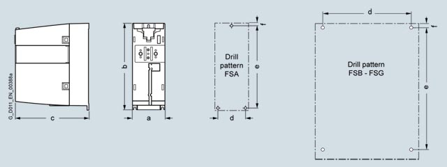
|
Frame size |
Dimensions in mm (inches) |
Drilling dimensions in mm (inches) |
Cooling clearance 2) in mm (inches) |
Mounting |
||||||
|---|---|---|---|---|---|---|---|---|---|---|
|
|
a |
b |
c |
d |
e |
f |
top |
bottom |
front |
With bolts |
|
PM240-2 Power Modules, standard variant, with/without integrated line filter |
||||||||||
|
FSA |
73 |
196 |
165 |
62.3 |
186 |
6 |
80 |
100 |
0 |
3 × M4 |
|
FSB |
100 |
292 |
165 |
80 |
281 |
6 |
80 |
100 |
0 |
4 × M4 |
|
FSC |
140 |
355 |
165 |
120 |
343 |
6 |
80 |
100 |
0 |
4 × M5 |
|
FSD |
200 |
472 |
237 |
170 |
430 |
7 |
300 |
350 |
100 |
4 × M5 |
|
FSE |
275 |
551 |
237 |
230 |
509 |
8.5 |
300 |
350 |
100 |
4 x M6 |
|
FSF |
305 |
708 |
357 |
270 |
680 |
13 |
300 |
350 |
100 |
4 × M8 |
|
FSG |
305 |
1000 |
357 |
265 |
970.5 |
15 |
300 |
350 |
100 |
4 × M10 |
1) Increased depth:
• When the CU230P-2 Control Unit is plugged on, the depth increases by
- 58 mm (2.28 in) for frame sizes FSA to FSC
- 16 mm (0.63 in) for PM240‑2, frame sizes FSD to FSG
• When the CU240E-2 Control Unit is plugged on, the depth increases by
- 41 mm (1.61 in) for frame sizes FSA to FSC
- 0 mm (0 in) for PM240‑2, frame sizes FSD to FSG
• When the CU250S-2 Control Unit is plugged in, the depth increases by
- 62 mm (2.44 in) for frame sizes FSA to FSC
- 19 mm (0.75 in) for PM240‑2, frame sizes FSD to FSG
• When the IOP‑2/BOP‑2 is plugged on, the depth increases by a further 11 mm (0.43 in)
2)The Power Modules can be mounted side by side. A side clearance of 1 mm (0.04 in) is recommended for tolerance-related reasons.
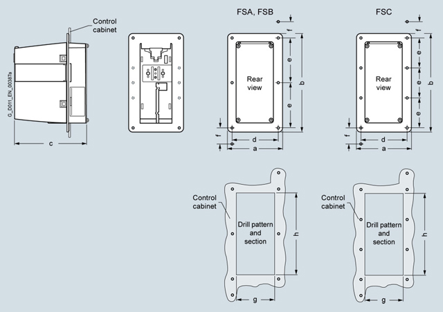
|
Frame size |
Dimensions in mm (inches) |
Drilling dimensions in mm (inches) |
Section of cabinet in mm (inches) |
Cooling clearance in mm (inches) |
Mounting |
|||||||
|---|---|---|---|---|---|---|---|---|---|---|---|---|
|
|
a |
b |
c |
d |
e |
f |
g |
h |
top |
bottom |
side 2) |
With bolts |
|
PM240‑2 Power Modules, IP20 degree of protection, push-through variant, with/without integrated line filter class A |
||||||||||||
|
FSA |
126 |
238 |
171 |
106 |
103 |
27 |
88 |
198 |
80 |
100 |
0 |
8 × M5 |
|
FSB |
154 |
345 |
171 |
134 |
148 |
34.5 |
116 |
304 |
80 |
100 |
0 |
8 × M5 |
|
FSC |
200 |
411 |
171 |
174 |
123 |
30.5 |
156 |
365 |
80 |
100 |
0 |
10 × M5 |
1) Overall depth, of which 117.7 mm (4.63 in) is inside and 53.1 mm (2.09 in) is outside the control cabinet. Increased depth:
• When the CU230P‑2 Control Unit is plugged on, the depth increases by 58 mm (2.28 in)
• When the CU240E-2 Control Unit is plugged on, the depth increases by 41 mm (1.61 in)
• When the CU250S-2 Control Unit is plugged on, the depth increases by 62 mm (2.44 in)
• When the IOP‑2/BOP‑2 is plugged on, the depth increases by a further 11 mm (0.43 in)
2) The Power Modules can be mounted side by side (mounting frame to mounting frame). A side clearance of 1 mm (0.04 in) is recommended for tolerance-related reasons.
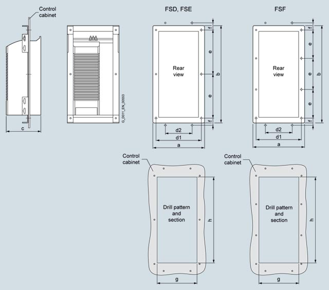
|
Frame size |
Dimensions in mm (inches) |
Drilling dimensions in mm (inches) |
Section of cabinet in mm (inches) |
Cooling clearance in mm (inches) |
Mounting |
|||||||||
|---|---|---|---|---|---|---|---|---|---|---|---|---|---|---|
|
|
a |
b |
c |
d1 |
d2 |
e |
f |
g |
h |
top |
bottom |
side 2) |
front |
With bolts |
|
PM240‑2 Power Modules, IP20 degree of protection, push-through variant, with/without integrated line filter class A |
||||||||||||||
|
FSD |
275 |
517 |
238.5 |
276 |
145 |
240 |
39 |
216 |
468 |
350 |
350 |
0 |
29 |
10 × M5 |
|
FSE |
354 |
615 |
238.5 |
302.5 |
230 |
297.5 |
45 |
285 |
545 |
350 |
350 |
0 |
29 |
10 × M5 |
|
FSF |
384 |
785 |
358 |
350 |
223 |
227 |
48 |
315 |
690 |
80 |
100 |
0 |
100 |
12 × M5 |
1) Overall depth, of which for FSD and FSE 141 mm (5.55 in) is inside and 97.5 mm (3.84 in) outside the control cabinet, and for frame size FSF 177.5 mm (6.99 in) inside and 180.5 mm (7.1 in) outside the control cabinet. Increased depth:
• When the CU230P‑2 Control Unit is plugged on, the depth increases by 15.5 mm (0.61 in), and with blanking cover, IOP‑2 or BOP‑2 by a further 11 mm (0.43 in)
• When the CU240E-2 Control Unit is plugged on, the depth does not increase, and with blanking cover, IOP‑2 or BOP‑2 by 11 mm (0.43 in)
• When the CU250S‑2 Control Unit is plugged on, the depth increases by 18.5 mm (0.73 in), and with blanking cover, IOP‑2 or BOP‑2 by a further 11 mm (0.43 in)
2) The Power Modules can be mounted side by side (mounting frame to mounting frame). A side clearance of 1 mm (0.04 in) is recommended for tolerance-related reasons.
(Nguyễn Thảo Trường - http://DienElectric.com theo Siemens)
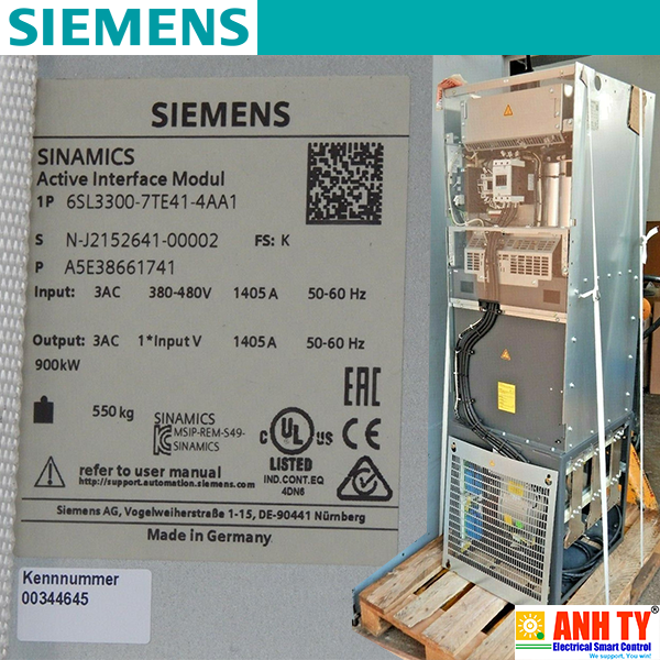 Mô-đun giao dien kích hoạt Siemens 6SL3300-7TE41-4AA1Giá tốt nhất xem...0909186879 Email
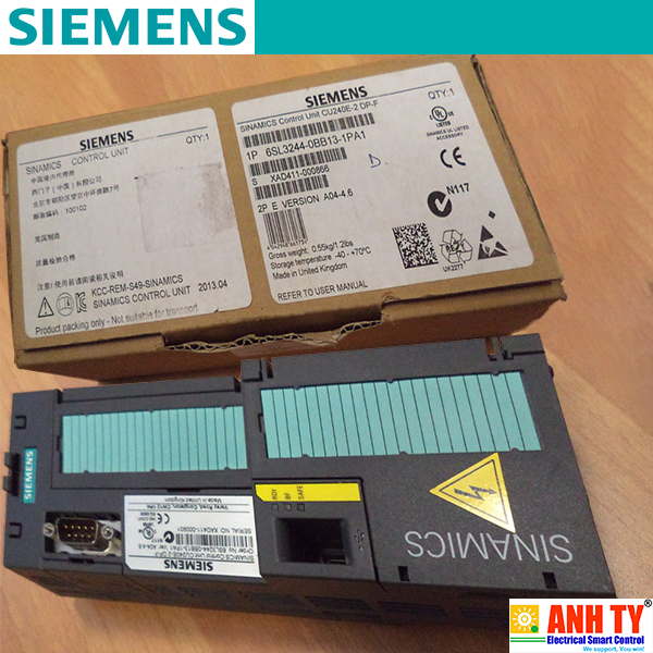 Mô-đun điều khiển CU240E-2 DP-F Siemens 6SL3244-0BB13-1PA1Giá tốt nhất xem...0909186879 Email
 Mô-đun SINUMERIK 840D sl NCU 720.3B PN Siemens 6FC5372-0AA30-0AB0Giá tốt nhất xem...0909186879 Email
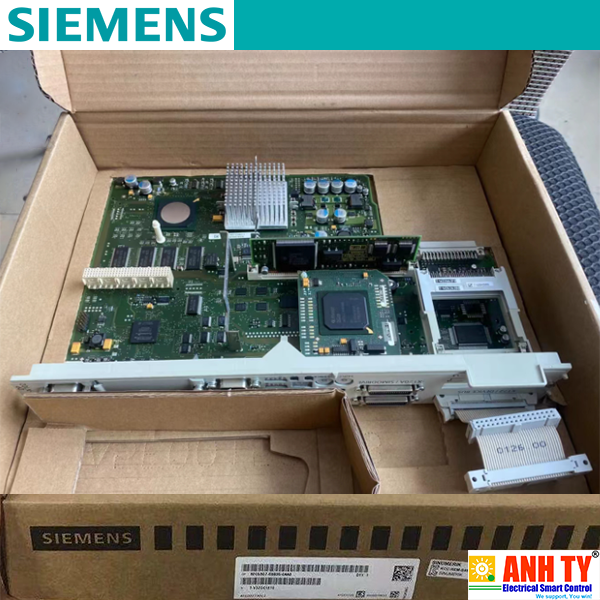 Bo mạch SINUMERIK 840D/DE CNC NCU 573.5 Siemens 6FC5357-0BB35-0AA0Giá tốt nhất xem...0909186879 Email
 Màn hình điều khiển AOP30 V2.4 Siemens 6SL3055-0AA00-4CA5Giá tốt nhất xem...0909186879 Email
 Biến tần Inverter Siemens - SINAMICS G120C 30.0kW 3AC 380-480V 47-63Hz - 6SL3210-1KE26-0AF1Giá tốt nhất Xem...0909186879 Email
 Biến tần Inverter Siemens - SINAMICS G120C 18.5kW 3AC 380-480V 47-63Hz - 6SL3210-1KE23-8AF1Giá tốt nhất Xem...0909186879 Email
 Biến tần Inverter Siemens - SINAMICS G120C 0.75kW 3AC 380-480V 47-63Hz - 6SL3210-1KE12-3AB2Giá tốt nhất Xem...0909186879 EmailBiến tần G120 Module công suất 3AC 400V 7.5kW FSB - Siemens - SINAMICS Power module PM240-2 6SL3210-1PE21-8UL0Giá tốt nhất Xem...0909186879 Email
 Biến tần Inverter Siemens - SINAMICS G120C - 6SL3210-1KE28-4AF1Giá tốt nhất Xem...0909186879 Email
 Biến tần Inverter Siemens - SINAMICS G120C - 6SL3210-1KE27-0AF1Giá tốt nhất Xem...0909186879 Email
 Biến tần Inverter Siemens - SINAMICS G120C 0.75kW 3AC 380-480V 47-63Hz - 6SL3210-1KE12-3AP2Giá tốt nhất Xem...0909186879 Email
 Biến tần Inverter Siemens - SINAMICS G120C 1.5kW 3AC 380-480V 47-63Hz - 6SL3210-1KE14-3AF2Giá tốt nhất Xem...0909186879 Email
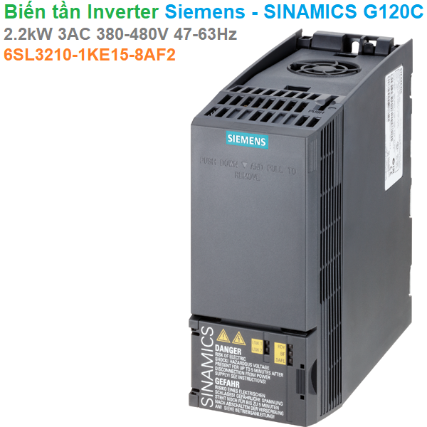 Biến tần Inverter Siemens - SINAMICS G120C 2.2kW 3AC 380-480V 47-63Hz - 6SL3210-1KE15-8AF2Giá tốt nhất Xem...0909186879 Email
 Hãy xem tầm qua trong của RCCB và ELCB trong việc cứu nạn nhân bị điện giựt thoát chết như thế nào..
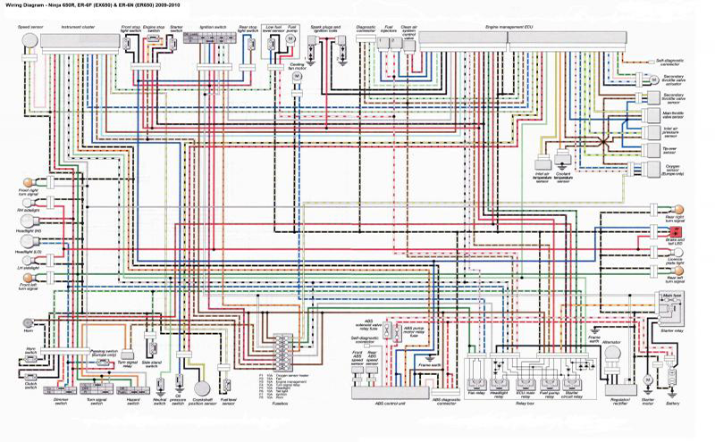 Lắp điện là lắp đặt, đấu nối hệ thống dây, cáp điện động lực, điều khiển, truyền thông và chác thiết bị liên quan như thiết bị chuyển mạch (CB), tủ điện

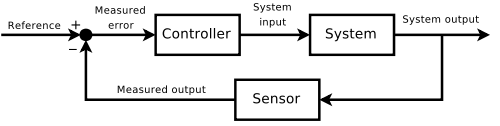 Lý thuyết điều khiển tự động là một nhánh liên ngành của kỹ thuật và toán học, liên quan đến hành vi của
 Điều khiển quá trình (PLC) được sử dụng rộng rãi trong công nghiệp và cho phép sản xuất hàng loạt các sản phẩm phù hợp với các
 Trong một báo cáo mới, dự đoán năm 2018: IoT chuyển từ thử nghiệm sang kinh doanh quy mô, Forrester Research dự đoán rằng IoT sẽ trở thành xương sống của
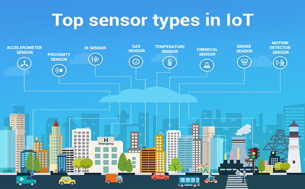 Nền tảng IoT hoạt động và cung cấp các dạng thông minh và dữ liệu có giá trị với việc sử dụng nhiều cảm biến khác nhau. Chúng phục vụ để thu
 Hydrogen là một nguyên tố chiếm tỷ lệ cao nhất so với tất cả các nguyên tố khác trên địa cầu. Nhưng hydrogen không hiện diện dưới dạng nguyên tử hay
 Năng lượng tái tạo như điện gió và điện mặt trời có một nhược điểm căn bản, đó là không ổn định. Chúng chỉ vận hành khi có
 BBC Future - Hành tinh của chúng ta gặp một vấn đề. Con người, như tất cả các sinh vật sống khác, thải ra rất nhiều những chất thải không dễ chịu
 Khi robot sinh học này phát hiện ra khối u, bốn cánh tay trên cấu trúc vi mô tự động uốn cong, giải phóng tế bào tinh trùng, xâm