dienelectrics@gmail.com
 0909186879 dienelectrics@gmail.com
Note:
SIMATIC Memory Card required for operation of the CPU
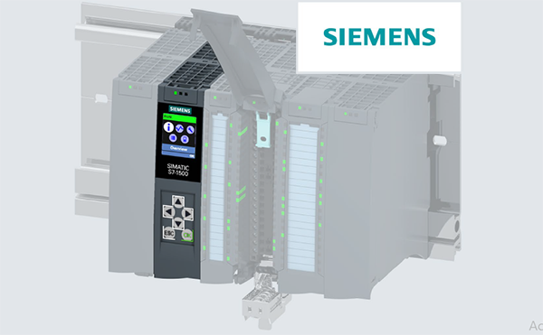
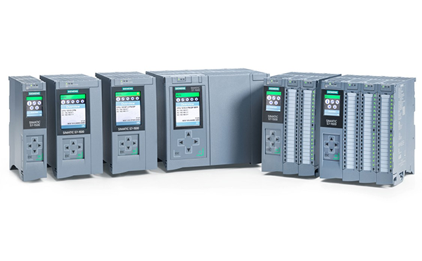
The CPU 1511-1 PN is the cost-effective entry-level CPU for applications with medium requirements for processing speed and speed of response in discrete production technology. The CPU 1511-1 PN can be used as a PROFINET IO controller or as distributed intelligence (PROFINET I-Device). The integrated PROFINET IO IRT interface is designed as 2-port switch so that a linear topology can be set up in the system. In addition, the CPU offers comprehensive control functionalities via easy-to-configure blocks as well as the ability to connect drives via standardized PLC-open blocks.
The CPU 1511-1 PN features:
- A powerful processor:|
Article number |
6ES7511-1AK02-0AB0 |
|
|
|
CPU 1511-1PN, 150KB Program, 1MB Data |
|
|
General information |
|
|
|
Product type designation |
CPU 1511-1 PN |
|
|
HW functional status |
FS01 |
|
|
Firmware version |
V2.6 |
|
|
Product function |
|
|
|
Yes; I&M0 to I&M3 |
|
|
Engineering with |
|
|
|
V15.1 (FW V2.6) / V15 (FW V2.5) or higher; with older TIA Portal versions configurable as 6ES7511-1AK01-0AB0 |
|
|
Configuration control |
|
|
|
via dataset |
Yes |
|
|
Display |
|
|
|
Screen diagonal [cm] |
3.45 cm |
|
|
Control elements |
|
|
|
Number of keys |
8 |
|
|
Mode buttons |
2 |
|
|
Supply voltage |
|
|
|
Type of supply voltage |
24 V DC |
|
|
permissible range, lower limit (DC) |
19.2 V |
|
|
permissible range, upper limit (DC) |
28.8 V |
|
|
Reverse polarity protection |
Yes |
|
|
Mains buffering |
|
|
|
5 ms |
|
|
1/s |
|
|
Input current |
|
|
|
Current consumption (rated value) |
0.7 A |
|
|
Current consumption, max. |
0.95 A |
|
|
Inrush current, max. |
1.9 A; Rated value |
|
|
I²t |
0.02 A²·s |
|
|
Power |
|
|
|
Infeed power to the backplane bus |
10 W |
|
|
Power consumption from the backplane bus (balanced) |
5.5 W |
|
|
Power loss |
|
|
|
Power loss, typ. |
5.7 W |
|
|
Memory |
|
|
|
Number of slots for SIMATIC memory card |
1 |
|
|
SIMATIC memory card required |
Yes |
|
|
Work memory |
|
|
|
150 kbyte |
|
|
1 Mbyte |
|
|
Load memory |
|
|
|
32 Gbyte |
|
|
Backup |
|
|
|
Yes |
|
|
CPU processing times |
|
|
|
for bit operations, typ. |
60 ns |
|
|
for word operations, typ. |
72 ns |
|
|
for fixed point arithmetic, typ. |
96 ns |
|
|
for floating point arithmetic, typ. |
384 ns |
|
|
CPU-blocks |
|
|
|
Number of elements (total) |
2 000; Blocks (OB, FB, FC, DB) and UDTs |
|
|
DB |
|
|
|
1 ... 60 999; subdivided into: number range that can be used by the user: 1 ... 59 999, and number range of DBs created via SFC 86: 60 000 ... 60 999 |
|
|
1 Mbyte; For DBs with absolute addressing, the max. size is 64 KB |
|
|
FB |
|
|
|
0 ... 65 535 |
|
|
150 kbyte |
|
|
FC |
|
|
|
0 ... 65 535 |
|
|
150 kbyte |
|
|
OB |
|
|
|
150 kbyte |
|
|
100 |
|
|
20 |
|
|
20 |
|
|
20; With minimum OB 3x cycle of 500 µs |
|
|
50 |
|
|
3 |
|
|
2 |
|
|
2 |
|
|
100 |
|
|
4 |
|
|
2 |
|
|
1 |
|
|
Nesting depth |
|
|
|
24 |
|
|
Counters, timers and their retentivity |
|
|
|
S7 counter |
|
|
|
2 048 |
|
|
Retentivity |
|
|
|
Yes |
|
|
IEC counter |
|
|
|
Any (only limited by the main memory) |
|
|
Retentivity |
|
|
|
Yes |
|
|
S7 times |
|
|
|
2 048 |
|
|
Retentivity |
|
|
|
Yes |
|
|
IEC timer |
|
|
|
Any (only limited by the main memory) |
|
|
Retentivity |
|
|
|
Yes |
|
|
Data areas and their retentivity |
|
|
|
Retentive data area (incl. timers, counters, flags), max. |
128 kbyte; In total; available retentive memory for bit memories, timers, counters, DBs, and technology data (axes): 88 KB |
|
|
Extended retentive data area (incl. timers, counters, flags), max. |
1 Mbyte; When using PS 6 0W 24/48/60 V DC HF |
|
|
Flag |
|
|
|
16 kbyte |
|
|
8; 8 clock memory bit, grouped into one clock memory byte |
|
|
Data blocks |
|
|
|
No |
|
|
Local data |
|
|
|
64 kbyte; max. 16 KB per block |
|
|
Address area |
|
|
|
Number of IO modules |
1 024; max. number of modules / submodules |
|
|
I/O address area |
|
|
|
32 kbyte; All inputs are in the process image |
|
|
32 kbyte; All outputs are in the process image |
|
|
per integrated IO subsystem |
|
|
|
8 kbyte |
|
|
8 kbyte |
|
|
per CM/CP |
|
|
|
8 kbyte |
|
|
8 kbyte |
|
|
Subprocess images |
|
|
|
32 |
|
|
Hardware configuration |
|
|
|
Number of distributed IO systems |
32; A distributed I/O system is characterized not only by the integration of distributed I/O via PROFINET or PROFIBUS communication modules, but also by the connection of I/O via AS-i master modules or links (e.g. IE/PB-Link) |
|
|
Number of DP masters |
|
|
|
4; A maximum of 4 CMs/CPs (PROFIBUS, PROFINET, Ethernet) can be inserted in total |
|
|
Number of IO Controllers |
|
|
|
1 |
|
|
4; A maximum of 4 CMs/CPs (PROFIBUS, PROFINET, Ethernet) can be inserted in total |
|
|
Rack |
|
|
|
32; CPU + 31 modules |
|
|
1 |
|
|
PtP CM |
|
|
|
the number of connectable PtP CMs is only limited by the number of available slots |
|
|
Time of day |
|
|
|
Clock |
|
|
|
Hardware clock |
|
|
6 wk; At 40 °C ambient temperature, typically |
|
|
10 s; Typ.: 2 s |
|
|
Operating hours counter |
|
|
|
16 |
|
|
Clock synchronization |
|
|
|
Yes |
|
|
Yes |
|
|
Yes |
|
|
Yes |
|
|
Interfaces |
|
|
|
Number of PROFINET interfaces |
1 |
|
|
1. Interface |
|
|
|
Interface types |
|
|
|
2 |
|
|
Yes |
|
|
Yes; X1 |
|
|
Protocols |
|
|
|
Yes; IPv4 |
|
|
Yes |
|
|
Yes |
|
|
Yes |
|
|
Yes |
|
|
Yes |
|
|
Yes; MRP Automanager according to IEC 62439-2 Edition 2.0 |
|
|
PROFINET IO Controller |
|
|
|
Services |
|
|
|
Yes |
|
|
Yes |
|
|
Yes |
|
|
Yes |
|
|
Yes |
|
|
Yes; As MRP redundancy manager and/or MRP client; max. number of devices in the ring: 50 |
|
|
Yes; Requirement: IRT |
|
|
Yes |
|
|
Yes; Max. 32 PROFINET devices |
|
|
128; In total, up to 256 distributed I/O devices can be connected via AS-i, PROFIBUS or PROFINET |
|
|
64 |
|
|
128 |
|
|
128 |
|
|
8; in total across all interfaces |
|
|
8 |
|
|
The minimum value of the update time also depends on communication share set for PROFINET IO, on the number of IO devices, and on the quantity of configured user data |
|
|
Update time for IRT |
|
|
|
250 μs to 4 ms; Note: In the case of IRT with isochronous mode, the minimum update time of 625 µs of the isochronous OB is decisive |
|
|
500 μs to 8 ms; Note: In the case of IRT with isochronous mode, the minimum update time of 625 µs of the isochronous OB is decisive |
|
|
1 ms to 16 ms |
|
|
2 ms to 32 ms |
|
|
4 ms to 64 ms |
|
|
Update time = set "odd" send clock (any multiple of 125 µs: 375 µs, 625 µs ... 3 875 µs) |
|
|
Update time for RT |
|
|
|
250 µs to 128 ms |
|
|
500 µs to 256 ms |
|
|
1 ms to 512 ms |
|
|
2 ms to 512 ms |
|
|
4 ms to 512 ms |
|
|
PROFINET IO Device |
|
|
|
Services |
|
|
|
Yes |
|
|
Yes |
|
|
No |
|
|
Yes |
|
|
Yes |
|
|
Yes; As MRP redundancy manager and/or MRP client; max. number of devices in the ring: 50 |
|
|
Yes; Requirement: IRT |
|
|
Yes |
|
|
Yes |
|
|
4 |
|
|
Yes; Per user program |
|
|
Interface types |
|
|
|
RJ 45 (Ethernet) |
|
|
|
Yes |
|
|
Yes |
|
|
Yes |
|
|
Yes |
|
|
Protocols |
|
|
|
Number of connections |
|
|
|
96; via integrated interfaces of the CPU and connected CPs / CMs |
|
|
10 |
|
|
64 |
|
|
16 |
|
|
Redundancy mode |
|
|
|
Yes |
|
|
SIMATIC communication |
|
|
|
Yes |
|
|
Yes |
|
|
See online help (S7 communication, user data size) |
|
|
Open IE communication |
|
|
|
Yes |
|
|
64 kbyte |
|
|
Yes |
|
|
Yes |
|
|
64 kbyte |
|
|
Yes |
|
|
2 kbyte; 1 472 bytes for UDP broadcast |
|
|
Yes; Max. 5 multicast circuits |
|
|
No |
|
|
Yes |
|
|
Yes |
|
|
Yes |
|
|
Web server |
|
|
|
Yes; Standard and user pages |
|
|
Yes; Standard and user pages |
|
|
OPC UA |
|
|
|
Yes |
|
|
Yes |
|
|
Yes |
|
|
Available security policies: None, Basic128Rsa15, Basic256Rsa15, Basic256Sha256 |
|
|
"anonymous" or by user name & password |
|
|
4 |
|
|
1 000 |
|
|
300 |
|
|
20 |
|
|
100 |
|
|
1 |
|
|
5 |
|
|
5 000 |
|
|
100 |
|
|
20 |
|
|
Yes; Data access (read, write, subscribe), method call, custom address space |
|
|
Yes |
|
|
Available security policies: None, Basic128Rsa15, Basic256Rsa15, Basic256Sha256 |
|
|
"anonymous" or by user name & password |
|
|
32 |
|
|
50 000 |
|
|
10 000 |
|
|
20 |
|
|
100 ms |
|
|
500 ms |
|
|
20 |
|
|
20 |
|
|
1 000; For 1 s sampling interval and 1 s send interval |
|
|
10 |
|
|
1 000 |
|
|
Further protocols |
|
|
|
Yes; MODBUS TCP |
|
|
Media redundancy |
|
|
|
200 ms; For MRP, bumpless for MRPD |
|
|
50 |
|
|
Isochronous mode |
|
|
|
Isochronous operation (application synchronized up to terminal) |
Yes; Distributed and central; with minimum OB 6x cycle of 625 µs (distributed) and 1 ms (central) |
|
|
Equidistance |
Yes |
|
|
S7 message functions |
|
|
|
Number of login stations for message functions, max. |
32 |
|
|
Program alarms |
Yes |
|
|
Number of configurable program messages, max. |
5 000; Program messages are generated by the "Program_Alarm" block, ProDiag or GRAPH |
|
|
Number of loadable program messages in RUN, max. |
2 500 |
|
|
Number of simultaneously active program alarms |
|
|
|
300 |
|
|
100 |
|
|
80 |
|
|
Test commissioning functions |
|
|
|
Joint commission (Team Engineering) |
Yes; Parallel online access possible for up to 5 engineering systems |
|
|
Status block |
Yes; Up to 8 simultaneously (in total across all ES clients) |
|
|
Single step |
No |
|
|
Number of breakpoints |
8 |
|
|
Status/control |
|
|
|
Yes |
|
|
Inputs/outputs, memory bits, DBs, distributed I/Os, timers, counters |
|
|
|
|
|
200; per job |
|
|
200; per job |
|
|
Forcing |
|
|
|
Peripheral inputs/outputs |
|
|
200 |
|
|
Diagnostic buffer |
|
|
|
Yes |
|
|
1 000 |
|
|
500 |
|
|
Traces |
|
|
|
4; Up to 512 KB of data per trace are possible |
|
|
Interrupts/diagnostics/status information |
|
|
|
Diagnostics indication LED |
|
|
|
Yes |
|
|
Yes |
|
|
Yes |
|
|
Yes |
|
|
Yes |
|
|
Supported technology objects |
|
|
|
Motion Control |
Yes; Note: The number of axes affects the cycle time of the PLC program; selection guide via the TIA Selection Tool or SIZER |
|
|
800 |
|
|
|
|
|
40 |
|
|
80 |
|
|
160 |
|
|
80 |
|
|
20 |
|
|
160 |
|
|
40 |
|
|
|
|
|
5 |
|
|
10 |
|
|
Controller |
|
|
|
Yes; Universal PID controller with integrated optimization |
|
|
Yes; PID controller with integrated optimization for valves |
|
|
Yes; PID controller with integrated optimization for temperature |
|
|
Counting and measuring |
|
|
|
Yes |
|
|
Ambient conditions |
|
|
|
Ambient temperature during operation |
|
|
|
0 °C |
|
|
60 °C; Display: 50 °C, at an operating temperature of typically 50 °C, the display is switched off |
|
|
0 °C |
|
|
40 °C; Display: 40 °C, at an operating temperature of typically 40 °C, the display is switched off |
|
|
Ambient temperature during storage/transportation |
|
|
|
-40 °C |
|
|
70 °C |
|
|
Configuration |
|
|
|
Programming |
|
|
|
Programming language |
|
|
|
Yes |
|
|
Yes |
|
|
Yes |
|
|
Yes |
|
|
Yes |
|
|
Know-how protection |
|
|
|
Yes |
|
|
Yes |
|
|
Yes |
|
|
Access protection |
|
|
|
Yes |
|
|
Yes |
|
|
Yes |
|
|
Yes |
|
|
Cycle time monitoring |
|
|
|
adjustable minimum cycle time |
|
|
adjustable maximum cycle time |
|
|
Dimensions |
|
|
|
Width |
35 mm |
|
|
Height |
147 mm |
|
|
Depth |
129 mm |
|
|
Weights |
|
|
|
Weight, approx. |
405 g |
|