Biến tần | Inverters

Thông tin chi tiết nhất về Biến tần SINAMICS G120C compact inverters của SIEMENS

SINAMICS G120C đặc biệt nhỏ gọn với mật độ công suất cao và cung cấp một sự kết hợp cân bằng giữa các chức năng để giải quyết một loạt các ứng dụng. Với bảy kích thước khung, nó bao gồm một phạm vi hoạt động của 0,55 kW đến 132 kW.
Thông tin chi tiết nhất về Biến tần SINAMICS G120C compact inverters của SIEMENS
SINAMICS G120C Framesize FSAA, FSA, FSB, FSC, FSD, FSE and FSF with IOP
 
SINAMICS G120C compact inverters cung cấp một sự kết hợp cân bằng giữa các tính năng để giải quyết một loạt các ứng dụng. Chúng là những thiết bị nhỏ gọn, chắc chắn dễ vận hành và có thể được tùy chọn với bảng điều khiển cơ bản hoặc tiên tiến. Chúng đặc biệt phù hợp khi đáp ứng yêu cầu của các nhà tích hợp hệ thống, các nhà sản xuất OEM và các nhà phân phối về năng suất cao và hiệu suất phù hợp.


Kích thước khung mới cho nhiều khả năng lựa chọn

Ba kích thước khung mới FSD (22 kW đến 45 kW), FSE (55 kW) và FSF (75 kW đến 132 kW) thực sự là điểm nổi bật. Vì vậy, các thiết bị nhỏ gọn bây giờ cũng có sẵn cho các phạm vi hiệu suất cao lên đến 132 kW để hoạt động trong lưới điện ba pha. (đã sẵn sàng trong nửa đầu năm 2017)


Kích thước nhỏ gọn, tiết kiệm không gian khi lắp đặt

- Nhỏ gọn ngay cả ở công suất cao lên đến 132 kW
- Tích hợp DC-line reactor và bộ lọc EMC
- Có thể lắp đặt gần nhau tất cả các dạng kích thước khung khác nhau mà không có sự giảm dòng hoặc hiệu suất làm việc
- Khai thác và vận hành đơn giản
- Intuitive series commissioning, chức năng nhân bản thông qua BOP-2, IOP hoặc thẻ SD
- Tham số hóa phần mềm đơn giản và nhanh chóng


Tích hợp hoàn hảo

- Full integration of the drives in the TIA Portal system diagnostics
- The use of the TIA Portal library concept ensures the easy reusability of the converters, including the parameter and hardware components


Công nghệ hàng đầu

- Hiệu quả về năng lượng, điều khiển vector không cảm biến cho phép mô men xoắn cao với các điểm đặt tần số thấp;
- Không yêu cầu thêm các thành phần bên ngoài do chức năng an toàn được chứng nhận Safe Torque Off được tích hợp theo tiêu chuẩn.


Tin cậy trong giao tiếp tương tác

Được hổ trợ tất cả các hệ thống bus thường sử dụng như PROFINET, EtherNet / IP, PROFIBUS và USS / Modbus RTU


Với nhiều chức năng sáng tạo - tất cả các sự kiện quan trọng chỉ trong một nháy mắt

- Điện áp 3AC 380 ... 480 V +10% / -20%
- Dải công suất từ 0,55 đến 132 kW
- Mức độ bảo vệ IP20
- Lớp môi trường Class 3C2, (3C3 với SIPLUS)
- Nhiệt độ môi trường-10 ° đến 40 ° C mà không làm giảm giá trị / đến 60 ° C với việc giảm giá trị
- EMCA theo IEC 61800-3 cho đến loại C2
- StandardsCE, UL, cUL, c-Tick
- Công nghệ an toànTín hiệu tích hợp: Kéo an toàn tắt (STO); được kiểm soát qua thiết bị đầu cuối hoặc PROFIsafe
- Truyền thôngPROFINET, Ethernet / IP, PROFIBUS, USS / Modbus RTU
- Quy trình kiểm soát U / f (tuyến tính, luật vuông, FCC, ECO), điều khiển vector không mã hóa (SLVC)
- Chức năngTốc độ cố định, bộ điều khiển PID, điều khiển phanh động cơ


Ưu điểm

- Thiết kế nhỏ gọn;
- Thiết kế side-by-side
- Mật độ năng lượng cao, kích thước vỏ hẹp;
- Có thể lắp đặt đơn giản trong không gian nhỏ hẹp nhất
- Yêu cầu không gian nhỏ hẹp;
- Sử dụng trong tủ điều khiển nhỏ, gần máy;
- Bộ tham số tối ưu;
- Tối ưu hoá vận hành;
- Tài liệu khởi động
- Có các bảng điều khiển BOP-2 hoặc IOP để sử dụng;
- Kết nối USB tích hợp;
- Tham số phân công được lập trình hoạt độngđơn giản và nhanh;
- Đơn giản sử dụng trong quá trình vận hành và hoạt động;
- Giảm chi phí đào tạo, bí quyết SINAMICS hiện có có thể được sử dụng;
- Mức độ thân thiện với dịch vụ, bảo trì đơn giản;
- Cổng kết nối;
- Chức năng nhân bản sử dụng BOP-2, IOP hoặc thẻ nhớ;
- Bộ đếm thời gian hoạt động cho "drive on" và "motor on";
- Các bộ phận cơ khí lắp ráp nhanh;
- Cơ chế vận hành tiêu chuẩn trực quan;
- Các thành phần được tích hợp hoàn toàn tự động;
- Kiểm soát vector không cảm biến hiệu quả năng lượng cao;
- Tự động giảm dòng với V / f ECO
- Tích hợp với máy tính tiết kiệm năng lượng;
- Tích hợp (STO) có tính an toàn;
- Các phiên bản truyền thông với PROFINET / EtherNet / IP, PROFIBUS DP, USS / Modbus RTU;
- Mô-đun được phủ sơn bảo vệ;
- Hoạt động ở nhiệt độ môi trường xung quanh 60 ° C (140 ° F);


Ứng dụng

Use

Requirements for torque accuracy / speed accuracy / position accuracy / coordination of axes / functionality


Continuous motion

Non-continuous motion


Basic

Medium

High

Basic

Medium

High


Pumping, ventilating, compressing

Centrifugal pumps
Radial / axial fans
Compressors

Centrifugal pumps
Radial / axial fans
Compressors

Eccentric screw pumps

Hydraulic pumps
Metering pumps

Hydraulic pumps
Metering pumps

Descaling pumps
Hydraulic pumps


V20
G120C
G120P

G120P
G130/G150
G180 1)

S120

G120

S110

S120

Moving

Conveyor belts
Roller conveyors
Chain conveyors

Conveyor belts
Roller conveyors
Chain conveyors
Lifting/lowering devices
Elevators
Escalators/moving walkways
Indoor cranes
Marine drives
Cable railways

Elevators
Container cranes
Mining hoists
Excavators for open-cast mining
Test bays

Acceleration conveyors
Storage and retrieval machines

Acceleration conveyors
Storage and retrieval machines
Cross cutters
Reel changers

Storage and retrieval machines
Robotics
Pick & place
Rotary indexing tables
Cross cutters
Roll feeds
Engagers/disengagers


V20
G110D
G110M
G120C
ET 200pro FC‑2 2)

G120
G120D
G130/G150
G180 1)

S120
S150
DCM

V90
G120
G120D

S110
DCM

S120
DCM

Processing

Mills
Mixers
Kneaders
Crushers
Agitators
Centrifuges

Mills
Mixers
Kneaders
Crushers
Agitators
Centrifuges
Extruders
Rotary furnaces

Extruders
Winders/unwinders
Lead/follower drives
Calenders
Main press drives
Printing machines

Tubular bagging machines
Single-axis motion control
such as 
• Position profiles
• Path profiles

Tubular bagging machines
Single-axis motion control
such as 
• Position profiles
• Path profiles

Servo presses
Rolling mill drives
Multi-axis motion control
such as
• Multi-axis positioning
• Cams
• Interpolations


V20
G120C

G120
G130/G150
G180 1)

S120
S150
DCM

V90
G120

S110

S120
DCM

Machining

Main drives for
• Turning
• Milling
• Drilling

Main drives for
• Drilling
• Sawing

Main drives for
• Turning
• Milling
• Drilling
• Gear cutting
• Grinding

Axis drives for
• Turning
• Milling
• Drilling

Axis drives for
• Drilling
• Sawing

Axis drives for
• Turning
• Milling
• Drilling
• Lasering
• Gear cutting
• Grinding
• Nibbling and punching


S110

S110
S120

S120

S110

S110
S120

S120

1) Industry-specific drives.

2) Information on the SIMATIC ET 200pro FC‑2 frequency converter is available at http://www.siemens.com/et200pro-fc


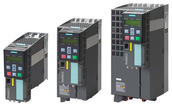
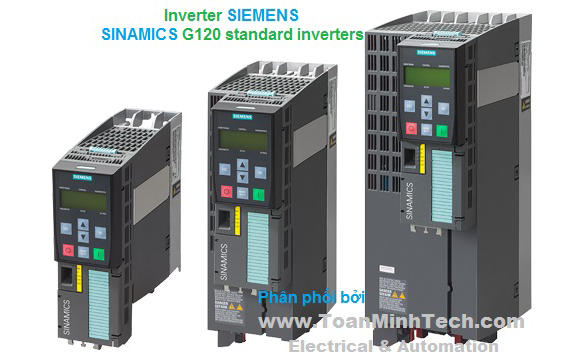
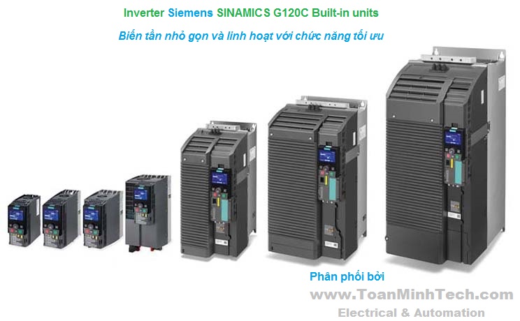
Bộ biến tần SINAMICS G120C nhỏ gọn liên tục kiểm soát tốc độ động cơ không đồng bộ ba pha (cảm ứng) và có thể được sử dụng trong nhiều lĩnh vực công nghiệp. Chúng thường thích hợp cho các ứng dụng liên quan đến băng tải, máy trộn, máy đùn, máy bơm, quạt, máy nén và máy xử lý cơ bản.


Các ví dụ và mô tả ứng dụng thực tiễn có sẵn tại: http://www.siemens.com/sinamics-applications


Thiết kế

SINAMICS G120C là một bộ chuyển đổi nhỏ gọn cho tủ điều khiển gắn ở mức độ bảo vệ IP20, nơi các đơn vị chức năng điều khiển (CU) và Module Nguồn (PM) được kết hợp trong một thiết bị.
 
Thiết kế cơ khí nhỏ gọn và mật độ công suất cao cho phép các thiết bị này được lắp đặt trong các tủ điều khiển của máy điều khiển và cabinnet điều khiển để tối đa sử dụng không gian. Bộ chuyển đổi nhỏ gọn SINAMICS G120C có thể được gắn trực tiếp vào butt-mounted mà không làm giảm giá trị ở nhiệt độ lên tới 40 ° C (104 ° F).
 
SINAMICS G120C, frame size FSAA with BOP-2
 
SINAMICS G120C có thể được tích hợp vào các ứng dụng rộng nhất, sử dụng đầu vào kỹ thuật số và analog tích hợp hoặc thông qua giao diện fieldbus tích hợp (có sẵn trong các phiên bản USS, Modbus RTU, PROFIBUS, PROFINET / EtherNet / IP). Đặc biệt các phiên bản sản phẩm với giao diện PROFIBUS / PROFINET đã tích hợp có thể cho phép tích hợp hoàn toàn vào gia đình Siemens TIA, do đó cho phép tận dụng tối đa lợi thế của dòng sản phẩm TIA liền mạch. Các thiết bị SINAMICS G120C được cài sẵn trong nhà máy để chúng có thể kết nối ngay với các hệ thống PROFIBUS và / hoặc PROFIBUS fieldbus mà không cần tham số hóa.
 
SINAMICS G120C cũng được trang bị với chức năng an toàn STO (Safe Torque Off) theo tiêu chuẩn, được sử dụng để dừng drive điều khiển một cách an toàn. Nhờ đó, các nhà sản xuất máy móc có thể đơn giản có thể vận hành máy móc hiện hành với chi phí liên quan tối thiểu.
 
SINAMICS G120C có thể điều khiển động cơ không đồng bộ (cảm ứng) trong khoảng công suất từ ​​0.37 kW đến 132 kW (0.5 hp đến 200 hp). Vận hành động cơ đáng tin cậy và hiệu quả đạt được bằng cách sử dụng công nghệ IGBT tiên tiến kết hợp với điều khiển vector. Một loạt các chức năng tích hợp trong SINAMICS G120C cũng mang lại mức độ bảo vệ cao cho bộ chuyển đổi và động cơ.
 
Line-side components


Line reactors
Line reactors smooth the current drawn by the converter and thus reduce harmonic components in the line current. Through the reduction of the current harmonics, the thermal load on the power components in the rectifier and in the DC-link capacitors is reduced as well as the harmonic effects on the supply. The use of a line reactor increases the service life of the converter.


Recommended line-side power components
Standard fuses can be used for the SINAMICS G120C. These must be dimensioned to comply with local regulations. In this chapter, you will find recommended components such as fuses and circuit breakers in compliance with IEC and UL regulations.


DC link components
Braking resistors
Excess energy in the DC link is dissipated in the braking resistor. The braking resistors are designed for use with the SINAMICS G120C. This has an integrated braking chopper (electronic switch).


Load-side power components
Output reactors
Output reactors reduce the rate of voltage rise (dv/dt) and the height of the current peaks, and enable longer motor cables to be connected.


Supplementary system components
Intelligent Operator Panel IOP
Graphics-based, user-friendly and powerful operator panel for commissioning and diagnostics as well as local operator control and monitoring of SINAMICS G120C.


Basic Operator Panel BOP-2
A 2-line display to provide support when commissioning and troubleshooting the drive. The drive can be locally controlled.


Memory card
The parameter settings for an inverter can be stored on the SINAMICS SD memory card. When service is required, e.g. after the inverter has been replaced and the data have been downloaded from the memory card the drive system is immediately ready for use again. The associated memory card holder is integrated in the inverter.


PC inverter connection kit 2
For controlling and commissioning an inverter directly from a PC if the STARTER commissioning tool or SINAMICS Startdrive has been installed on the PC.


Spare parts
Shield plates
A set of shield plates is included in the scope of delivery for the motor and signal cables corresponding to the frame size of the SINAMICS G120C, and can also be ordered as spare parts.


Spare parts kit
This kit comprises four I/O terminals, one RS485 terminal, two pairs of Control Unit doors (1 × PN and 1 × other communication versions) and one blanking cover.


Set of connectors
A set of connectors for the line feeder cable, braking resistor and motor cable can be ordered corresponding to the frame size of the SINAMICS G120C inverter.


Roof-mounted fan
A roof-mounted fan (at the top of the device) comprising a pre-assembled unit with holder and fan can be ordered corresponding to the frame size of the SINAMICS G120C.


Fan unit
A replacement fan (at the rear of the device; heat sink) comprising a pre-assembled unit with holder and fan can be ordered corresponding to the frame size of the SINAMICS G120C.


Tích hợp

Connection example for SINAMICS G120C
 
USS/Modbus RTU communication interface
 
PROFIBUS DP communication interface
 
PROFINET, EtherNet/IP communication interface
 

Cấu hình

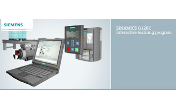
The following electronic configuring aids and engineering tools are available for SINAMICS G120C compact inverters:
 

Drive Technology Configurator (DT Configurator) within the CA 01

The interactive catalog CA 01 – the offline Industry Mall of Siemens on DVD‑ROM – contains over 100 000 products with approximately 5 million possible drive system product variants. The Drive Technology Configurator (DT Configurator) has been developed to facilitate selection of the correct motor and/or inverter from the wide spectrum of drives. It is integrated in Catalog CA 01 as an add-on on DVD‑ROM.


Online DT Configurator

In addition, the DT Configurator can be used on the Internet without requiring any installation. The DT Configurator can be found in the Siemens Industry Mall at the following address: 

http://www.siemens.com/dt-configurator


SIZER for Siemens Drives engineering tool

The SIZER for Siemens Drives engineering tool makes it easy to engineer the SINAMICS drive family. It provides support when selecting the hardware and firmware components necessary to implement a drive task. SIZER for Siemens Drives is designed to support configuring of the entire drive system.


You can find further information on the SIZER for Siemens Drives engineering tool in the chapter Engineering tools.

The SIZER for Siemens Drives engineering tool is available free on the Internet at 
http://www.siemens.com/sizer


STARTER commissioning tool

The STARTER commissioning tool allows menu-prompted commissioning, optimization and diagnostics. Apart from the SINAMICS drives, STARTER is also suitable for MICROMASTER 4 devices.
 

You can find further information about the STARTER commissioning tool in the chapter Engineering tools.

Additional information about the STARTER commissioning tool is available on the Internet at 
http://www.siemens.com/starter


SINAMICS Startdrive commissioning tool

SINAMICS Startdrive is a tool for configuring, commissioning, and diagnosing the SINAMICS family of drives and is integrated into the TIA Portal. SINAMICS Startdrive can be used to implement drive tasks with the SINAMICS G110M, SINAMICS G120, SINAMICS G120C, SINAMICS G120D and SINAMICS G120P inverter series. The commissioning tool has been optimized with regard to user friendliness and consistent use of the TIA Portal benefits of a common working environment for PLC, HMI and drives.
 

You can find further information on the SINAMICS Startdrive commissioning tool in the chapter Engineering tools.
The SINAMICS Startdrive commissioning tool is available free on the Internet at 
http://www.siemens.com/startdrive


Drive ES engineering system

Drive ES is the engineering system that can be used to integrate the communication, configuration and data management functions of Siemens drive technology into the SIMATIC automation world easily, efficiently and cost-effectively. Two software packages are available for SINAMICS – Drive ES Basic and Drive ES PCS.

You can find further information about the Drive ES engineering system in the chapter Engineering tools.

Additional information about the Drive ES engineering system is available on the Internet at 
http://www.siemens.com/drive-es


Thông số kỹ thuật

Unless explicitly specified otherwise, the following technical specifications are valid for all SINAMICS G120C compact converters.

General technical specifications

Mechanical specifications

Vibratory load


  • Transport acc. to EN 60721‑3‑2 1)

Class 1M2

  • Operation acc. to EN 60721‑3‑3

Class 3M1

Shock load


  • Transport acc. to EN 60721‑3‑2 1)

Class 1M2

  • Operation acc. to EN 60721‑3‑3

Class 3M2

Degree of protection

IP20/ UL open type

Permissible mounting position

Vertical wall mounting

Ambient conditions

Protection class

According to EN 61800‑5‑1

Class III (PELV1)

Touch protection

According to EN 61800‑5‑1

Class I (with protective conductor system)

Humidity, max.

95 % at 40 °C (104 °F), condensation and icing not permissible

Ambient temperature


  • Storage 1) acc. to EN 60068‑2‑1

-40 ... +70 °C (-40 ... +158 °F)

  • Transport 1) acc. to EN 60068‑2‑1

-40 ... +70 °C (-40 ... +158 °F)

  • Operation acc. to EN 60068‑2‑2

-10 ... +40 °C (14 ... 104 °F) without derating

>40 ... 60 °C (104 ... 140 °F) see derating characteristics

Environmental class in operation


  • Harmful chemical substances

Class 3C2 to EN 60721‑3‑3

  • Organic/biological pollutants

Class 3B1 to EN 60721‑3‑3

  • Degree of pollution

2 acc. to EN 61800

Standards

Compliance with standards

CE, UL, cUL, C-Tick (RCM)

Fail-safe certification

Function: Safe Torque Off (STO)

  • According to IEC 61508

SIL 2

  • According to EN ISO 13849‑1

PL d and Category 3

CE marking, according to

EMC Directive 2004/108/EC

Low-Voltage Directive 2006/95/EC

EMC Directive 2)

According to EN 61800‑3


Interference immunity

The SINAMICS G120C compact inverters are tested according to the interference immunity requirements for environments according to Category C3.

Interference emissions


  • Frame sizes FSAA to FSC
    without integrated line filter

3)

  • Frame sizes FSAA to FSC
    with integrated line filter class A

The inverters comply with the limit values according to Category C3.

The inverters comply with the limit values for conducted interference and field-conducted interference emissions according to Category C2. 4) 5)


Note:

The EMC product standard EN 61800-3 does not apply directly to a frequency converter but to a PDS (Power Drive System), which comprises the complete circuitry, motor and cables in addition to the converter. The frequency inverters on their own do not generally require identification according to the EMC Directive.

1) In transport packaging.

2) For further general information, see also chapter SINAMICS G120, section Technical specifications, Compliance with standards.

3) Non-filtered devices are designed for operation in IT systems or in conjunction with an RCD. The customer must provide suitable RI suppression equipment to ensure that these devices comply with the limits defined for Category C3 or C2.

4) Max. permissible motor cable length of 25 m (82 ft) (shielded) as standard - with low-capacitance CY cable for frame sizes FSA and FSB 50 m (164 ft) (shielded), for FSC 100 m (328 ft) (shielded).

5) SINAMICS G120C compact inverters, frame size FSB, with PROFINET interface (Article No.: 6SL3210-1KE21-.AF1) additionally require a line reactor.
 

SINAMICS G120C compact inverter

USS, Modbus RTU version

PROFIBUS DP version

PROFINET, EtherNet/IP version


6SL3210-1KE..-..B1
6SL3210-1KE..-..B2

6SL3210-1KE..-..P1
6SL3210-1KE..-..P2

6SL3210-1KE..-..F1
6SL3210-1KE..-..F2

Integrated bus interface

Fieldbus protocols

  • USS
  • Modbus RTU
    (switchable using a parameter)

PROFIBUS DP

  • PROFINET
  • EtherNet/IP
  • ODVA AC/DC drive
  • SINAMICS profiles

Profile

  • PROFIdrive Profile V4.1
  • PROFIsafe
  • PROFIdrive Profile V4.1
  • PROFIsafe
  • PROFIenergy

Hardware

Plug-in terminal, insulated,
USS: max. 187.5 kBaud
Modbus RTU: 19.2 kBaud,
Bus terminating resistor that can be switched in

9-pin SUB-D socket, insulated,
max. 12 Mbit/s
Slave address can be set using DIP switches

2 × RJ45, max. 100 Mbit/s (full duplex), device name can be stored on the device

I/O interfaces

Signal cable cross-section

0.15 ... 1.5 mm2 (28 ... 16 AWG)

Digital inputs – Standard

6 isolated inputs

Optically isolated;
Free reference potential (own potential group)
NPN/PNP logic can be selected using the wiring

  • Switching level: 0 → 1

11 V

  • Switching level: 1 → 0

5 V

  • Input current, max.

15 mA

Digital inputs, fail-safe

1

When using the standard digital inputs (DI4+DI5)
Safety function: Safe Torque Off (STO)

Digital outputs

1 relay changeover contact
30 V DC, 0.5 A (ohmic load)

1 transistor
30 V DC, 0.5 A (ohmic load)

Analog inputs

1 analog input

Differential input
Switchable between voltage (-10 ... +10 V) and current (0/4 ... 20 mA) using a DIP switch
10‑bit resolution
Can be used as additional digital input

Analog inputs are protected in a voltage range of ± 30 V and have a common-mode voltage in the ± 15 V range.

  • Switching threshold: 0 → 1

4 V

  • Switching threshold: 1 → 0

1.6 V

Analog outputs

1 analog output

Non-isolated output
Switchable between voltage (0 ... 10 V) and current (0/4 ... 20 mA) using a parameter
Voltage mode: 10 V, min. burden 10 kΩ
Current mode: 20 mA, max. burden 500 Ω

The analog outputs have short-circuit protection

PTC/KTY interface

1 motor temperature sensor input

Connectable sensors PTC, KTY and bimetal,
Accuracy ±5 °C (41 °F)

Voltage supply for the integrated Control Unit

24 V DC via the Power Module or by connecting to an external 20.4 ... 28.8 V DC power supply

Typical input current: 500 mA at 24 V DC

Tool interfaces

Memory card

Optional
SINAMICS SD card

Operator panels

Optional
Basic Operator Panel BOP‑2 or Intelligent Operator Panel IOP

PC interface

USB


SINAMICS G120C compact inverter

Open-loop/closed-loop control techniques

U/f linear/quadratic/parameterizable

✓ 

U/f with flux current control (FCC)

✓ 

U/f ECO; linear/quadratic

✓ 

Vector control, sensorless

✓ 

Vector control, with sensor

Torque control, sensorless

Torque control, with sensor

Software functions

Setpoint input

✓ 

Fixed frequencies

16, parameterizable

JOG

✓ 

Digital motorized potentiometer (MOP)

✓ 

Ramp smoothing

✓ 

Extended ramp-function generator (with ramp smoothing Off3)

✓ 

Positioning down ramp

Slip compensation

✓ 

Signal interconnection with BICO technology

✓ 

Free function blocks (FFB)

for logical and arithmetic operations

Switchable drive data sets (DDS)

✓ (2)

Switchable command data sets (CDS)

✓ (2)

Flying restart

✓ 

Automatic restart

after line supply failure or operating fault (AR)

✓ 

Technology controller (internal PID)

✓ 

Energy consumption counter

✓ 

Energy saving computer

✓ 

Thermal motor protection

✓ (I2t, sensor: PTC, KTY and bimetal)

Thermal inverter protection

✓ 

Motor identification

✓ 

Motor holding brake

✓ 

Auto-ramping (Vdcmax controller)

✓ 

Kinetic buffering (Vdcmin controller)

✓ 

Braking functions


  • DC braking

✓ 

  • Compound braking

✓ 

  • Dynamic braking with integrated braking chopper

✓ 


General technical specifications of the power electronics

System operating voltage

380 ... 480 V 3 AC +10 % -20 %

Grid requirement
Short-circuit power RSC

No restriction

Input frequency

47 ... 63 Hz

Output frequency


  • Control mode U/f

0 ... 550 Hz

  • Control type Vector

0 ... 240 Hz

Pulse frequency

4 kHz
for higher pulse frequencies up to 16 kHz, see derating data

Power factor λ

0.7 ... 0.85

Offset factor cos φ

≥0.95

Output voltage, max.

as % of input voltage

95 %

Overload capability


  • Low overload LO
    Note:
    No reduction in base-load current IL for use of overload.

1.5 × base-load current IL (i. e. 150 % overload) for 3 s plus
1.1 × base-load current IL (i. e. 110 % overload) for 57 s within a cycle time of 300 s

  • High overload HO
    Note:
    No reduction in base-load current IH for use of overload.

2 × base-load current IH (i. e. 200 % overload) for 3 s plus
1.5 × base-load current IH (i. e. 150 % overload) for 57 s within a cycle time of 300 s

Electromagnetic compatibility

  • Devices without line filter 1)
  • Devices with integrated line filter class A according to EN 55011

Cooling

Air cooling using an integrated fan

Installation altitude

Up to 1000 m (3281 ft) above sea level without derating,
> 1000 m (3281 ft) see derating characteristics

Short Circuit Current Rating (SCCR) 2), max. acc. to UL

100 kA See recommended line-side components – the value depends on the fuses and circuit breakers used

Protection functions

  • Undervoltage
  • Overvoltage
  • Overload
  • Ground fault
  • Short-circuit
  • Stall protection
  • Motor blocking protection
  • Motor overtemperature
  • Converter overtemperature

1) Non-filtered devices are designed for operation in IT systems or in conjunction with an RCD. The customer must provide suitable RI suppression equipment to ensure that these devices comply with the limits defined for Category C3 or C2.

2) Applies to industrial control panel installations to NEC article 409 or UL 508A.


Đường cong đặc trưng
Độ sai lệch dữ liệu

Pulse frequency

Rated power

based on low overload (LO)

Rated output current in A

for a pulse frequency of

kW

hp

4 kHz

6 kHz

8 kHz

10 kHz

12 kHz

14 kHz

16 kHz

0.55 1)

0.75

1.7

1.4

1.2

1

0.9

0.8

0.7

0.75 1)

1

2.2

1.9

1.5

1.3

1.1

1

0.9

1.1 1)

1.5

3.1

2.6

2.2

1.9

1.6

1.4

1.2

1.5 1)

2

4.1

3.5

2.9

2.5

2.1

1.8

1.6

2.2 1)

3

5.6

4.8

3.9

3.4

2.8

2.5

2.2

1)

4

7.3

6.2

5.1

4.4

3.7

3.3

2.9

1)

5

8.8

7.5

6.2

5.3

4.4

4

3.5

5.5

7.5

12.5

10.6

8.8

7.5

6.3

5.6

5

7.5

10

16.5

14

11.6

9.9

8.3

7.4

6.6

11

15

25

21.3

17.5

15

12.5

11.3

10

15

20

31

26.4

21.7

18.6

15.5

14

12.4

18.5

25

37

31.5

25.9

22.2

18.5

16.7

14.8

22

30

43

36.6

30.1

25.8

21.5

19.4

17.2

30

40

58

49.3

40.6

34.8

29

26.1

23.2

37

50

68

57.8

47.6

40.8

34

30.6

27.2

45

60

82.5

70.1

57.8

49.5

41.3

37.1

33

55

75

103

87.6

72.1

75

100

136

115.6

95.2

90

125

164

139.4

114.8

110

150

140.7

132

200

165.9


1) The permissible motor cable length depends on the cable type and the pulse frequency.
 

Ambient temperature

Permissible output current as a function of the ambient temperature, frame sizes FSAA to FSC

Permissible output current as a function of the ambient temperature, frame sizes FSD to FSF


Note:

The PROFINET version can be butt-mounted at temperatures up to 55 °C (131 °F). At temperatures between 55 °C (131 °F) and 60 °C (140 °F), side-by-side mounting is not possible.
 

Installation altitude

Permissible line supplies as a function of the installation altitude

- Installation altitude up to 2000 m (6562 ft) above sea level
  +Connection to every supply system permitted for the inverter

- Installation altitudes between 2000 m (6562 ft) and 4000 m (13124 ft) above sea level
  + Connection to a TN system with grounded neutral point
  + TN systems with grounded line conductor are not permitted
  + The TN line system with grounded neutral point can also be supplied using an isolation transformer
  + The phase-to-phase voltage does not have to be reduced
 

Note:

The connected motors, power elements and components must be considered separately.

Permissible output current as a function of the installation altitude, frame sizes FSAA to FSC

Permissible output current as a function of the installation altitude, frame sizes FSD to FSF


Line voltage

Permissible output current as a function of line voltage


Permissible rated power as a function of line voltage


Bản vẽ kích thước

SINAMICS G120C, frame size FSAA


Mounted with 2 M4 bolts, 2 M4 nuts, 2 M4 washers.

When the shield plate is mounted, the drilling pattern is compatible with frame size FSA.
Ventilation clearance required at the top: 80 mm (3.15 inches).
Ventilation clearance required at the bottom: 100 mm (3.94 inches).
Ventilation clearance required at the side: 0 mm (0 inches).

When the IOP is inserted, the mounting depth increases by 22 mm (0.87 inches).
When the BOP‑2 is inserted, the mounting depth increases by 11 mm (0.43 inches).

All dimensions in mm (values in brackets are in inches).
SINAMICS G120C, frame size FSA

Mounted with 3 M4 bolts, 3 M4 nuts, 3 M4 washers.

Ventilation clearance required at the top: 80 mm (3.15 inches).
Ventilation clearance required at the bottom: 100 mm (3.94 inches).
Ventilation clearance required at the side: 0 mm (0 inches).

When the IOP is inserted, the mounting depth increases by 22 mm (0.87 inches).
When the BOP‑2 is inserted, the mounting depth increases by 11 mm (0.43 inches).

All dimensions in mm (values in brackets are in inches).
SINAMICS G120C, frame size FSB

Mounted with 4 M4 bolts, 4 M4 nuts, 4 M4 washers.

Ventilation clearance required at the top: 80 mm (3.15 inches).
Ventilation clearance required at the bottom: 100 mm (3.94 inches).
Ventilation clearance required at the side: 0 mm (0 inches).

When the IOP is inserted, the mounting depth increases by 22 mm (0.87 inches).
When the BOP‑2 is inserted, the mounting depth increases by 11 mm (0.43 inches).

All dimensions in mm (values in brackets are in inches).
SINAMICS G120C, frame size FSC


Mounted with 4 M5 bolts, 4 M5 nuts, 4 M5 washers.

Ventilation clearance required at the top: 80 mm (3.15 inches).
Ventilation clearance required at the bottom: 100 mm (3.94 inches).
Ventilation clearance required at the side: 0 mm (0 inches).

When the IOP is inserted, the mounting depth increases by 22 mm (0.87 inches).
When the BOP‑2 is inserted, the mounting depth increases by 11 mm (0.43 inches).

All dimensions in mm (values in brackets are in inches).
SINAMICS G120C frame sizes FSD to FSF
 

SINAMICS G120C

Dimensions

in mm (inches)

Drilling dimensions

in mm (inches)

Cooling clearance

in mm (inches)

Mounting

Frame size

a
(width)

b
(height)

c
(depth) 1)

d

e

f

top

bottom

front

With bolts

FSD

200
(7.87)

472
(18.58)

237
(9.33)

170
(6.69)

430
(16.93)

15
(0.59)

300
(11.81)

350
(13.78)

100
(3.94)

4 × M5

FSE

275
(10.83)

551
(21.69)

237
(9.33)

230
(9.06)

509
(20.04)

11
(0.43)

300
(11.81)

350
(13.78)

100
(3.94)

4 x M6

FSF

305
(12.01)

708
(27.87)

357
(14.06)

270
(10.63)

680
(26.77)

13
(0.51)

300
(11.81)

350
(13.78)

100
(3.94)

4 × M8

When the IOP is inserted, the mounting depth increases by 22 mm (0.87 inches).
When the BOP‑2 is inserted, the mounting depth increases by 11 mm (0.43 inches).


(Nguyễn Thảo Trường - http://DienElectric.Com theo SIEMENS)
Gọi điện thoại