dienelectrics@gmail.com
 0909186879 dienelectrics@gmail.com

|
Supply voltages: |
Output ranges: |
|
Supply systems: |
TN/TT or IT |
|
Line frequency: |
47 to 63 Hz |
|
Output frequency: |
0 to 300 Hz |
|
Control method: |
Vector control with encoder or V/f control |
|
Fixed frequencies: |
15 fixed frequencies plus 1 basic frequency, programmable |
|
Skipped frequency bands: |
4, programmable |
|
Customer terminal block: |
Digital inputs/outputs |
|
Communications interface: |
PROFIBUS DP as standard |
|
Braking mode: |
Braking module as system component |
|
Degree of protection: |
IP00 |
|
Type of cooling: |
Internal fan (forced air cooling) |
|
Noise level: |
≤ 72 dB (A) with 50 Hz line frequency |
|
Conformity : |
CE, cULus (available soon) |
|
Software functions: |
- Automatic restart following interruptions in operation as a result of a power failure |
|
Protection functions: |
Thermal monitoring of motor and power sections |
|
Safety functions: |
STO, SS1 (Integrated safety functions with drives) |
|
Suitable motors: |
Induction motors |
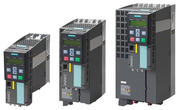
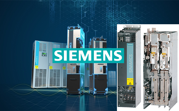
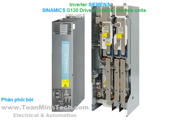
SINAMICS G130 provides a modular drive system for machine builders and plant constructors which permits a drive solution tailored to their applications. SINAMICS G130 consists of two modular, stand-alone components:
- Power Module and
- Control Unit.
The units can be located separately or combined together. The power module contains a space for the control unit.
The user-friendly AOP30 operator panel is available for start-up and local operation. Predefined interfaces, either via a terminal block or PROFIBUS, facilitate drive start-up and control. The interfaces of the control unit can be supplemented by additional modules.

- Particularly quiet and compact converters using state-of-the-art IGBT power semiconductors and innovative cooling solution.
- Maximum servicing friendliness with easy accessibility to all modules.
- Problem-free interfacing into automation solutions using a standard PROFIBUS interface and various analog and digital interfaces.
- Increase in plant availability through easy, fast replacement of individual modules and power components.
- Simple start-up and parameterization using interactive menus on the user-friendly AOP30 operator panel with LCD incorporating graphics capability and plain text display.
- Pumps, fans, compressors
- Moving: Belt conveyors
- Processing: Mills, mixers, kneaders, crushers, agitators, rotary furnaces, extruders
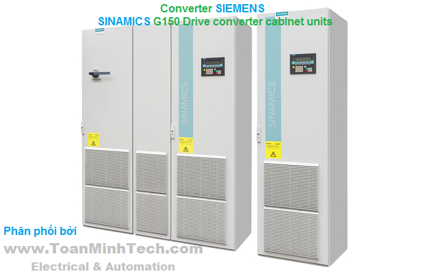
- Branch Chemical IndustryThe SINAMICS G130 is a converter that can be combined very flexibly with the associated system components and installed into customer-specific control cabinets or directly into machines.
SINAMICS G130 converter built-in units are available for the following voltages and power ratings:
|
Line voltage |
Power |
|---|---|
|
380 ... 480 V 3 AC |
110 ... 560 kW |
|
500 ... 600 V 3 AC |
110 ... 560 kW |
|
660 ... 690 V 3 AC |
75 ... 800 kW |
A wide range of add-on electrical components allow the drive system to be optimized for specific requirements. Configuration and commissioning are greatly simplified by predefined interfaces.
The control accuracy of the sensorless vector control is suitable for most applications, which means that an additional actual speed value encoder is not required.
However, encoder evaluation units are available for the SINAMICS G130 converters so that they can address applications that require an encoder for plant-specific reasons.
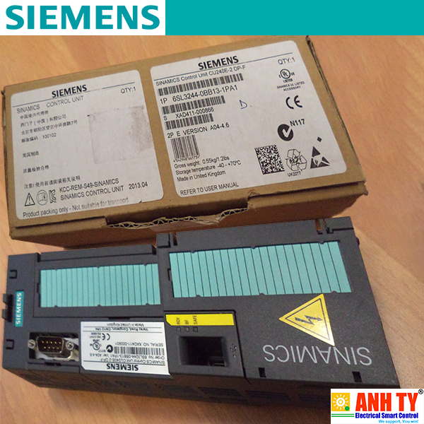
Communication between the Control Unit, the Power Module and other active SINAMICS components is performed via DRIVE-CLiQ, the drive's internal interface. The DRIVE-CLiQ connections, which are available as pre-assembled cables of different lengths, allow a complete converter system to be put together quickly.
For communication with the process control system, with the CU320‑2 Control Unit either a PROFIBUS or a PROFINET interface is available as standard. The interface can also be expanded with digital and analog inputs and outputs. The TM31 Terminal Module and TB30 Terminal Board are provided for this purpose. Additional expansion cards can also be installed to allow communication via CANopen or EtherNet/IP.
Benefits
Particularly quiet and compact converters due to the use of state-of-the-art IGBT power semiconductors and an innovative cooling concept.
Individual modules and power components can be replaced quickly and easily, which ensures a higher level of plant availability. Replaceable components have been designed so that they can be quickly and easily replaced. In addition, the "Spares On Web" Internet tool makes it easy to view the spare parts that are available for the particular order (http://www.siemens.com/sow).
Easily integration in automation solutions by means of a standard communications interface as well as a range of analog and digital interfaces.
Simple commissioning and parameterization using interactive menus on the AOP30 Advanced Operator Panel with graphic LCD and plain-text display, or PC-supported using the STARTER commissioning tool (http://www.siemens.com/starter).
Preset software functions make it easier to adapt the converter to the individual plant.
All components, from individual parts to the ready-to-connect cabinet, undergo rigorous testing throughout the entire production process. This guarantees a high level of functional reliability during installation and commissioning, as well as in operation.
Application
Variable-speed drives are ideal for all applications that involve moving, conveying, pumping or compressing solids, liquids or gases.
Key applications include:
Pumps and fans
Compressors
Extruders and mixers
Mills
Design
The SINAMICS G130 converter built-in units provide machine builders and plant constructors with a modular drive system that can be tailored to specific applications.
SINAMICS G130 converter built-in units mainly consist of the following modular, stand-alone components:
Power Module
Control Unit
They may be located separately from one another or combined in a single unit. The Power Module contains a slot for the Control Unit.
The Power Modules are supplied with a DRIVE-CLiQ cable for communication and a cable for the 24 V supply to the Control Unit. These cables are pre-assembled for installing the Control Unit in the Power Module. If the two units are installed in separate locations, the cables must be ordered in the appropriate lengths.
The AOP30 Advanced Operator Panel and the numeric BOP20 Basic Operator Panel can be used for commissioning and local operation.
Predefined interfaces, via terminal block or the CU320‑2 Control Unit with either PROFIBUS or PROFINET, make commissioning and control of the drive much easier. The interfaces of the CU320‑2 Control Unit can be supplemented with add-on modules, such as the plug-in TB30 Terminal Board or the TM31 Terminal Module.
If further customer interfaces are required for the communication with the drive, an external 24 V supply must be provided.
The following two figures provide assistance when assembling the required converter components. The first figure shows the design and individual components of a SINAMICS G130 drive. The second figure is a flowchart containing the decision and selection criteria required for the individual components.


Coated modules
The following converter components are equipped as standard with coated modules:
Power Modules
Control Units
Sensor Modules
Terminal Modules
Advanced Operator Panel (AOP30)
The coating on the modules protects the sensitive SMD components against corrosive gases, chemically active dust and moisture.
Nickel-plated busbars
All copper busbars of the Power Modules are nickel-plated in order to achieve the best possible immunity to environmental effects. The bare copper connections also do not have to be cleaned for customer connections.
A PROFIBUS or PROFINET communication interface is provided as standard on the CU320‑2 Control Unit for use as a customer interface to the controller; there are also expansions such as the TM31 Terminal Module, the TB30 Terminal Board and modules to support CANopen or EtherNet/IP communication.
These interfaces can be used to connect the system to the higher-level controller using analog and digital signals, or to connect additional devices.
To simplify configuration and commissioning of the drive, the TM31 Terminal Module can be preset with a variety of factory settings.
For further information, please refer to the SINAMICS Low Voltage Engineering Manual.
The converter control contains a high-quality vector control with speed and current control as well as motor and converter protection.
The software functions available as standard are described below:
|
Software and protective functions |
Description |
|---|---|
|
Setpoint specification |
The setpoint can be specified both internally and externally; internally as a fixed setpoint, motorized potentiometer setpoint or jog setpoint, externally via the communications interface or an analog input on the customer terminal block. The internal fixed setpoint and the motorized potentiometer setpoint can be switched or adjusted via control commands from any interface. |
|
Motor identification |
The automatic motor identification function makes commissioning faster and easier and optimizes closed-loop control of the drive. |
|
Ramp-function generator |
A user-friendly ramp-function generator with separately adjustable ramp-up and ramp-down times, together with adjustable rounding times in the lower and upper speed ranges, allows the drive to be smoothly accelerated and braked. As a consequence, this avoids the drive train from being overloaded and reduces the stress on mechanical components. The down ramps can be parameterized separately for quick stop. |
|
Vdc max controller |
The Vdc max controller automatically prevents overvoltages in the DC link, if the set down ramp is too short, for example. This may also extend the set ramp-down time. |
|
Vdc_min control |
For brief line supply failures, the kinetic energy of the rotating drive is used to buffer the DC link and therefore prevents fault trips. The converter remains operational as long as the drive can provide regenerative energy as a result of its motion and the DC-link voltage does not drop below the shutdown threshold. When the line supply recovers within this time, the drive is again accelerated up to its speed setpoint. |
|
Automatic restart 1) |
The automatic restart switches the drive on again when the power is restored after a power failure, and ramps up to the current speed setpoint. |
|
Flying restart 1) |
The flying restart function allows the converter to be switched to a motor that is still turning. With the voltage sensing capability provided by the optional VSM10 Voltage Sensing Module, the flying restart time for large induction motors can be significantly reduced because the motor does not need to be de-magnetized. |
|
Technology controller |
The technology controller function module allows simple control functions to be implemented, e.g. level control or volumetric flow control. The technology controller is designed as a PID controller. The differentiator can be switched to the control deviation channel or to the actual value channel (factory setting). The P, I, and D components can be set separately. |
|
Free function blocks |
Using the freely programmable function blocks, it is easy to implement logic and arithmetic functions for controlling the SINAMICS G130. The blocks can be programmed by means of an operator panel or the STARTER commissioning tool. |
|
Drive Control Chart (DCC) |
Drive Control Chart (DCC) is an additional tool for the easy configuration of technology functions for the SINAMICS G130. The block library contains a large selection of control, arithmetic and logic blocks as well as extensive open-loop and closed-loop control functions. The user-friendly DCC editor enables easy graphics-based configuration, allows control loop structures to be clearly represented and provides a high degree of reusability of charts that have already been created. DCC is an add-on to the STARTER commissioning tool. |
|
I²t detection for motor protection |
A motor model stored in the converter software calculates the motor temperature based on the current speed and load. More exact measurement of the temperature, which also takes into account the influence of the ambient temperature, is possible by means of direct temperature measurement using KTY84 sensors in the motor winding. |
|
Motor temperature evaluation |
Motor protection by evaluating a KTY84, PTC or Pt100 temperature sensor. When a KTY84 sensor is connected, the limit values can be set for alarm or shutdown. When a PTC thermistor is connected, the system reaction to triggering of the thermistor (alarm or trip) can be defined. |
|
Motor blocking protection |
A blocked motor is detected and protected against thermal overloading by a fault trip. |
|
Essential service mode |
Special converter operating mode that increases the availability of the drive system, e.g. in the event of a fire. |
|
Bypass |
This circuit allows the motor to be operated via the converter or directly on the line supply. |
|
Brake control |
"Simple brake control" for control of holding brakes: "Extended brake control" function module for complex brake control, e.g. for motor holding brakes and operational brakes: |
|
Write protection |
Write protection to prevent unintentional changing of the setting parameters (without password function). |
|
Know-how protection |
Know-how protection for encrypting stored data, e.g. to protect configuration know-how, and to protect against changes and duplication (with password function). |
|
Web server |
The integrated web server provides information about the drive unit via its web pages. The web server is accessed using an Internet browser via unsecured (http) or secured transmission (https). |
|
Power unit protection |
Description |
|
Ground fault monitoring at the output |
A ground fault at the output is detected by a total current monitor and results in shutdown in grounded systems. |
|
Electronic short-circuit protection at the output |
A short-circuit at the output (e.g. at the converter output terminals, in the motor cable or in the motor terminal box) is detected and the converter shuts down with a "fault". |
|
Thermal overload protection |
An alarm is issued first when the overtemperature threshold responds. If the temperature rises further, the device either shuts down or independently adjusts the pulse frequency or output current so that a reduction in the thermal load is achieved. Once the cause of the fault has been eliminated (e.g. cooling has been improved), the original operating values are automatically resumed. |
1) Factory setting: Not activated (can be parameterized).
The most important directives and standards are listed below. These are used as basis for the SINAMICS G130 converter built-in units and they must be carefully observed to achieve an EMC-compliant configuration that is safe both functionally and in operation.
|
European directives |
|
|
2006/95/EC |
Low-voltage directive: Directive of the European Parliament and Council of December 12, 2006, on the approximation of the laws of the member states relating to electrical equipment designed for use within certain voltage limits |
|
2006/42/EC |
Machinery directive: Directive of the European Parliament and Council of May 17, 2006 on machinery and for changing Directive 95/16/EC (amendment) |
|
2004/108/EC |
EMC directive: Directive of the European Parliament and Council of December 15, 2004, which repeals directive 89/336/EEC, on the approximation of laws of the member states relating to electromagnetic compatibility |
|
European standards |
|
|
EN ISO 3744 |
Acoustics – Determination of the sound power level and sound energy level for noise sources that result from sound pressure measurements – envelope surface procedure of the accuracy class 2 for a largely free sound field over a reflecting plane |
|
EN ISO 13849-1 |
Safety of machinery – Safety-related parts of control systems Part 1: General design principles (ISO 13849‑1:2006) (replaced EN 954‑1) |
|
EN 60146-1-1 |
Semiconductor converters – General requirements and line-commutated converters Part 1-1: Specification of basic requirements |
|
EN 60204-1 |
Electrical equipment of machines Part 1: General definitions |
|
EN 60529 |
Degrees of protection provided by enclosures (IP code) |
|
EN 61508-1 |
Functional safety of electrical/electronic/programmable electronic safety-related systems Part 1: General requirements |
|
EN 61800-2 |
Adjustable speed electrical power drive systems Part 2: General requirements – Rating specifications for the measurement of low-voltage adjustable frequency AC power drive systems |
|
EN 61800-3 |
Adjustable speed electrical power drive systems Part 3: EMC product standard including special test procedure |
|
EN 61800-5-1 |
Adjustable speed electrical power drive systems Part 5: Safety requirements Main section 1: Electrical and thermal requirements |
|
EN 61800-5-2 |
Adjustable speed electrical power drive systems Part 5-2: Safety requirements – Functional safety (IEC 61800‑5‑2:2007) |
|
North American standards |
|
|
UL508A |
Industrial Control Panels |
|
UL508C |
Power Conversion Equipment |
|
CSA C22.2 No. 14 |
Industrial Control Equipment |
|
Approvals |
|
|
cULus, cURus |
Testing by UL (Underwriters Laboratories, http://www.ul.com) according to UL and CSA standards |
Certification marks: (see Approvals)
|
General technical specifications |
|||
|---|---|---|---|
|
Electrical specifications |
|||
|
Line voltages and power ranges |
|
||
|
Line system configurations |
Grounded TN/TT systems or ungrounded IT systems (a grounded line conductor is not permissible in 690 V line supplies) |
||
|
Line frequency |
47 ... 63 Hz |
||
|
Output frequency |
0 ... 550 Hz1) |
||
|
Line power factor |
|
||
|
> 0.96 |
||
|
0.75 ... 0.93 |
||
|
Efficiency |
> 98% |
||
|
Overvoltage category |
III according to EN 61800‑5‑1 |
||
|
Rated short-circuit current according to IEC, in conjunction with the specified fuses |
|
||
|
65 kA |
||
|
84 kA |
||
|
170 kA |
||
|
200 kA |
||
|
Rated short-circuit current SCCR (Short Circuit Current Rating) according to UL508C (up to 600 V), in conjunction with the specified fuses or circuit breakers |
|
||
|
65 kA |
||
|
84 kA |
||
|
170 kA |
||
|
200 kA |
||
|
Control method |
Vector control with and without encoder or V/f control |
||
|
Fixed speeds |
15 fixed speeds plus 1 minimum speed, parameterizable |
||
|
Speed ranges that can be skipped |
4, parameterizable |
||
|
Setpoint resolution |
0.001 rpm digital 12-bit analog |
||
|
Braking operation |
By means of additional Braking Modules and braking resistors |
||
|
Mechanical specifications |
|||
|
Degree of protection |
IP00 or IP20 depending on type |
||
|
Protection class |
I according to EN 61800‑5‑1 |
||
|
Touch protection |
EN 50274 / BGV A3 when used for the intended purpose |
||
|
Cooling method |
Forced air cooling AF according to EN 60146 |
||
|
Ambient conditions |
Storage |
Transport |
Operation |
|
Ambient temperature |
-25 ... +55 °C |
‑25 ... +70 °C as of ‑40 °C for 24 hours |
0 ... +40 °C up to +55 °C see derating data |
|
Relative humidity (condensation not permissible) |
5 ... 95% |
5 ... 95% |
5 ... 95% |
|
Class 1K4 according to EN 60721‑3‑1 |
Class 2K3 according to EN 60721‑3‑2 |
Class 3K3 according to EN 60721‑3‑3 |
|
|
Environmental class / harmful chemical substances |
Class 1C2 according to EN 60721‑3‑1 |
Class 2C2 according to EN 60721‑3‑2 |
Class 3C2 according to EN 60721‑3‑3 |
|
Organic/biological influences |
Class 1B1 according to EN 60721‑3‑1 |
Class 2B1 according to EN 60721‑3‑2 |
Class 3B1 according to EN 60721‑3‑3 |
|
Degree of pollution |
2 according to EN 61800‑5‑1 |
||
|
Installation altitude |
Up to 2000 m above sea level without derating; > 2000 m see derating data |
||
|
Mechanical stability |
Storage |
Transport |
Operation |
|
Vibratory load |
|
|
|
|
1.5 mm at 5 ... 9 Hz |
3.1 mm at 5 ... 9 Hz |
0.075 mm at 10 ... 58 Hz |
|
5 m/s2 at > 9 ... 200 Hz |
10 m/s2 at > 9 ... 200 Hz |
10 m/s2 at > 58 … 200 Hz |
|
|
Class 1M2 according to EN 60721‑3‑1 |
Class 2M2 according to EN 60721‑3‑2 |
– |
|
Shock load |
|
|
|
|
40 m/s2 for 22 ms |
100 m/s2 for 11 ms |
100 m/s2 for 11 ms |
|
|
Class 1M2 according to EN 60721‑3‑1 |
Class 2M2 according to EN 60721‑3‑2 |
Class 3M4 according to EN 60721‑3‑3 |
|
Compliance with standards |
|||
|
CE marking |
According to EMC Directive No. 2004/108/EC and Low Voltage Directive No. 2006/95/EC and Machinery Directive No. 2006/42/EC for functional safety. |
||
|
Radio interference suppression |
The SINAMICS G130 converter systems are not designed for connection to the public power network ("first environment"). Radio interference suppression is compliant with the EMC product standard for variable-speed drives EN 61800‑3, "Second environment" (industrial networks). EMC disturbances can occur when connected to the public power networks. However, if additional measures are taken (e.g. line filter), it can also be operated in the "first environment". 2) |
||
|
Approvals |
cULus (only for 380 ... 480 V 3 AC and 500 ... 600 V 3 AC) |
||
Deviations from the specified classes are underlined.
1) The output frequency is also affected by the selected control method and the pulse frequency. For further information, please refer to the SINAMICS Low Voltage Engineering Manual.
2) Applies to motor cable lengths < 100 m.
SINAMICS G130 built-in units and the associated system components are rated for an ambient temperature of 40 °C and installation altitudes up to 2000 m above sea level.
At ambient temperatures > 40 °C, the output current must be reduced. Ambient temperatures above 55 °C are not permissible.
At installation altitudes > 2000 m above sea level, it must be taken into account that the air pressure, and therefore air density, decreases as the height increases. As a consequence, the cooling efficiency and the insulation capacity of the air also decrease.
Due to the reduced cooling efficiency, it is necessary, on the one hand, to reduce the ambient temperature and on the other hand, to reduce the heat loss in the built-in unit by reducing the output current, whereby ambient temperatures lower than 40 °C may be offset to compensate.
The following table lists the permissible output currents depending on the installation altitude and ambient temperature. The specified values already include a permitted compensation in respect of installation altitude and ambient temperatures < 40 °C (temperature at the air intake of the built-in unit).
The values apply under the precondition that a cooling air flow through the devices is guaranteed as specified in the technical specifications.
As additional measure for installation altitudes from 2000 m up to 5000 m, an isolating transformer is required in order to reduce transient overvoltages according to EN 60664‑1.
For further information, please refer to the SINAMICS Low Voltage Engineering Manual.
Current derating factors for built-in units depending on the ambient / air intake temperature and the installation altitude
|
Installation altitude above sea level |
Current derating factor (as a percentage of the rated current) |
|||||||
|---|---|---|---|---|---|---|---|---|
|
m |
20 °C |
25 °C |
30 °C |
35 °C |
40 °C |
45 °C |
50 °C |
55 °C |
|
0 ... 2000 |
100% |
100% |
100% |
100% |
100% |
93.3% |
86.7% |
80% |
|
2001 ... 2500 |
100% |
100% |
100% |
100% |
96.3% |
|
|
|
|
2501 ... 3000 |
100% |
100% |
100% |
98.7% |
|
|
|
|
|
3001 ... 3500 |
100% |
100% |
100% |
|
|
|
|
|
|
3501 ... 4000 |
100% |
100% |
96.3% |
|
|
|
|
|
|
4001 ... 4500 |
100% |
97.5% |
|
|
|
|
|
|
|
4501 ... 5000 |
98.2% |
|
|
|
|
|
|
|
Current derating depending on the pulse frequency
To reduce motor noise or to increase output frequency, the pulse frequency can be increased relative to the factory setting (1.25 kHz or 2 kHz). When the pulse frequency is increased, the derating factor of the output current must be taken into account. This derating factor must be applied to the currents specified in the technical specifications.
For further information, please refer to the SINAMICS Low Voltage Engineering Manual.
Derating factor of the output current depending on the pulse frequency for devices with a rated pulse frequency of 2 kHz
|
Article No. |
Type rating |
Output current at 2 kHz |
Derating factor for pulse frequency |
||||
|---|---|---|---|---|---|---|---|
|
6SL3310-... |
kW |
A |
2.5 kHz |
4 kHz |
5 kHz |
7.5 kHz |
8 kHz |
|
380 ... 480 V 3 AC |
|||||||
|
1GE32-1AA3 |
110 |
210 |
95% |
82% |
74% |
54% |
50% |
|
1GE32-6AA3 |
132 |
260 |
95% |
83% |
74% |
54% |
50% |
|
1GE33-1AA3 |
160 |
310 |
97% |
88% |
78% |
54% |
50% |
|
1GE33-8AA3 |
200 |
380 |
96% |
87% |
77% |
54% |
50% |
|
1GE35-0AA3 |
250 |
490 |
94% |
78% |
71% |
53% |
50 |
Derating factor of the output current depending on the pulse frequency for devices with a rated pulse frequency of 1.25 kHz