dienelectrics@gmail.com
 0909186879 dienelectrics@gmail.com
- The same drilling template for all power ratings, using Totally Integrated Automation (TIA), integrated and unified from SINAMICS to the automation level
|
Voltage and power ranges |
3-ph. 380 V - 500 V AC ±10% - 0.75 kW up to 7.5 kW |
|
Types of control |
V/f, FCC |
|
degree of protection |
IP65 |
SINAMICS G110D is suitable for the open-loop of induction motors in a wide range of industrial applications. The SINAMICS G110D is optimized for use in conveyor-related plants and systems, in which a drive is operated in a distributed configuration connected to AS-i or locally without a bus system. The SINAMICS G110D can also be connected to Profibus via the DP/AS-i Link. The SINAMICS G110D inverter is especially suitable for conveyor-related applications, e.g. in airports and in distribution logistics. Further, the inverter can also be used in applications that require an AS-Interface link, only a low number of sensors or basic closed-loop process control.
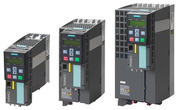
Siemens offers an innovative portfolio of inverters to optimally implement distributed drive solutions. The strengths of the individual members of the drive family permit simple adaptation to the widest range of application demands:
- Identical connection systemsProducts from the family of distributed drives:
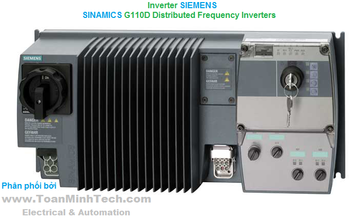
- SINAMICS G110D invertersSINAMICS G110D is a compact inverter in IP65 degree of protection where the Control Unit (CU) and Power Module (PM) function units are combined in one device.
The closed-loop control electronics controls and monitors the power electronics and the connected motor in several different control types that can be selected. The digital inputs and analog inputs on the device mean that sensors can be simply and directly connected at the drive. The input signals can either be directly linked within the closed-loop control or they can be transferred to the central control via AS-Interface for further processing within the context of the overall plant.
The power electronics supplies the motor in the power range from 0.75 kW to 7.5 kW (1 hp to 10 hp). It is controlled (open-loop) from the microprocessor-based control. State-of-the-art IGBT technology with pulse-width-modulation is used for highly reliable and flexible motor operation. Comprehensive protection functions provide a high degree of protection for the inverter and motor. The unusually low profile mechanical design is optimized so that the device can be directly used in the plant or system. The compact inverter has the same drilling dimensions for all power ratings (standard footprint). Further, the dimensions are identical to those of the SINAMICS G120D inverter. This significantly simplifies the mechanical design, installation and retrofit of a system.
The latest technical documentation (catalogs, dimension drawings, certificates, manuals and operating instructions), are available in the Internet at the following address:
http://www.siemens.com/sinamics-g110d/documentation
and offline in the DT Configurator integrated in Catalog CA 01 as an add-on on DVD‑ROM. In addition, the DT Configurator can be used on the Internet without requiring any installation. The DT Configurator can be found in the Siemens Industry Mall at the following address:
http://www.siemens.com/dt-configurator
The STARTER commissioning tool (V4.1.3 and higher) allows menu-prompted commissioning and maintenance of SINAMICS G110D inverters. The operator guidance combined with comprehensive, user-friendly functions for the relevant drive solution allow you to commission the device quickly and easily.
|
Rated power 1) |
Rated output current 2) |
Input current |
Frame size |
SINAMICS G110D |
SINAMICS G110D |
|
|---|---|---|---|---|---|---|
|
kW |
hp |
A |
A |
(Frame size) |
Article No. |
Article No. |
|
380 … 500 V 3 AC3) |
||||||
|
0.75 |
1 |
2.3 |
2 |
FSA |
6SL3511-0PE17-5AM0 |
6SL3511-1PE17-5AM0 |
|
1.5 |
1.5 4) |
4.3 |
3.8 |
FSA |
6SL3511-0PE21-5AM0 |
6SL3511-1PE21-5AM0 |
|
3 |
4 |
7.7 |
7 |
FSA |
6SL3511-0PE23-0AM0 |
6SL3511-1PE23-0AM0 |
|
4 |
5 |
10.2 |
9.1 |
FSB |
6SL3511-0PE24-0AM0 |
6SL3511-1PE24-0AM0 |
|
5.5 |
7.5 |
13.2 |
12.2 |
FSC |
6SL3511-0PE25-5AM0 |
6SL3511-1PE25-5AM0 |
|
7.5 |
10 |
19 |
17.9 |
FSC |
6SL3511-0PE27-5AM0 |
6SL3511-1PE27-5AM0 |
1) Rated power based on the rated output current Irated. The rated output current Irated is based on the duty cycle for high overload (HO).
2) The rated output current Irated is based on the duty cycle for high overload (HO). These current values apply at 400 V and are specified on the rating plate.
3) With the exception of UL operation, 500 V +10 % is possible.
4) It is not possible to make any assignment to a particular standard.
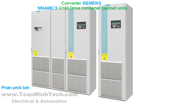
The SINAMICS G110D distributed inverters are compact frequency inverters for standard drives. Each SINAMICS G110D includes both the Control Unit as well as the Power Module in one unit.

SINAMICS G110D with integrated maintenance switch and manual local control with keyswitch
SINAMICS G110D features an integrated brake chopper and is suitable for distributed drives without energy recovery capability. If generator energy is produced then this is dissipated in the externally connected braking resistors. The communication is realized via the local inputs (digital and analog) or via the AS-Interface bus integrated as standard.

SINAMICS G110D with integrated maintenance switch
The inverter is available in two versions: With and without maintenance switch. Thanks to the optional maintenance switch (this cannot be retrofitted), when service is required, the inverter can be simply disconnected from the line supply without having to have any additional components or additional wiring costs when configuring.
Braking resistors
Excess energy in the DC link is dissipated in the braking resistors. The braking resistors are designed for use with the SINAMICS G110D. This has an integrated brake chopper (electronic switch).
Intelligent Operator Panel IOP Handheld
User-friendly and powerful operator panel for commissioning and diagnostics as well as local operator control and monitoring of SINAMICS G110D.
Manual local control with keyswitch
Master control can be toggled between automatic mode (PLC) and manual local mode using the manual local control. This can also be used to switch off the inverter. Additional functions include switching over between continuous and jog mode, starting the motor including direction of rotation and deactivating the quick stop in the manual mode.
Memory card
The parameter settings for an inverter can be stored on the SINAMICS SD card. When service is required, e.g. after the inverter has been replaced and the data have been downloaded from the memory card, the drive system is immediately ready for use again. The associated memory card holder is not included in the scope of supply of the inverter and must be separately ordered.
Card holder for memory card
To use the SINAMICS SD memory card, a card holder is required that is inserted under the blanking cover or under the manual/automatic control operator panel on the inverter.
RS232 interface cable for communication with a PC
For controlling and commissioning an inverter directly from a PC if the appropriate software (STARTER commissioning tool V4.1.3 and higher) has been installed.
USB interface cable for communication with a PC
For controlling and commissioning an inverter directly from a PC if the appropriate software (STARTER commissioning tool V4.1.3 and higher) has been installed.
Adapter for mounting the SINAMICS G110D instead of a SIRIUS M200D motor starter
Connection board kit to mount a SINAMICS G110D inverter on the connection holes of the SIRIUS M200D motor starter (assuming that there is enough space).
Connector kit for braking resistor
Connector kit for using or connecting different braking resistors.
UL connector kit
Special UL connector kit for UL-compatible applications.
Protection bar
Protection bar for protecting the connector against shearing due to mechanical stress
Connecting cable
Connector sets to connect to the line supply and the outgoing motor feeder are available as accessories as well as pre-assembled motor cables for connection to the motor.
Flexible plug-in cables to transfer data between AS-Interface participants as well as to supply the Control Unit and the Power Module with power.
Spare Parts Kit
A Spare Parts Kit is available which comprises small parts such as seals, caps and screws.
Replacement fan
A replacement fan is available, which comprises a pre-mounted unit with cover, fan and screws.
The SINAMICS G110D distributed inverters have, as standard, the following interfaces:
- Motor connection via HAN Q8 (connector) including control of the motor brake and temperature sensorThe interfaces are identical to those of the SINAMICS G120D distributed inverter and those of the SIRIUS M200D motor starter.

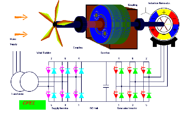
Connection diagram for SINAMICS G110D with integrated line filter class A
The following electronic configuring aids and engineering tools are available for the SINAMICS G110D distributed inverters:
The interactive catalog CA 01 – the offline Industry Mall of Siemens on DVD‑ROM – contains over 100 000 products with approximately 5 million possible drive system product variants. The Drive Technology Configurator (DT Configurator) has been developed to facilitate selection of the correct motor and/or inverter from the wide spectrum of drives. It is integrated in Catalog CA 01 as an add-on on DVD‑ROM.
In addition, the DT Configurator can be used on the Internet without requiring any installation. The DT Configurator can be found in the Siemens Industry Mall at the following address:
http://www.siemens.com/dt-configurator
The STARTER commissioning tool allows menu-prompted commissioning, optimization and diagnostics. Apart from the SINAMICS drives, STARTER is also suitable for the MICROMASTER 4 devices and for SINAMICS G110D with STARTER V4.1.3 and higher.
You can find further information about the STARTER commissioning tool in the chapter Engineering tools.
Additional information about the STARTER commissioning tool is available on the Internet at
http://www.siemens.com/starter
Drive ES is the engineering system that can be used to integrate the communication, configuration and data management functions of Siemens drive technology into the SIMATIC automation world easily, efficiently and cost-effectively. Two software packages are available for SINAMICS – Drive ES Basic and Drive ES PCS.
You can find further information about the Drive ES engineering system in the chapter Engineering tools.
Additional information about the Drive ES engineering system is available on the Internet at
http://www.siemens.com/drive-es
Unless explicitly specified otherwise, the following technical specifications are valid for all SINAMICS G110D distributed inverters.
|
General technical specifications |
|
|---|---|
|
Mechanical specifications |
|
|
Vibratory load |
|
|
Class 1M2 |
|
Class 3M2 |
|
Shock load |
|
|
Class 1M2 |
|
Class 3M2 |
|
Ambient conditions |
|
|
Degree of protection |
IP65/UL Type 3 |
|
Protection class According to EN 61800‑5‑1 |
Class III (PELV) |
|
Touch protection According to EN 61800‑5‑1 |
Class I (with protective conductor system) |
|
Humidity, max. |
95 % at 40 °C (104 °F) |
|
Ambient temperature |
|
|
-40 ... +70 °C (-40 ... +158 °F) |
|
-40 ... +70 °C (-40 ... +158 °F) |
|
-10 ... +40 °C (14 ... +104 °F) without derating |
|
Environmental class/harmful chemical substances |
|
|
Class 3C2 |
|
Degree of pollution According to EN 61800‑5‑1 |
2 |
|
Standards |
|
|
Compliance with standards |
UL 508C (UL list number E121068), CE, C-Tick |
|
CE marking, according to |
Low-Voltage Directive 2006/95/EC |
|
EMC Directive 2) |
|
|
Category C2 3) according to EN 61800‑3 |
|
|
Note: The EMC product standard EN 61800-3 does not apply directly to a frequency inverter but to a PDS (Power Drive System), which comprises the complete circuitry, motor and cables in addition to the inverter. The frequency inverters on their own do not generally require identification according to the EMC Directive. |
1) In product packaging.
2) For further general information see also chapter SINAMICS G120, Technical specifications, Compliance with standards.
3) With shielded motor cable up to 15 m (49 ft).
|
Technical specifications, control electronics |
|
|---|---|
|
Electrical specifications |
|
|
Operating voltage |
External 24 V DC necessary |
|
Current consumption, max. 1) (from the non-switched 24 V DC supply, yellow AS-Interface cable) |
320 mA |
|
Current consumption, max. (from the switched 24 V DC supply, black AS-Interface cable) |
|
|
180 mA |
|
350 mA |
|
Fixed frequencies |
6, parameterizable |
|
Interfaces |
|
|
Digital inputs |
4 |
|
Analog inputs (0 ... 10 V) |
1 |
|
Bus interface |
AS-Interface |
|
PTC/KTY interface |
Connection via Power Modules |
|
1 input, |
|
Control of a mechanical motor brake |
Connection via Power Modules |
|
Memory card slot |
Optional |
|
RS232 interface |
Connection with RS232 interface cable via the optical inverter interface |
|
USB interface |
Connection with USB interface cable via the optical inverter interface |
|
Open-loop/closed-loop control technique and software |
|
|
V/f linear/quadratic/parameterizable |
✓ |
|
V/f with flux current control (FCC) |
✓ |
|
Software functions |
|
1) Includes the current consumption of connected sensors. Analog input as voltage input, 0 V to 10 V.
|
General technical specifications, power electronics |
||||||
|---|---|---|---|---|---|---|
|
System operating voltage |
380 ... 500 V AC 3 AC ±10 % |
|||||
|
Grid requirement, short-circuit power RSC |
No restriction |
|||||
|
Input frequency |
47 ... 63 Hz |
|||||
|
Output frequency |
|
|||||
|
0 ... 550 Hz1) |
|||||
|
Pulse frequency |
4 kHz (standard), for higher pulse frequencies up to 16 kHz, see derating data |
|||||
|
Power factor λ |
0.7 ... 0.85 |
|||||
|
Inverter efficiency η |
95% |
|||||
|
Output voltage, max. as % of input voltage |
0 ... 87% |
|||||
|
Overload capability |
|
|||||
|
|
|||||
|
Electromagnetic compatibility |
Integrated class A line filter according to EN 55011 |
|||||
|
Possible braking methods |
DC braking |
|||||
|
Line voltage |
380 V AC |
400 V AC |
440 V AC |
480 V AC |
500 V AC |
|
|
Rectified brake voltage |
171 V DC |
180 V DC |
198 V DC |
216 V DC |
225 V DC |
|
|
Recommended brake coil voltage for Siemens motors |
170 ... 200 V DC |
170 ... 200 V DC 184 ... 218 V DC 2) |
184 ... 218 V DC 2) |
184 ... 218 V DC 2) |
- |
|
|
Disconnection on the DC side permits "fast" braking. |
||||||
|
|
|||||
|
Permissible mounting position |
Horizontal wall mounting and mounting in the horizontal position |
|||||
|
Relative humidity |
<95 % RH, condensation not permissible |
|||||
|
Cooling |
|
|||||
|
Installation altitude |
|
|||||
|
Short-Circuit Current Rating SCCR 3) |
40 kA |
|||||
|
Protection functions |
|
|||||
|
Compliance with standards |
UL 508C (UL list number E121068), CE, C-Tick |
|||||
|
CE marking, according to |
Low-Voltage Directive 2006/95/EC |
|||||
1) For further information see http://support.automation.siemens.com/WW/view/de/107669667
2) With voltage boost activated.
3) Applies to industrial control panel installations to NEC article 409 or UL 508A.
|
Line voltage |
SINAMICS G110D |
||||||
|---|---|---|---|---|---|---|---|
|
|
6SL3511-.PE17-5AM0 |
6SL3511-.PE21-5AM0 |
6SL3511-.PE23-0AM0 |
6SL3511-.PE24-0AM0 |
6SL3511-.PE25-5AM0 |
6SL3511-.PE27-5AM0 |
|
|
Rated output current Irated1) |
A |
2.3 |
4.3 |
7.7 |
10.2 |
13.2 |
19 |
|
Maximum output current Imax |
A |
4.6 |
8.6 |
15.4 |
20.4 |
26.4 |
38 |
|
Rated power |
kW (hp) |
0.75 (1) |
1.5 (2) |
3 (4) |
4 (5) |
5.5 (7.5) |
7.5 (10) |
|
Rated pulse frequency |
kHz |
4 |
4 |
4 |
4 |
4 |
4 |
|
Efficiency η |
% |
95 |
95 |
95 |
95 |
95 |
95 |
|
Power loss 2) At rated output current |
kW |
0.044 |
0.068 |
0.105 |
0.168 |
0.196 |
0.261 |
|
Rated input current 3) |
A |
2 |
3.8 |
7 |
9.1 |
12.2 |
17.9 |
|
Line supply connection U1/L1, V1/L2, W1/L3, PE |
|
HAN Q4/2 (connector) |
HAN Q4/2 (connector) |
HAN Q4/2 (connector) |
HAN Q4/2 (connector) |
HAN Q4/2 (connector) |
HAN Q4/2 (connector) |
|
mm2 |
1.5 ... 6 |
1.5 ... 6 |
2.5 ... 6 |
2.5 ... 6 |
4 ... 6 |
4 ... 6 |
|
Motor connection U2, V2, W2, PE, motor brake, temperature sensor |
|
HAN Q8 (socket) |
HAN Q8 (socket) |
HAN Q8 (socket) |
HAN Q8 (socket) |
HAN Q8 (socket) |
HAN Q8 (socket) |
|
mm2 |
1 ... 4 |
1 ... 4 |
2.5 ... 4 |
2.5 ... 4 |
4 |
4 |
|
Motor cable length, max. |
m (ft) |
15 (49) |
15 (49) |
15 (49) |
15 (49) |
15 (49) |
15 (49) |
|
Degree of protection |
|
IP65 |
IP65 |
IP65 |
IP65 |
IP65 |
IP65 |
|
Dimensions |
|
|
|
|
|
|
|
|
mm (in) |
445 (17.52) |
445 (17.52) |
445 (17.52) |
445 (17.52) |
445 (17.52) |
445 (17.52) |
|
mm (in) |
210 (8.27) |
210 (8.27) |
210 (8.27) |
210 (8.27) |
210 (8.27) |
210 (8.27) |
|
|
|
|
|
|
|
|
|
mm (in) |
125 (4.92) |
125 (4.92) |
125 (4.92) |
165 (6.50) |
240 (9.45) |
240 (9.45) |
|
mm (in) |
145 (5.71) |
145 (5.71) |
145 (5.71) |
165 (6.50) |
240 (9.45) |
240 (9.45) |
|
Frame size |
|
FSA |
FSA |
FSA |
FSB |
FSC |
FSC |
|
Weight, approx. |
|
|
|
|
|
|
|
|
kg (lb) |
6.7 (14.8) |
6.7 (14.8) |
6.9 (15.2) |
7.4 (16.3) |
9.4 (20.7) |
9.5 (20.9) |
|
kg (lb) |
7 (15.4) |
7 (15.4) |
7.2 (15.9) |
7.7 (17) |
9.7 (21.4) |
9.8 (21.6) |
1) The rated output current Irated is based on the duty cycle for high overload (HO).
2) Typical values. You can find additional information on the Internet at http://support.automation.siemens.com/WW/view/de/94059311
3) The input current depends on the motor load and line impedance. The input currents apply for load at rated power for a line impedance corresponding to uK = 1 %.
Pulse frequency
|
Rated power |
Rated output current in A for a pulse frequency of |
|||||||
|---|---|---|---|---|---|---|---|---|
|
kW |
hp |
4 kHz |
6 kHz |
8 kHz |
10 kHz |
12 kHz |
14 kHz |
16 kHz |
|
0.75 |
1 |
2.2 |
1.9 |
1.5 |
1.3 |
1.1 |
1 |
0.9 |
|
1.5 |
1.5 1) |
4.1 |
3.5 |
2.9 |
2.5 |
2.1 |
1.8 |
1.6 |
|
3 |
4 |
7.7 |
6.5 |
5.4 |
4.6 |
3.9 |
3.5 |
3.1 |
|
4 |
5 |
10.2 |
8.7 |
7.1 |
6.1 |
5.1 |
4.6 |
4.1 |
|
5.5 |
7.5 |
13.2 |
11.2 |
9.2 |
7.9 |
6.6 |
5.9 |
5.3 |
|
7.5 |
10 |
19 |
16.2 |
13.3 |
11.4 |
9.5 |
8.6 |
7.6 |
1) It is not possible to make any assignment to a particular standard.

Permissible output current as a function of ambient temperature for frame sizes FSA to FSC

Permissible output current as a function of installation altitude for frame sizes FSA to FSC

Permissible input voltage as a function of installation altitude for frame sizes FSA to FSC
.JPG)
SINAMICS G110D, frame size FSA, with integrated line filter class A

SINAMICS G110D, frame size FSB, with integrated line filter class A

SINAMICS G110D, frame size FSC, with integrated line filter class A
Mounted with 4 M5 studs, 4 M5 nuts, 4 M5 washers.
Ventilation clearance required (for wall mounting) at top and bottom: 150 mm (5.9 inches).
All dimensions in mm (values in brackets are in inches).

SINAMICS G110D, frame size FSA, with integrated line filter class A and maintenance switch

SINAMICS G110D, frame size FSB, with integrated line filter class A and maintenance switch

SINAMICS G110D, frame size FSC, with integrated line filter class A and maintenance switch
Mounted with 4 M5 studs, 4 M5 nuts, 4 M5 washers.
Ventilation clearance required (for wall mounting) at top and bottom: 150 mm (5.9 inches).
All dimensions in mm (values in brackets are in inches).
(Nguyễn Thảo Trường - http://DienElectric.com theo Siemens)