


 dienelectrics@gmail.com
 0909186879 dienelectrics@gmail.com
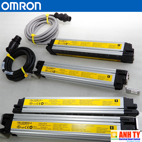


| Application | Detection capability |
Beam gap | Operating range | Protective height (mm) |
Model | |
|---|---|---|---|---|---|---|
| PNP output | NPN output | |||||
| Hand protection | Dia. 25 mm | 20 mm | 0.2 to 7 m | 185 to 1,105 | F3SJ-E[][][][]P25 * | F3SJ-E[][][][]N25 |
Note: F3SJ-E uses a 3 m prewired discrete cable.
*1. For S-mark compatible model, the suffix "-S" is added to the model name.
| Model | Number of beams | Protective height [mm] *2 | |
|---|---|---|---|
| PNP output *1 | NPN output | ||
| F3SJ-E0185P25 | F3SJ-E0185N25 | 8 | 185 |
| F3SJ-E0225P25 | F3SJ-E0225N25 | 10 | 225 |
| F3SJ-E0305P25 | F3SJ-E0305N25 | 14 | 305 |
| F3SJ-E0385P25 | F3SJ-E0385N25 | 18 | 385 |
| F3SJ-E0465P25 | F3SJ-E0465N25 | 22 | 465 |
| F3SJ-E0545P25 | F3SJ-E0545N25 | 26 | 545 |
| F3SJ-E0625P25 | F3SJ-E0625N25 | 30 | 625 |
| F3SJ-E0705P25 | F3SJ-E0705N25 | 34 | 705 |
| F3SJ-E0785P25 | F3SJ-E0785N25 | 38 | 785 |
| F3SJ-E0865P25 | F3SJ-E0865N25 | 42 | 865 |
| F3SJ-E0945P25 | F3SJ-E0945N25 | 46 | 945 |
| F3SJ-E1025P25 | F3SJ-E1025N25 | 50 | 1,025 |
| F3SJ-E1105P25 | F3SJ-E1105N25 | 54 | 1,105 |
*1. For S-mark compatible model, the suffix "-S" is added to the model name.
(Example) F3SJ-E0185P25-S
| Type | Apprnce | Specifications | Model | Remarks |
|---|---|---|---|---|
| G7SA Relays with Forcibly Guided Contacts |
Nodes: 4 Contact type: 2A2B Rated switch load: 250 VAC 6A, 30 VDC 6A |
G7SA-2A2B | For details on other models or socket models, refer to the OMRON's website. |
|
| Nodes: 4 Contact type: 3NO+1NC Rated switch load: 250 VAC 6A, 30 VDC 6A |
G7SA-3A1B | |||
| G7S-[]-E Relays with Forcibly Guided Contacts |
Nodes: 6 Contact type: 4NO+2NC Rated switch load: 250 VAC 10 A, 30 VDC 10 A |
G7S-4A2B-E | For details on other models or socket models, refer to the OMRON's website. |
|
| Nodes: 6 Contact type: 3NO+3NC Rated switch load: 250 VAC 10 A, 30 VDC 10 A |
G7S-3A3B-E |
| Appearance | Output | Model |
|---|---|---|
| Laser Pointer for F3SJ | F39-PTJ |
Spatter Protection Cover (2 covers per set, one for emitter and one for receiver) (10% Operating Range Attenuation)
| Appearance | Model |
|---|---|
| F39-HB[][][][] * |
* The same 4-digit numbers as the protective heights ([][][][] in the light curtain model names) are substituted by in the
model names.
| Appearance | Model | Remarks |
|---|---|---|
| F39-PB[][][][] *1 | 2 Light Curtain brackets 4 mounting brackets 0 to 4 intermediate brackets for backside mounting (quantity required for the sensing width) 0 to 4 intermediate brackets for mounting to the sides (quantity required for the sensing width) |
|
| F39-PB[][][][]-S *1 *2 | 1 Light Curtain bracket 2 mounting brackets 0 to 2 intermediate brackets for backside mounting (quantity required for the sensing width) 0 to 2 intermediate brackets for mounting to the sides (quantity required for the sensing width) |
Note: The following are not provided with the Protective Bars.
• - Safety Light Curtain
| Diameter | Model |
|---|---|
| 14mm dia. | F39-TRD14 |
| 20mm dia. | F39-TRD20 |
| 25mm dia. | F39-TRD25 |
| 30mm dia. | F39-TRD30 |
| Appearance | Applicable light curtain | Column height | Model |
|---|---|---|---|
| F3SJ Series Safety Light Curtain |
|||
(Operating range becomes 15% shorter than the rating) |
Protective height up to 0880 | 990 mm | F39-SML0990 |
| Protective height up to 1200 | 1,310 mm | F39-SML1310 | |
| Protective height up to 1520 | 1,630 mm | F39-SML1630 | |
| Protective height up to 1840 | 1,950 mm | F39-SML1950 |
| Appearance | Specifications | Model | Application | Remarks |
|---|---|---|---|---|
| Top/bottom bracket |
F39-LJB1 | Top/bottom bracket for F3SJ-E/B | 2 for an emitter, 2 for a receiver, total of 4 per set |
|
| Intermediate bracket |
F39-LJB2 *1 *2 | In combination use with top/bottom bracket for F3SJ-E/B Can be used as free-location bracket. |
1 set with 2 pieces | |
| One-touch bracket |
F39-LJB3-M6 *1 | One-touch bracket for F3SJ-E/B Supports M6 slide nut for aluminum frame. |
1 set with 2 pieces | |
| F39-LJB3-M8 *2 | One-touch bracket for F3SJ-E/B Supports M8 slide nut for aluminum frame. |
|||
| One-touch M6 bracket One-touch M8 bracket |
F39-LJB3-M6K *1 | Bracket to mount an intermediate bracket to the aluminum frame with a single touch. |
Hexagon socket head cap screws (M6 x 10) are included. |
|
| F39-LJB3-M8K *2 | Hexagon socket head cap screws (M8 x 14) are included. |
|||
| Compatible mounting bracket |
F39-LJB4 | Mounting bracket used when replacing existing area sensors (F3SJ-A or F3SN) with the F3SJ-E/B. |
2 for an emitter, 2 for a receiver, total of 4 per set |
|
| Contact mount bracket |
F39-LJB5 | Bracket to closely contact the back side of the Sensor. |
2 for an emitter, 2 for a receiver, total of 4 per set |
Note: All the sensor mounting brackets for F3SJ-E are sold separately.
*1. Combining F39-LJB2 and F39-LJB3-M6K makes F39-LJB3-M6.Main Units
| Application | Detection capability |
Beam gap | Operating range |
Protective height (mm) |
Model | |
|---|---|---|---|---|---|---|
| PNP output | NPN output | |||||
| Hand protection | Dia. 25 mm | 20 mm | 0.2 to 7 m | 185 to 2,065 | F3SJ-B[][][][]P25 *1 | F3SJ-B[][][][]N25 |
| Hand protection | Dia. 25 mm | 20 mm | 0.2 to 7 m | 185 to 2,065 | F3SJ-B[][][][]P25-01TS *2 | --- |
| Environmental resistance | Dia. 25 mm | 20 mm | 0.2 to 6 m | 225 to 1,985 | F3SJ-B[][][][]P25-02TS *2 | --- |
*1. For S-mark compatible model, the suffix "-S" is added to the model name. (except for models with the suffix
"-01TS" or "-02TS".)
Please contact our sales representative.
| Model | Number of beams | Protective height [mm] * |
|||
|---|---|---|---|---|---|
| PNP output | NPN output | PNP output | NPN output | ||
| F3SJ-B0185P25 | F3SJ-B0185N25 | F3SJ-B0185P25-01TS | - | 8 | 185 |
| F3SJ-B0225P25 | F3SJ-B0225N25 | F3SJ-B0225P25-01TS | F3SJ-B0225P25-02TS | 10 | 225 |
| F3SJ-B0305P25 | F3SJ-B0305N25 | F3SJ-B0305P25-01TS | F3SJ-B0305P25-02TS | 14 | 305 |
| F3SJ-B0385P25 | F3SJ-B0385N25 | F3SJ-B0385P25-01TS | F3SJ-B0385P25-02TS | 18 | 385 |
| F3SJ-B0465P25 | F3SJ-B0465N25 | F3SJ-B0465P25-01TS | F3SJ-B0465P25-02TS | 22 | 465 |
| F3SJ-B0545P25 | F3SJ-B0545N25 | F3SJ-B0545P25-01TS | F3SJ-B0545P25-02TS | 26 | 545 |
| F3SJ-B0625P25 | F3SJ-B0625N25 | F3SJ-B0625P25-01TS | F3SJ-B0625P25-02TS | 30 | 625 |
| F3SJ-B0705P25 | F3SJ-B0705N25 | F3SJ-B0705P25-01TS | F3SJ-B0705P25-02TS | 34 | 705 |
| F3SJ-B0785P25 | F3SJ-B0785N25 | F3SJ-B0785P25-01TS | F3SJ-B0785P25-02TS | 38 | 785 |
| F3SJ-B0865P25 | F3SJ-B0865N25 | F3SJ-B0865P25-01TS | F3SJ-B0865P25-02TS | 42 | 865 |
| F3SJ-B0945P25 | F3SJ-B0945N25 | F3SJ-B0945P25-01TS | F3SJ-B0945P25-02TS | 46 | 945 |
| F3SJ-B1025P25 | F3SJ-B1025N25 | F3SJ-B1025P25-01TS | F3SJ-B1025P25-02TS | 50 | 1,025 |
| F3SJ-B1105P25 | F3SJ-B1105N25 | F3SJ-B1105P25-01TS | F3SJ-B1105P25-02TS | 54 | 1,105 |
| F3SJ-B1185P25 | F3SJ-B1185N25 | F3SJ-B1185P25-01TS | F3SJ-B1185P25-02TS | 58 | 1,185 |
| F3SJ-B1265P25 | F3SJ-B1265N25 | F3SJ-B1265P25-01TS | F3SJ-B1265P25-02TS | 62 | 1,265 |
| F3SJ-B1345P25 | F3SJ-B1345N25 | F3SJ-B1345P25-01TS | F3SJ-B1345P25-02TS | 66 | 1,345 |
| F3SJ-B1425P25 | F3SJ-B1425N25 | F3SJ-B1425P25-01TS | F3SJ-B1425P25-02TS | 70 | 1,425 |
| F3SJ-B1505P25 | F3SJ-B1505N25 | F3SJ-B1505P25-01TS | F3SJ-B1505P25-02TS | 74 | 1,505 |
| F3SJ-B1585P25 | F3SJ-B1585N25 | F3SJ-B1585P25-01TS | F3SJ-B1585P25-02TS | 78 | 1,585 |
| F3SJ-B1665P25 | F3SJ-B1665N25 | F3SJ-B1665P25-01TS | F3SJ-B1665P25-02TS | 82 | 1,665 |
| F3SJ-B1745P25 | F3SJ-B1745N25 | F3SJ-B1745P25-01TS | F3SJ-B1745P25-02TS | 86 | 1,745 |
| F3SJ-B1825P25 | F3SJ-B1825N25 | F3SJ-B1825P25-01TS | F3SJ-B1825P25-02TS | 90 | 1,825 |
| F3SJ-B1905P25 | F3SJ-B1905N25 | F3SJ-B1905P25-01TS | F3SJ-B1905P25-02TS | 94 | 1,905 |
| F3SJ-B1985P25 | F3SJ-B1985N25 | F3SJ-B1985P25-01TS | F3SJ-B1985P25-02TS | 98 | 1,985 |
| F3SJ-B2065P25 | F3SJ-B2065N25 | F3SJ-B2065P25-01TS | - | 102 | 2,065 |
* Protective height (mm) = Total sensor length
Note: 1. The models with the suffix "-01TS" or "-02TS are the PNP type only.
For wiring with safety circuit such as single safety relay, safety relay unit, and safety controller
| Appearance | Cable length | Specifications | Model |
|---|---|---|---|
| 3 m | M12 connector (8-pin) | F39-JD3A | |
| 7 m | F39-JD7A | ||
| 10 m | F39-JD10A | ||
| 15 m | F39-JD15A | ||
| 20 m | F39-JD20A |
* The cable for emitter and the cable for receiver are available separately. Add '-L' for emitter or '-D' for receiver to the end
of the model number when you order.
Control unit for connection with F3SP-B1P, to extend the length under series connection
| Appearance | Cable length | Specifications | Model |
|---|---|---|---|
| 0.5 m | M12 connector (8-pin) | F39-JDR5B | |
| 1 m | F39-JD1B | ||
| 3 m | F39-JD3B | ||
| 5 m | F39-JD5B | ||
| 7 m | F39-JD7B | ||
| 10 m | F39-JD10B | ||
| 15 m | F39-JD15B | ||
| 20 m | F39-JD20B |
* The cable for emitter and the cable for receiver are available separately. Add '-L' for emitter or '-D' for receiver to the end
of the model number when you order.
Series-connection Cable (2 covers per set, one for emitter and one for receiver)
| Type | Appearance | Cable length | Model | Application |
|---|---|---|---|---|
| Series connection cable for extension |
0.2 m | F39-JBR2W * | For series connection |
* This product is for F3SJ-B only.
Note: The Double-Ended Cable (up to 7 m: F39-JD7B) can be added to extend the cable length between the series-Simple wiring connector system (Order the F39-CN5 and Cables for Simple Wiring.)
| Appearance | Model | Application |
|---|---|---|
| F39-CN5 | To reduce wiring |
| Appearance | Contents | Cable length | Model | |
|---|---|---|---|---|
| Double-Ended Cable | F39-JD3B-L | 3 m | F39-JD0303BA | |
| Single-Ended Cable | F39-JD3A-D | 3 m | ||
| Double-Ended Cable | F39-JD3B-L | 3 m | F39-JD0307BA | |
| Single-Ended Cable | F39-JD7A-D | 7 m | ||
| Double-Ended Cable | F39-JD3B-L | 3 m | F39-JD0310BA | |
| Single-Ended Cable | F39-JD10A-D | 10 m | ||
| Double-Ended Cable | F39-JD5B-L | 5 m | F39-JD0503BA | |
| Single-Ended Cable | F39-JD3A-D | 3 m | ||
| Double-Ended Cable | F39-JD5B-L | 5 m | F39-JD0507BA | |
| Single-Ended Cable | F39-JD7A-D | 7 m | ||
| Double-Ended Cable | F39-JD5B-L | 5 m | F39-JD0510BA | |
| Single-Ended Cable | F39-JD10A-D | 10 m | ||
| Double-Ended Cable | F39-JD10B-L | 10 m | F39-JD1003BA | |
| Single-Ended Cable | F39-JD3A-D | 3 m | ||
| Double-Ended Cable | F39-JD10B-L | 10 m | F39-JD1007BA | |
| Single-Ended Cable | F39-JD7A-D | 7 m | ||
| Double-Ended Cable | F39-JD10B-L | 10 m | F39-JD1010BA | |
| Single-Ended Cable | F39-JD10A-D | 10 m | ||
Note: A double-ended cable and single-ended cable with other cable lengths than those listed above can also be used in
combination.
| Type | Appearance | Specifications | Model | Remarks |
|---|---|---|---|---|
| G7SA Relays with Forcibly Guided Contacts |
Nodes: 4 Contact type: 2NO+2NC Rated switch load: 250 VAC 6A, 30 VDC 6A |
G7SA-2A2B | For details on other models or socket models, refer to the OMRON's website. |
|
| Nodes: 4 Contact type: 3NO+1NC Rated switch load: 250 VAC 6A, 30 VDC 6A |
G7SA-3A1B | |||
| G7S-[]-E Relays with Forcibly Guided Contacts |
Nodes: 6 Contact type: 4NO+2NC Rated switch load: 250 VAC 10 A, 30 VDC 10 A |
G7S-4A2B-E | For details on other models or socket models, refer to the OMRON's website. |
|
| Nodes: 6 Contact type: 3NO+3NC Rated switch load: 250 VAC 10 A, 30 VDC 10 A |
G7S-3A3B-E |
| Diameter | Model |
|---|---|
| 14mm dia. | F39-TRD14 |
| 20mm dia. | F39-TRD20 |
| 25mm dia. | F39-TRD25 |
| 30mm dia. | F39-TRD30 |
(Dedicated PNP output type)
| Appearance | Output | Model | Remarks |
|---|---|---|---|
| Relay, 3NO+1NC | F3SP-B1P * | For connection with F3SJ-B, use a double-ended cable F39-JD[]B. |
* F3SJ for NPN output type cannot be connected.
| Type | Appearance | Specifications | Model | Remarks |
|---|---|---|---|---|
| Connector Terminal Box/ Muting Terminals *2 |
Model with PNP Muting Sensor Output |
F39-TC5P01 | Significantly reduces amount of wiring between Safety Light Curtains and Muting Sensors. IP67 model for mounting at Sensor installation site. For details, refer to the OMRON's website. |
|
| Model with PNP Override Input |
F39-TC5P02 | |||
| Model with NPN Muting Sensor Output |
F39-TC5N01 | |||
| Model with NPN Override Input |
F39-TC5N02 | |||
| Safety Terminal Relays *2 | PNP output relay, SPDT-NO |
F3SP-T01 *1 | Significantly reduces amount of wiring between Safety Light Curtains and Muting Sensors. For details, refer to the OMRON's website. |
*1. F3SJ for NPN output type cannot be connected.
*2. The models with the suffix "-01TS" cannot be connected.
Note: Orders for F39-TC5 Series and F3SP-T01 have been discontinued at the end of May 2020.
| Appearance | Output | Model |
|---|---|---|
| Laser Pointer for F3SJ | F39-PTJ * |
* It cannot be mounted to the models with the suffix "-02TS".
| Appearance | Model |
|---|---|
| F39-HB[][][][] *1 *2 |
*1. The same 4-digit numbers as the protective heights ([][][][] in the light curtain model names) are substituted by in
the model names.
| Appearance | Model | Remarks |
|---|---|---|
| F39-PB[][][][] *1 | 2 Light Curtain brackets 4 mounting brackets 0 to 4 intermediate brackets for backside mounting (quantity required for the sensing width) 0 to 4 intermediate brackets for mounting to the sides (quantity required for the sensing width) |
|
| F39-PB[][][][]-S *1 *2 | 1 Light Curtain bracket 2 mounting brackets 0 to 2 intermediate brackets for backside mounting (quantity required for the sensing width) 0 to 2 intermediate brackets for mounting to the sides (quantity required for the sensing width) |
Note: The following are not provided with the Protective Bars.
•- Safety Light Curtain
| Appearance | Applicable light curtain | Column height | Model |
|---|---|---|---|
| F3SJ Series Safety Light Curtain |
|||
(Operating range becomes 15% shorter than the rating) |
Protective height up to 0880 | 990 mm | F39-SML0990 |
| Protective height up to 1200 | 1,310 mm | F39-SML1310 | |
| Protective height up to 1520 | 1,630 mm | F39-SML1630 | |
| Protective height up to 1840 | 1,950 mm | F39-SML1950 |
Sensor mounting bracket (Sold separately)
| Appearance | Specifications | Model | Application | Remarks |
|---|---|---|---|---|
| Top/bottom bracket |
F39-LJB1 | Top/bottom bracket for F3SJ-E/B | 2 for an emitter, 2 for a receiver, total of 4 per set |
|
| Intermediate bracket |
F39-LJB2 *1 *2 | In combination use with top/bottom bracket for F3SJ-E/B Can be used as free-location bracket. |
1 set with 2 pieces | |
| One-touch bracket |
F39-LJB3-M6 *1 | One-touch bracket for F3SJ-E/B Supports M6 slide nut for aluminum frame. |
1 set with 2 pieces | |
| F39-LJB3-M8 *2 | One-touch bracket for F3SJ-E/B Supports M8 slide nut for aluminum frame. |
|||
| One-touch M6 bracket One-touch M8 bracket |
F39-LJB3-M6K *1 | Bracket to mount an intermediate bracket to the aluminum frame with a single touch. |
Hexagon socket head cap screws (M6 x 10) are included. |
|
| F39-LJB3-M8K *2 | Hexagon socket head cap screws (M8 x 14) are included. |
|||
| Compatible mounting bracket |
F39-LJB4 | Mounting bracket used when replacing existing area sensors (F3SJ-A or F3SN) with the F3SJ-E/B. |
2 for an emitter, 2 for a receiver, total of 4 per set |
|
| Contact mount bracket |
F39-LJB5 | Bracket to closely contact the back side of the Sensor. |
2 for an emitter, 2 for a receiver, total of 4 per set |
*1. Combining F39-LJB2 and F39-LJB3-M6K makes F39-LJB3-M6.
*2. Combining F39-LJB2 and F39-LJB3-M8K makes F39-LJB3-M8.
| Appearance | Model | Remarks |
|---|---|---|
| F39-CN11 * | For both emitter and receiver. The End Cap can be purchased if lost. (Case: Black) |
* This product is for F3SJ-B only.
| Appearance | Model | Remarks |
|---|---|---|
| F39-CN10 *1 *2 | A cap to be attached to the main unit to enable muting function. Attach it to either an emitter or a receiver. (Case: orange) |
*1. This product is for F3SJ-B only.
*2. The models with the suffix "-01TS" cannot be connected.
| Application | Detection capability |
Beam gap | Operating range | Protective height (mm) |
Model | |
|---|---|---|---|---|---|---|
| PNP Output | NPN Output | |||||
| Finger protection | Dia. 14 mm | 9 mm | 0.2 to 9 m | 245 to 1,271 | F3SJ-A[][][][]P14 *2 | F3SJ-A[][][][]N14 |
| Hand protection | Dia. 20 mm | 15 mm | 0.2 to 9 m | 245 to 1,505 | F3SJ-A[][][][]P20 *2 | F3SJ-A[][][][]N20 |
| Hand/arm protection | Dia. 30 mm | 25 mm | 0.2 to 9 m | 245 to 1,620 | F3SJ-A[][][][]P30 *1 | F3SJ-A[][][][]N30 |
| 0.2 to 7 m | 1,745 to 2,495 | |||||
| Leg/body protection, presence detection |
Dia. 55 mm | 50 mm | 0.2 to 9 m | 270 to 1,570 | F3SJ-A[][][][]P55 *1 | F3SJ-A[][][][]N55 |
| 0.2 to 7 m | 1,670 to 2,470 | |||||
Note: Connection cables are not included in the products. You must purchase optional connector cable.
*1. Models with S-mark certification have an "-S" at the end of the model number.
| Model | Number of Beams |
Protective Height (mm) * |
|
|---|---|---|---|
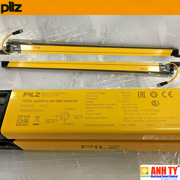 Lưới sáng an toàn Pilz PSEN opII3H-s-30-090 | 632025Giá tốt nhất xem...0909186879 Email
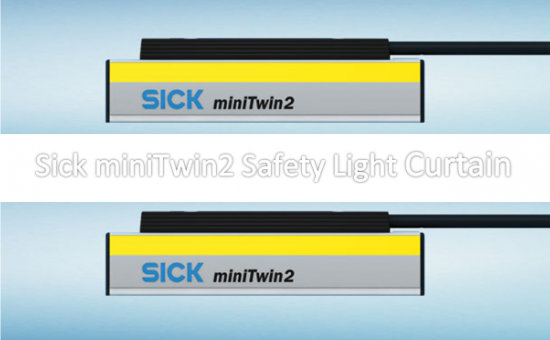
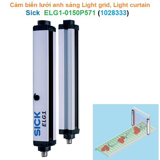 Cảm biến lưới anh sáng Light grid Light curtain - Sick - ELG1-0150P571 (P/N:Giá tốt nhất xem...0909186879 Email
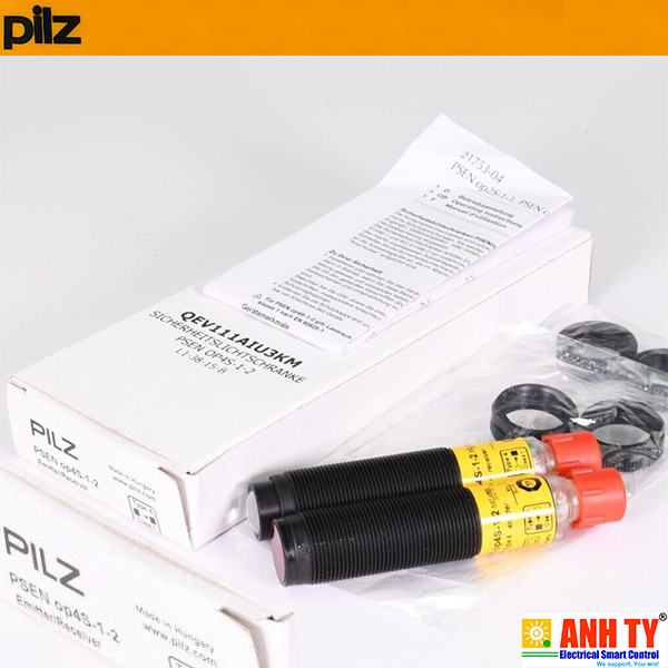 Chùm tia an toàn 40m 0.33ms Type4 PL-e 68.2mm 4-pin M12 Pilz PSEN op4S-1-2 |Giá tốt nhất xem...0909186879 Email
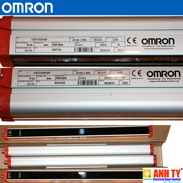 Omron F3ET2-018-450 | Light curtain sensor -Cảm biến rèm ánh sáng Mean-450mmGiá tốt nhất xem...0909186879 Email
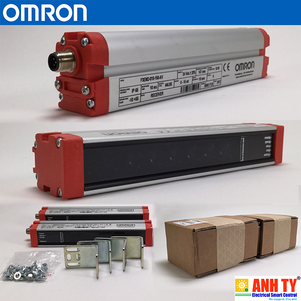 Omron F3EM2-018-150-AV | Light curtain sensor Receiver -Cảm biến rèm ánh sángGiá tốt nhất xem...0909186879 EmailCảm biến lưới anh sáng Light grid Light curtain - Sick - ELG1-0150P571 (P/N: 1028333)Giá tốt nhất Xem...0909186879 EmailOmron F3EM2-018-150-AV | Light curtain sensor Receiver -Cảm biến rèm ánh sáng Mean-150mm Pitc-18mm Sens-15m Chan-8 24VDC 0-10V M12 5-pinGiá tốt nhất Xem...0909186879 EmailOmron F3ET2-018-450 | Light curtain sensor -Cảm biến rèm ánh sáng Mean-450mm Pitc-18mm Sens-15m Chan-24 24VDC PNP/NPN M12 5-pinGiá tốt nhất Xem...0909186879 EmailLưới sáng an toàn Pilz PSEN opII3H-s-30-090 | 632025Giá tốt nhất Xem...0909186879 EmailCảm biến Rèm ánh sáng 8-bea H185mm PNP Omron F3SJ-B0625P25Giá tốt nhất Xem...0909186879 EmailChùm tia an toàn 40m 0.33ms Type4 PL-e 68.2mm 4-pin M12 Pilz PSEN op4S-1-2 | 630382Giá tốt nhất Xem...0909186879 Email


 813
813