


 dienelectrics@gmail.com
 0909186879 dienelectrics@gmail.com


|
Interface |
Benefits |
|
DRIVE-CLiQ |
- Very high data transfer rates possible - Advantages in time-critical applications - Simple and quick automatic configuration using electronic rating plates - Fast and easy diagnostics with a single tool - One interface for connecting drives as well as indirect and direct measurement systems to the CNC. |
|
SSI |
- Advantages in time-critical applications |
|
EnDat 2.1 |
- High data transfer rate, bidirectional - Advantages in time-critical applications - Incremental track with 1 Vpp - Connection via SINAMICS Sensor Modules SMC/SME |
|
PROFIBUS DP-V2 |
- Parameterizable built-on encoder - Reduced wiring overhead in plants with a large number of encoders - Isochronous operation and direct data exchange |
|
PROFINET IO |
- Parameterizable built-on encoder - Reduced wiring overhead in plants with a large number of encoders - Supports conformity class C (IRT communication), B, A (RT communication) - IRT (isochronous mode) - 2 ports - Media redundancy with MRPD, MRP |
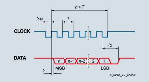
Data transfer for absolute encoders with SSI interface
n = data word length (13 bits for single-turn and 25 bits for multi-turn)
T = 1 ... 10 µs
t cal = ≤ 5 µs
t 1 = ≤ 0.4 µs (without cable)
t 2 = 17 ... 20 µs
|
Article No. |
|
6FX2001-5.D..-1AA0 |
6FX2001-5.S.. |
6FX2001-5.E.. |
|
Product name |
|
Motion Control encoder |
Motion Control encoder |
Motion Control encoder |
|
Product designation |
|
Absolute encoder |
Absolute encoder |
Absolute encoder |
|
Operating voltage DC |
V |
24 |
4.75 ... 30 |
3.6 ... 14 |
|
Current consumption, approx. |
|
|
|
|
| Single-turn |
mA |
37 |
90 |
90 |
| Multi-turn |
mA |
43 |
120 |
120 |
|
Interface |
|
DRIVE-CLiQ |
SSI |
EnDat 2.1 |
|
Clock input |
|
– |
Differential cable receiver acc. to EIA standard RS485 |
Differential cable receiver acc. to EIA standard RS485 |
|
Data output |
|
DRIVE-CLiQ |
Differential cable driver acc. to EIA standard RS485 |
Differential cable driver acc. to EIA standard RS485 |
|
Short-circuit strength |
|
Yes |
Yes |
Yes |
|
Transfer rate |
Mbit/s |
100 |
– |
– |
|
Transfer rate |
kHz |
– |
100 ... 1000 |
100 ... 2000 |
|
Maximum speed |
|
|
|
|
| Electrical |
rpm |
14000 |
– |
– |
| At ± 1 bit accuracy |
rpm |
– |
5000 |
5000 |
| At ± 12 bit accuracy |
rpm |
12000 |
– |
– |
| At ± 100 bit accuracy |
rpm |
– |
12000 |
12000 |
| Mechanical |
|
|
|
|
| Single-turn |
rpm |
15000 |
15000 |
15000 |
| Multi-turn |
rpm |
12000 |
12000 |
12000 |
|
Cable length to downstream electronics, maximum1) |
m (ft) |
100 (328) |
– |
– |
| Up to 300 kHz cycle |
m (ft) |
– |
100 (328) |
150 (492) |
| Up to 1 MHz cycle |
m (ft) |
– |
50 (164) |
50 (164) |
| Up to 2 MHz cycle |
m (ft) |
– |
– |
10 (32.8) |
|
Connection |
|
Radial flange outlet M12 |
Axial/radial flange outlet M23 |
Axial/radial flange outlet M23 |
|
Resolution |
|
|
|
|
| Single-turn |
bit |
24 |
13 |
13 |
| Multi-turn |
bit |
36 |
25 |
25 |
|
Frame |
|
|
|
|
| Single-turn |
bit |
– |
13 |
According to EnDat specification |
| Multi-turn |
bit |
– |
25 |
According to EnDat specification |
|
Incremental track |
S/R |
2048, 1 Vpp |
– |
512, 1 Vpp |
|
Code type |
|
|
|
|
| Transfer |
|
DRIVE-CLiQ |
Gray, fir tree format |
Dual |
|
Parameterization capability |
|
|
|
|
| Preset |
|
– |
Set to zero |
– |
| Counting direction |
|
– |
Yes |
– |
|
Accuracy |
arcsec |
± 20 |
± 60 |
± 60 |
|
Starting torque at 20 °C (68 °F) |
Nm (lbf‑ft) |
≤ 0.01 (0.01) |
≤ 0.01 (0.01) |
≤ 0.01 (0.01) |
|
Solid shaft loading capacity |
|
|
|
|
| n ≤ 6000 rpm |
|
|
|
|
| Axial |
N (lbf) |
40 (8.99) |
40 (8.99) |
40 (8.99) |
| Radial at shaft extension |
N (lbf) |
60 (13.5) |
60 (13.5) |
60 (13.5) |
| n > 6000 rpm |
|
|
|
|
| Axial |
N (lbf) |
10 (2.25) |
10 (2.25) |
10 (2.25) |
| Radial at shaft extension |
N (lbf) |
20 (4.50) |
20 (4.50) |
20 (4.50) |
|
Shaft diameter |
|
|
|
|
| Synchro flange Solid shaft |
mm (in) |
6 (0.24) |
6 (0.24) |
6 (0.24) |
| Clamp flange Solid shaft |
mm (in) |
10 (0.39) |
10 (0.39) |
10 (0.39) |
| Torque arm Hollow shaft |
mm (in) |
10 (0.39) or 12 (0.47) |
– |
– |
|
Shaft length |
|
|
|
|
| Synchro flange |
mm (in) |
10 (0.39) |
10 (0.39) |
10 (0.39) |
| Clamp flange |
mm (in) |
20 (0.79) |
20 (0.79) |
20 (0.79) |
|
Angular acceleration, maximum |
rad/s2 |
105 |
105 |
105 |
|
Moment of inertia of rotor |
|
|
|
|
| Solid shaft |
kgm2 (lbf-in-s2) |
≤ 2.9 × 10⁻⁶ (2.57 × 10⁻⁵) |
≤ 2.9 × 10⁻⁶ (2.57 × 10⁻⁵) |
≤ 2.9 × 10⁻⁶ (2.57 × 10⁻⁵) |
| Hollow shaft |
kgm2 (lbf-in-s2) |
4.6 × 10⁻⁶ (4.07 × 10⁻⁵) |
– |
– |
|
Vibration (55 ... 2000 Hz) according to EN 60068‑2‑6 |
|
|
|
|
| Solid shaft |
m/s2 (ft/s2) |
≤ 300 (984) |
≤ 300 (984) |
≤ 300 (984) |
| Hollow shaft |
m/s2 (ft/s2) |
≤ 150 (492) |
– |
– |
|
Shock according to EN 60068‑2‑27 |
|
|
|
|
| 6 ms |
|
|
|
|
| Solid shaft |
m/s2 (ft/s2) |
≤ 2000 (6562) |
≤ 2000 (6562) |
≤ 2000 (6562) |
| Hollow shaft |
m/s2 (ft/s2) |
≤ 1000 (3281) |
– |
– |
|
Degree of protection |
|
|
|
|
| At housing |
|
IP67 |
IP67 |
IP67 |
| At shaft input |
|
IP64 |
IP64 |
IP64 |
|
Ambient temperature, during |
|
|
|
|
| Operation |
°C (°F) |
-30 ... +100 (-22 ... +212) |
-40 ... +100 (-40 ... +212) |
-40 ... +100 (-40 ... +212) |
|
Net weight |
|
|
|
|
| Single-turn |
kg (lb) |
0.35 (0.77) |
0.35 (0.77) |
0.35 (0.77) |
| Multi-turn |
kg (lb) |
0.35 (0.77) |
0.35 (0.77) |
0.35 (0.77) |
|
EMC |
|
EMC Directive 2014/30/EC and regulations of EMC directives (applicable basic standards) |
EMC Directive 2014/30/EC and regulations of EMC directives (applicable basic standards) |
EMC Directive 2014/30/EC and regulations of EMC directives (applicable basic standards) |
|
Certificate of suitability |
|
CE, CSA, UL |
CE, CSA, UL |
CE, CSA, UL |
S/R = signals/revolution
|
Article No. |
|
6FX2001-5.P.. |
6FX2001-5.N.. |
|
Product name |
|
Motion Control encoder |
Motion Control encoder |
|
Product designation |
|
Absolute encoder with PROFIBUS DP |
Absolute encoder with PROFINET IO |
|
Operating voltage DC |
V |
10 ... 30 |
10 ... 30 |
|
Current consumption, approx. |
|
|
|
| Single-turn |
mA |
300 ... 100 (2.5 W) |
400 ... 130 (4 W) |
| Multi-turn |
mA |
300 ... 100 (2.5 W) |
400 ... 130 (4 W) |
|
Interface |
|
PROFIBUS DP-V2 |
PROFINET IO with RT/IRT |
|
Clock input |
|
Differential cable receiver acc. to EIA standard RS485 |
2 ports IRT |
|
Data output |
|
Differential cable driver acc. to EIA standard RS485 |
2 ports IRT |
|
Short-circuit strength |
|
Yes |
Yes |
|
Transfer rate |
Mbit/s |
12 |
100 |
|
LED for diagnostics |
|
Green/red |
Green/red/yellow/orange |
|
Maximum speed |
|
|
|
| Electrical |
|
|
|
| At ± 1 bit accuracy |
rpm |
5000 |
5000 |
| Mechanical |
|
|
|
| Single-turn |
rpm |
12000 |
12000 |
| Multi-turn |
rpm |
6000 |
6000 |
|
Cable length to downstream electronics, maximum1) |
|
|
|
| Up to 93.75 kbit/s |
m (ft) |
1200 (3937) |
– |
| Up to 1.5 Mbit/s |
m (ft) |
200 (656) |
– |
| Up to 12 Mbit/s |
m (ft) |
100 (328) |
100 (328) |
|
Number of nodes |
|
99 |
– |
|
Connection |
|
Terminal block with address selector switch and bus terminating resistor in removable cover with radial cable glands (3 units) |
2 × M12 connector, 4-pole for PROFINET ports |
| Cable diameter |
mm (in) |
6.5 ... 9 (0.26 ... 0.35) |
– |
|
Resolution |
|
|
|
| Single-turn |
bit |
13 |
13 with V 4.1, 16 with V 4.2 |
| Multi-turn |
bit |
27 |
27 with V 4.1, 30 with V 4.2 |
|
Frame |
|
According to PNO encoder profile V 4.1 |
According to PNO encoder profile V 4.1 and V 4.2 |
|
Code type |
|
|
|
| Sampling |
|
Gray |
Gray |
| Transfer |
|
Binary, PROFIBUS |
Binary, PROFINET |
|
Bus load, approx. |
|
|
|
| At 12 Mbit/s per encoder |
µs |
20 |
– |
|
Cycle time |
ms |
1 |
1 ... 100 |
|
Parameterization capability |
|
|
|
| Resolution per revolution |
|
1 ... 8192 |
1 ... 8192 |
| Total resolution |
|
1 ... 134217728 |
1 ... 134217728 |
| Preset |
|
Yes |
Yes |
| Counting direction |
|
Yes |
Yes |
| Velocity signal |
|
Yes |
Yes |
| Limit switches |
|
Yes, 2 units |
No |
| Isochronous mode |
|
Yes |
Yes |
| Direct data exchange |
|
Yes |
No |
|
Online parameterization |
|
Yes |
Yes |
|
PNO certificate |
|
Yes |
Yes |
|
Supported profiles |
|
PNO encoder profile V 4.1 |
PNO encoder profile V 4.1 and V 4.2 |
|
Accuracy with 8192 steps |
arcsec |
± 79 (± ½ LSB) |
± 79 (± ½ LSB) |
|
Friction torque at 20 °C (68 °F) |
Nm (lbf‑ft) |
≤ 0.03 (0.02) |
≤ 0.03 (0.02) |
|
Starting torque at 20 °C (68 °F) |
Nm (lbf‑ft) |
≤ 0.03 (0.02) |
≤ 0.03 (0.02) |
|
Shaft loading capacity |
|
|
|
| n ≤ 6000 rpm |
|
|
|
| Axial |
N (lbf) |
40 (8.99) |
40 (8.99) |
| Radial at shaft extension |
N (lbf) |
110 (24.7) |
110 (24.7) |
| n > 6000 rpm |
|
|
|
| Axial |
N (lbf) |
10 (2.25) |
10 (2.25) |
| Radial at shaft extension |
N (lbf) |
20 (4.50) |
20 (4.50) |
|
Shaft diameter |
|
|
|
| Synchro flange Solid shaft |
mm (in) |
6 (0.24) |
6 (0.24) |
| Clamp flange Solid shaft |
mm (in) |
10 (0.39) |
10 (0.39) |
| Torque arm Hollow shaft2) |
mm (in) |
5 ... 15 (0.20 ... 0.59) |
5 ... 15 (0.20 ... 0.59) |
|
Shaft length |
|
|
|
| Synchro flange |
mm (in) |
10 (0.39) |
10 (0.39) |
| Clamp flange |
mm (in) |
20 (0.79) |
20 (0.79) |
|
Angular acceleration, maximum |
rad/s2 |
105 |
105 |
|
Moment of inertia of rotor |
|
|
|
| Solid shaft |
kgm2 (lbf-in-s2) |
1.90 × 10⁻⁶ (1.68 × 10⁻⁵) |
1.90 × 10⁻⁶ (1.68 × 10⁻⁵) |
| Hollow shaft |
kgm2 (lbf-in-s2) |
2.80 × 10⁻⁶ (2.47 × 10⁻⁵) |
2.80 × 10⁻⁶ (2.47 × 10⁻⁵) |
|
Vibration (55 ... 2000 Hz) according to EN 60068‑2‑6 |
m/s2 (ft/s2) |
≤ 100 (328) |
≤ 100 (328) |
|
Shock according to EN 60068‑2‑27 |
|
|
|
| 2 ms |
m/s2 (ft/s2) |
≤ 2000 (6562) |
≤ 2000 (6562) |
| 6 ms |
m/s2 (ft/s2) |
≤ 1000 (3281) |
≤ 1000 (3281) |
|
Degree of protection |
|
|
|
| At housing |
|
IP67 |
IP67 |
| At shaft input |
|
IP64 |
IP64 |
|
Ambient temperature, during |
|
|
|
| Operation |
°C (°F) |
-40 ... +85 (-40 ... +185) |
-40 ... +85 (-40 ... +185) |
|
Net weight |
|
|
|
| Single-turn |
kg (lb) |
0.4 (0.88) |
0.4 (0.88) |
| Multi-turn |
kg (lb) |
0.5 (1.1) |
0.5 (1.1) |
|
EMC |
|
EMC Directive 2014/30/EC and regulations of EMC directives (applicable basic standards) |
EMC Directive 2014/30/EC and regulations of EMC directives (applicable basic standards) |
|
Certificate of suitability |
|
CE, CSA, UL |
CE, CSA, UL |
1) Observe the max. permissible cable length of the connected module.
2) Hollow shaft diameter of 12 mm, 10 mm or 8 mm (0.47 in, 0.39 in or 0.31 in) possible using supplied reduction sleeves.


