
| Supply | ||
|---|---|---|
| Rated voltage | 20 ... 30 V DC SELV/PELV | |
| Power consumption | < 5 W | |
| External bus | ||
| Connection | screw terminals for - 0.2 ... 4 mm2 (rigid wire) - 0.2 ... 2.5 mm2 (flexible wire) |
|
| Interface 1 | Ethernet 10 BASE-T/100 BASE-TX , full galvanic isolation |
|
| Protocol | HART UDP, MODBUS TCP | |
| Cable length | max. 100 m , depending on cables and transfer rate | |
| Connection | UTP, STP or FTP | |
| Interface 2 | RS-485 | |
| Protocol | HART, MODBUS RTU | |
| Daisy-chain capability | supported by duplicated connection terminals | |
| Transfer rate | max. 115 kBit/s | |
| Cable length | max. 1200 m , depending on cables and transfer rate | |
| Bus termination | integrated termination resistor , adjustable via DIP switch and software | |
| Input | ||
| Interface | omnidirectional dipole antenna, removable | |
| Communication | WirelessHART specifications - physical layer: IEEE 802.15.4.2006 - frequency band: 2.4 GHz (ISM band, licence free) - transmission rate: 250 kBit/s - maximum transmit power: +10 dBm (EIRP) - transmission range: outdoor 250 m, indoor 50 m (under reference conditions) - communication standard: WirelessHART acc. to IEC 62591 |
|
| Galvanic isolation | ||
| Interface/power supply | basic insulation according to IEC 61140, rated insulation voltage 50 Veff | |
| Interface/interface | basic insulation according to IEC 61140, rated insulation voltage 50 Veff | |
| Indicators/settings | ||
| Display elements | LED PWR (power supply status), one green LED LED COM (communication status), three yellow LEDs LED FLT (fault signal), one red LED |
|
| Control elements | 2 push buttons: - restore HART configuration - restore communication configuration DIP switches: - baud rate - RS-485 address - RS-485 termination - security mode |
|
| Directive conformity | ||
| Electromagnetic compatibility | ||
| Directive 2014/30/EU | EN 61326-1:2013 | |
| Radio and telecommunication terminal equipment | The usage of 2.4 GHz equipment is bound to local restrictions. Ensure that restrictions allow usage of this product before commisioning. | |
| Directive 2014/53/EU | EN 300328: V2.1.1 EN 301489-17: V1.3.2 |
|
| FCC CFR47 Part 15 B and C | ANSI C63.4-2003 , FCC ID: SJC-M2140 | |
| Conformity | ||
| Degree of protection | IEC 60529 | |
| Shock resistance | EN 60068-2-27 | |
| Vibration resistance | EN 60068-2-6 | |
| Ambient conditions | ||
| Ambient temperature | -20 ... 60 °C (-4 ... 140 °F) | |
| Storage temperature | -40 ... 85 °C (-40 ... 185 °F) | |
| Relative humidity | 5 ... 95 %, noncondensing | |
| Corrosion resistance | acc. to ISA-S71.04-1985, severity level G3 test setup and execution acc. to EN 60068-2-60 |
|
| Mechanical specifications | ||
| Degree of protection | IP66/IP67 | |
| Mass | approx. 1 kg | |
| Dimensions | 258 mm x 114 mm x 84 mm without antenna and cable glands |
|
| Mounting | wall mounting | |
| Data for application in connection with hazardous areas | ||
| EU-type examination certificate | FM 12 ATEX 0061 | |
| Marking |  II 3 G Ex nA nC IIC T4 Gc II 3 G Ex nA nC IIC T4 Gc |
|
| Directive conformity | ||
| Directive 2014/34/EU | EN 60079-0:2012+A11:2013 , EN 60079-15:2010 | |
| International approvals | ||
| FM approval | Coc3042646 | |
| Approved for | NI Class I, Div. 2, GPS A-D NI Class II, Class III, Div. 2, GPS E-G |
|
| IECEx approval | IECEx FMG 12.0002 | |
| Approved for | Ex nA nC IIC T4 Gc , Ex nAc nCc T4 | |
| General information | ||
| Supplementary information | Observe the certificates, declarations of conformity, instruction manuals, and manuals where applicable. For information see www.pepperl-fuchs.com. | |
 Mô-đun Wireless Phoenix Contact FL WLAN 1100 - 2702534 | WLAN802.11a-b- g-nGiá tốt nhất xem...0909186879 Email
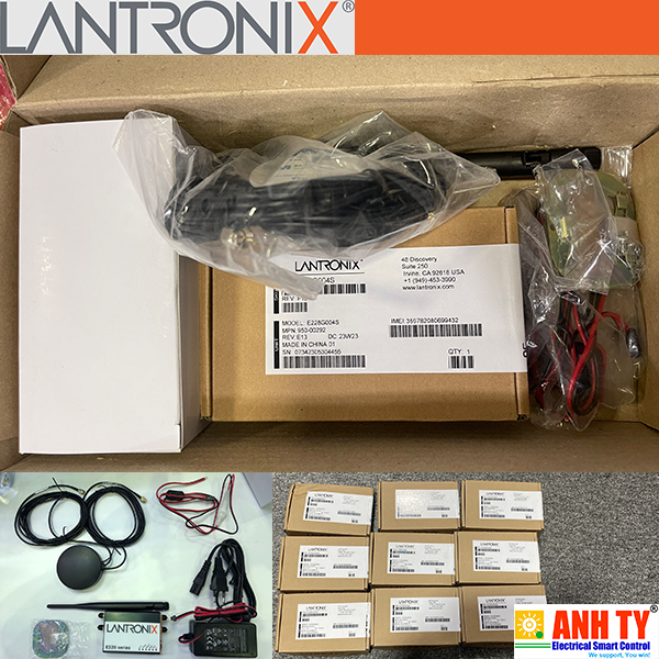
 Bộ định tuyến di động Cellular Router E220 Series Lantronix E228G00xSGiá tốt nhất xem...0909186879 Email
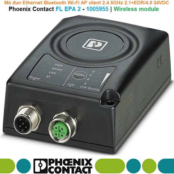
 Phoenix Contact FL EPA 2 - 1005955 | Wireless module -Mô đun Ethernet BluetoothGiá tốt nhất xem...0909186879 Email
 Mô-đun Wireless Phoenix Contact FL WLAN 1100 - 2702534 | WLAN802.11a-b- g-n 2.4GHz 5GHzGiá tốt nhất Xem...0909186879 Email
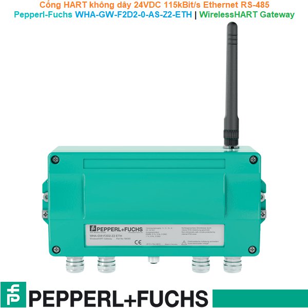
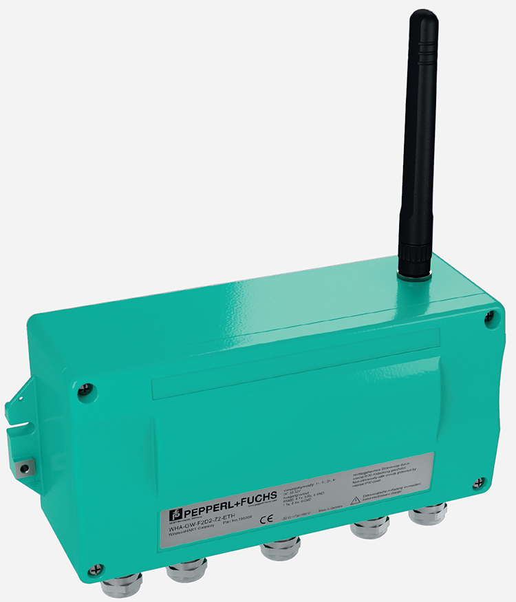
 Pepperl-Fuchs WHA-GW-F2D2-0-AS-Z2-ETH | WirelessHART Gateway -Cổng HART không dây 24VDC 115kBit/s Ethernet HART UDP MODBUS TCP RS-485 HART MODBUS RTUGiá tốt nhất Xem...0909186879 Email
 Phoenix Contact FL EPA 2 - 1005955 | Wireless module -Mô đun Ethernet Bluetooth Wi-Fi AP client 2.4 5GHz 2.1+EDR/4.0 24VDCGiá tốt nhất Xem...0909186879 Email
 Bộ định tuyến di động Cellular Router E220 Series Lantronix E228G00xSGiá tốt nhất Xem...0909186879 Email