Chi tiết thông tin đặc tính sản phẩm Bộ nguồn AC-DC input AC 230V output 12/ 24/ 48VDC 3A 750W - XP Power - GSP750PS12-EF GSP750PS24-EF GSP750PS48-EF
Bộ nguồn AC-DC, series GSP750
- Cấu hình thấp, kích thước nhỏ gọn
- Thích hợp cho các ứng dụng 1U
- Xếp hạng công suất đỉnh 900W trong 100ms
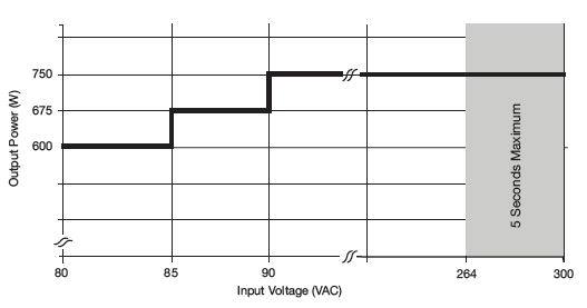
- Đầu vào phổ 80-264 VAC (300 VAC trong 5 giây)
- Phê duyệt an toàn CNTT / Công nghiệp & Y tế (2 x MOPP)
- Ngõ ra chờ 5V / 3A
- Công suất dự phòng 1.0W
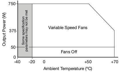
- Điều khiển tốc độ quạt thông minh
- Hoạt động -40 ° C đến + 70 ° C
- PowerFail, Inhibit, Remote Sense & Current Share
The GSP750 offers a full 750 W of output power in a very small mechanical footprint while providing peak power to up to 900 W, a 5 V standby output with 3 A current capability and an input standby power draw of <1.0 W when the inhibit is activated.
Approved for both IT/Industrial and medical applications the series has output versions from 12 V to 48 V. Cooling fans are intelligently controlled to reduce accoustic noise in the system and the GSP750 provides up to 50 W without forced cooling, allowing the fans to be switched off, providing silent running during periods of lower system loading or system standby conditions.
bảo hành 3 năm
Kích thước/ Dimensions
10.0 x 4.0 x 1.65” (254.0 x 101.6 x 41.91 mm)
Models & Ratings
| Putput voltage |
Output current V1 |
Standby supply |
Max output power |
Model number |
| <50 W Load (fans off) |
>50 Load (fans on) |
Nom |
Peak(1) |
| 12 VDC |
62.5 A |
5V/ 1A |
5V/ 1A |
750w |
900w |
GSP750PS12-EF |
| 24VDC |
31.3 A |
5V/ 1A |
5V/ 1A |
750w |
900w |
GSP750PS24-EF |
| 48 VDC |
15.6 A |
5V/ 1A |
5V/ 1A |
750w |
900w |
GSP750PS48-EF |
* Chú ý: (1) Peak power available for 100 ms maximum with a 10% duty cycle. The average power in a period should be equal or less than the nominal power.
Đầu vào/ Input
| Characteristic |
Minimum |
Typical |
maximum |
Units |
Note & Condition |
| Input voltage - Operating |
80 |
115/ 230 |
264 |
VAC |
Derate output power < 90 VAC. See fig 1. |
| Input voltage - Fault condition |
|
|
300 |
VAC |
5 second max |
| Input frequency |
47 |
50/ 60 |
63 |
Hz |
|
| Power factor |
|
> 0.9 |
|
|
230 VAC, 100% load |
| Input current - Full load |
|
8.7/ 4.35 |
|
A |
115/ 230 VAC |
| Inrush current |
|
60 |
|
A |
|
| No load input power |
|
|
1 |
w |
All models, when inhibit axtivated |
| Earth leakage current |
|
80/ 220 |
250 |
µA |
115/ 230 VAC/ 50Hz Type., 264 CAC/ 60Hz Max. |
| Input protection |
F16.0 A/250 V internal fuse in both lines |
Đầu ra/ Output
| Characteristic |
Minimum |
Typical |
Maximum |
Units |
Notes & Conditions |
| Output voltage - V1 |
12 |
|
48 |
VDC |
See Models and Ratings table |
| Initial set accuracy |
|
|
+/- 1 |
% |
50% load, 115/230 VAC |
| Output voltage adjustment |
|
|
+1, -3 |
% |
|
| Minimum load |
0 |
|
|
A |
No minimum load required |
| Start up delay |
|
1.0 |
2.0 |
s |
115/230 VAC full load from input AC turn on |
| Hold up time |
10 |
|
|
ms |
100% load |
| Drift |
|
|
+/-0.5 |
% |
After 20 min warn up |
| Line regulation |
|
|
+/-0.5 |
% |
0-100% load |
| Load regulation |
|
0.2 |
1.0 |
% |
Recovery within 1% in less than 599 µs for a 50-75% and 75-50% load step |
| Transient response |
|
|
4 |
% |
|
| Over/ Undershoot |
|
|
5 |
% |
20 MHz bandwidth |
| Ripple & Noise |
|
0.5 |
1.5 |
% pk-pk |
Vnom DC. Output 1, recycle input to reset |
| Overvoltage protection |
115 |
|
140 |
% |
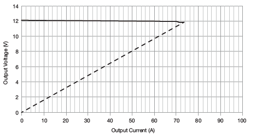
See fig. 2. Trip and Restart |
| Over protection |
110 |
|
150 |
% I nom |
Shutdown & auto recovery |
| Short circuit protection |
|
|
|
|
|
| Temperature coefficient |
|
|
0.05 |
%/oC |
Shutdown & auto recovery |
| Overtemperature protection |
|
|
|
|
|
Input Voltage Derating Curve
Figure 1
Output Overload Characteristic
Figure 2
GSP750PS12 example (others similar).
Thông số chung/ General
| Characteristic |
Minimum |
Typical |
Maximum |
Units |
Notes & Conditions |
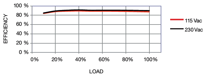
| Efficiency |
|
90 |
|
% |
230 VAC Full load (see fig.3-5) |
Isolation: Input to Output
Input to Ground
Output to Ground |
4000 |
|
|
VAC |
2 x MOPP |
| 1500 |
|
|
VAC |
1 x MOPP |
| 500 |
|
|
VDC |
1 x at 48 VDC |
| Switch frequency |
|
65 |
|
kHz |
PFC Converter |
| 50 |
90 |
200 |
Main converter |
| |
100 |
|
Standby converter |
| Power density |
|
|
11.7 |
W/in3 |
|
| Mean time between failure |
|
186 |
|
KHrs |
MIL- HDBK- 217F, notice 2 +25oC GB |
| Weight |
|
2.97 (1.35) |
|
Ib (kg) |
|
Efficiency Vs Load
Figure 3
12 V Models
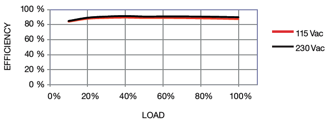
Figure 4
24 V Models
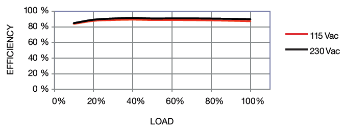
Figure 5
48 V Models
Signals & Controls
| Characteristic |
Notes & Conditions |
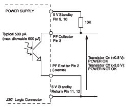
| Power fail (PF) |
Open collector referenced to negative sense, transistor normally on when power is good (see fig. 5); power is considered good when PFC bulk capacitor voltage is normal. PF: Provides >/= 5 ms warning of loss of output from power failure. |
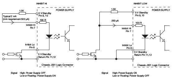
| Inhibit |
Uncommited isolated optocoupler diode, powered diode inhibits both V1 and fan supply (see fig. 6). During inhibit the standby supply and current should be limited to 1 A for thermal reasons. |
| Output good |
LED Indicator |
| Fan speed control |
The fan speed is set to one of 4 states (high, mid, low or off) dependant on the internal power supply ambiennt temperature, input voltage and output load at anhy given time. |
| Standby supply |
5V/ 3A Isolated supply present when AC applied. |
| Remote sense |
Compenstes for 0.5 V total voltage drop. |
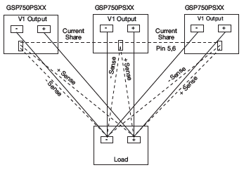
| Current share |
Connedting pins 5 or 6 on one unit to pins 5 or 6 on another like voltage unit will force the current to be shared within 10% between the two outputs. Up to three units can share current. (see gig. 7) |
Power Fail (PF)
Figure 6
Remote On/Off (Inhibit)
Figure 7
Current Share
Figure 8
Environmental
| Characteristic |
Minimum |
Typical |
Maximum |
Units |
Notes & Conditions |
| Operating temperature |
-40 |
|
+70 |
oC |
Start up at -40 oC. See derating curve, fig. 8 |
| Storage temperature |
-40 |
|
+80 |
oC |
|
| Humidity |
5 |
|
95 |
%RH |
Non-condensing |
| operating slyiyufr |
|
|
5000 |
m |
|
| Accoustic fan noise |
|
65.0 |
|
Lw db (A) |
Full speed |
| |
56.0 |
|
Lw db (A) |
Mid speed |
| |
42.0 |
|
Lw db (A) |
Low speed |
| Shock |
|
|
|
|
+/- x 30g shocks in each plane, total 18 shocks. 30g = 11ms (+/- 0.5 msec), half sine. Conforms to EN60068-2-27 & EN60068-2-47 |
| Vibration |
|
|
|
|
Single axis 10 - 50Hz at 2g sweep and endrance at resonance in all 3 planes. Conform to EN60068-2-6 |
Thermal Derating Curve
Figure 9
EMC: Emissions
| Phenomenon |
Standard |
Test level |
Notes & Conditions |
| Conducted |
EN5011/32 |
Class B |
|
| Ratiated |
EN5011/32 |
Class A |
Class B with Wurth 742 712 22(S) on input cable and Wurth 742 715 4(S) on output cable |
| Harmonic fluctuations |
EEN61000-3-3 |
|
|
EMC: Immunity
| Phenomenon |
Standard |
Test level |
Criteria |
Notes & Conditions |
| Low voltage PSU EMC |
EN61204-3 |
High severity level |
as below |
|
| Harmonic current |
EN61000-3-2 |
Class A |
|
All models |
| Class C |
|
>50 W |
| Radiated |
EN61000-4-3 |
3 |
A |
|
| EFT |
EN61000-4-4 |
3 |
A |
|
| Surges |
EN61000-4-5 |
Installation class 3 |
A |
|
| |
| Conducted |
EN61000-4-6 |
3 |
A |
|
| Dips and Interrruptions |
EN55024
(100 VAC) |
Dip >95% (0 VAC), 8.3ms |
A |
Derate output power 70% for criteria A |
| Dip >30% (70 VAC), 416ms |
A |
Derate output power to 50% |
| Dip >95% (0 VAC), 416ms |
B |
|
EN55024
(240 VAC) |
Dip >95% (0 VAC), 10.0ms |
A |
|
| Dip >30% (168 VAC), 500ms |
A |
|
| Dip >95% (0 VAC), 5000ms |
B |
Derate output power to 70% for criteria A |
EN60601-1-2
(100 VAC) |
Dip >95% (0 VAC), 10.0ms |
A |
|
| Dip >95% (0 VAC), 20.0ms |
B |
|
| Dip >60% (40 VAC), 100ms |
A |
|
| Dip >30% (70 VAC), 500ms |
A |
|
| Dip >95% (0 VAC), 5000ms |
B |
|
EN60601-1-2
(240 VAC) |
Dip >95% (0 VAC), 10.0ms |
A |
|
| Dip >95% (0 VAC), 20.0ms |
B |
|
| Dip >60% (96 VAC), 100ms |
A |
|
| Dip >30% (168 VAC), 500ms |
A |
|
| Dip >95% (0 VAC), 5000ms |
B |
|
Safety Approvals
| Safety agency |
Safety standard |
Notes & Conditions |
| CB report |
IEC60950-1: 2005 Ed 2 |
Information technology |
| |
IEEC60601-1 Ed 3 Including risk management |
Medical |
| UL |
UL60950-1 (2007), CSA 22.2 No.6095-1-1: 08 |
Information technology |
| |
ANSI/AAMI ES60601-1: 2005 & CSA C22.2, No.60601-1: 08 |
Medical |
| TUV |
EN60905-1: 2006 |
Information technology |
| |
EEN60601-1/À: 2006 |
Medical |
| CE |
LVD & RoHS |
|
| Equipment protection class |
Class I |
See safety agency conditions of acceptibility for details |
| Means of Protection |
Category |
| Primary to secondary |
2 x MOPP (Means of patient protection) |
IEC60601-1 Ed 3 |
| Primary to earth |
1 x MOPP (Means of patient protection) |
| Secondary to earth |
1 x MOPP at 48 VDC |
Mechanical Details
(See on Datasheet below)
| Logic Connector(3) |
| Pin |
Fucction |
| 1 |
+Sense |
| 2 |
-Siense |
| 3 |
Power fail |
| 4 |
No connection |
| 5 |
Current share |
| 6 |
Current share |
| 7 |
+Inhibit |
| 8 |
-Inhibit |
| 9 |
+5V standby |
| 10 |
+5V standby |
| 11 |
5V standby return |
| 12 |
5V standby return |
| 13 |
No connection |
| 14 |
No connection |


 dienelectrics@gmail.com
 0909186879
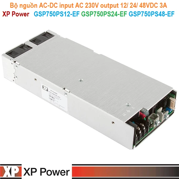
 2,963
2,963


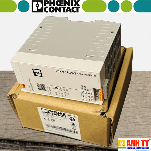 Bộ nguồn 1AC 2x15VDC 2A Phoenix Contact QUINT4-PS/1AC/2X15DC/2/PT - 2904596Giá tốt nhất xem...0909186879 Email
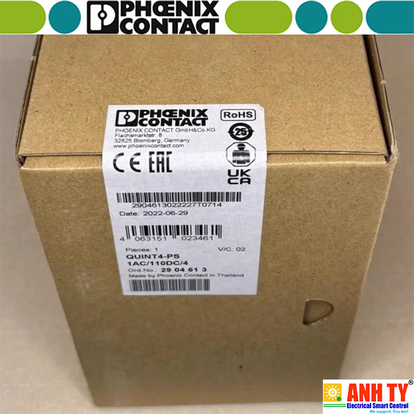 Bộ nguồn 1AC 110VDC 4A Phoenix Contact QUINT4-PS/1AC/110DC/4 - 2904613Giá tốt nhất xem...0909186879 Email
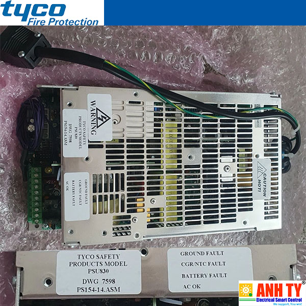 Bộ nguồn 100-264VAC 27.3VDC 2A Tyco PSU830 | 557.202.210Giá tốt nhất xem...0909186879 Email
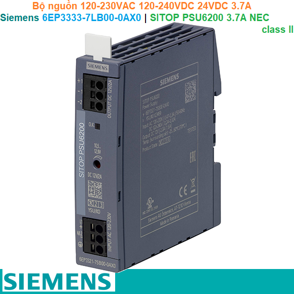 Siemens 6EP3333-7LB00-0AX0 | SITOP PSU6200 3.7 A NEC class II -Bộ nguồnGiá tốt nhất xem...0909186879 Email
 Bộ nguồn Phoenix Contact TRIO-PS/1AC/24DC/20 - 2866381 | 1AC 24VDC 20AGiá tốt nhất Xem...0909186879 Email
 Bộ nguồn Phoenix Contact TRIO-PS/1AC/24DC/10 - 2866323 | 1AC 24VDC 10A Giá tốt nhất Xem...0909186879 Email
 Bộ nguồn Phoenix Contact TRIO-PS/1AC/24DC/ 5 - 2866310 | 1P 24VDC 5AGiá tốt nhất Xem...0909186879 Email
 Bộ nguồn 24vDC 10A 1AC 120/230V - Siemens - SITOP PSU100S 24 V/10 A - 6EP1334-2BA20Giá tốt nhất Xem...0909186879 Email
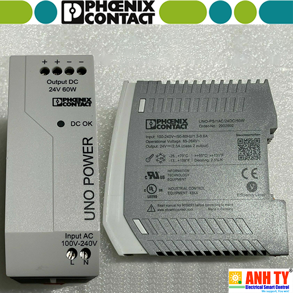 Bộ nguồn 24vDC-60W Phoenix Contact Power supply unit - UNO-PS/1AC/24DC/ 60W - 2902992Giá tốt nhất Xem...0909186879 Email
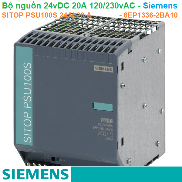 Bộ nguồn Siemens 6EP1336-2BA10 | SITOP PSU100S 20A | 120/230VAC 24VDC 20AGiá tốt nhất Xem...0909186879 Email
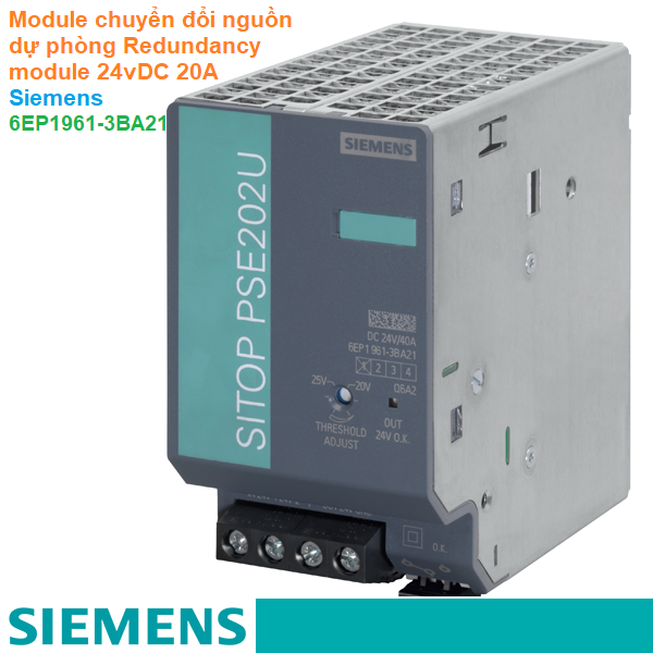 Module chuyển đổi nguồn dự phòng Redundancy module 24vDC 20A - Siemens - 6EP1961-3BA21Giá tốt nhất Xem...0909186879 Email
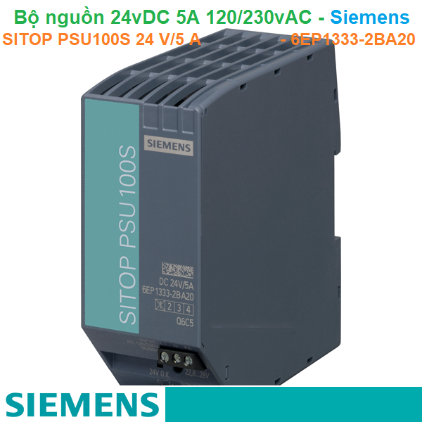 Bộ nguồn Siemens 6EP1333-2BA20 | SITOP PSU100S 24 V/5 A | 120/230VAC 24VDC 5AGiá tốt nhất Xem...0909186879 Email
 Bộ nguồn 24vDC-100W Phoenix Contact Power supply unit - UNO-PS/1AC/24DC/100W - 2902993Giá tốt nhất Xem...0909186879 Email


