| General information |
| Product type designation |
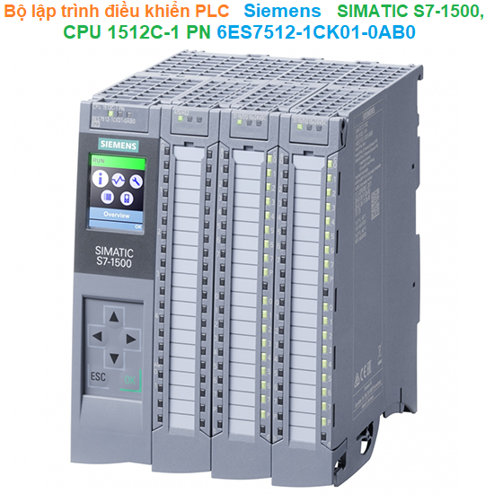
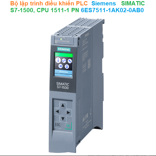
CPU 1511C-1 PN |
| HW functional status |
FS01 |
| Firmware version |
V2.6 |
| Product function |
| -I&M data |
Yes; I&M0 to I&M3 |
| Engineering with |
| -STEP 7 TIA Portal configurable/integrated as of version |
V15.1 (FW V2.6) / V15 (FW V2.5) or higher; with older TIA Portal versions configurable as 6ES7511-1CK00-0AB0 |
| Configuration control |
| via dataset |
Yes |
| Display |
| Screen diagonal [cm] |
3.45 cm |
| Control elements |
| Number of keys |
8 |
| Mode buttons |
2 |
| Supply voltage |
| Type of supply voltage |
24 V DC |
| permissible range, lower limit (DC) |
19.2 V; 20.4 V DC, for supplying the digital inputs/outputs |
| permissible range, upper limit (DC) |
28.8 V |
| Reverse polarity protection |
Yes |
| Mains buffering |
| -Mains/voltage failure stored energy time |
5 ms; Refers to the power supply on the CPU section |
| -Repeat rate, min. |
1/s |
| Input current |
| Current consumption (rated value) |
0.8 A; Without load; 9.8 A: CPU + load |
| Current consumption, max. |
1 A; Without load; 10 A: CPU + load |
| Inrush current, max. |
1.9 A; Rated value |
| I²t |
0.34 A²·s |
| Digital inputs |
| -from load voltage L+ (without load), max. |
20 mA; per group |
| Digital outputs |
| -from load voltage L+, max. |
30 mA; Per group, without load |
| Output voltage |
| Rated value (DC) |
24 V |
| Encoder supply |
| Number of outputs |
1; One common 24 V encoder supply |
| 24 V encoder supply |
| -24 V |
Yes; L+ (-0.8 V) |
| -Short-circuit protection |
Yes |
| -Output current, max. |
1 A |
| Power |
| Infeed power to the backplane bus |
10 W |
| Power consumption from the backplane bus (balanced) |
8.5 W |
| Power loss |
| Power loss, typ. |
11.8 W |
| Memory |
| Number of slots for SIMATIC memory card |
1 |
| SIMATIC memory card required |
Yes |
| Work memory |
| -integrated (for program) |
175 kbyte |
| -integrated (for data) |
1 Mbyte |
| Load memory |
| -Plug-in (SIMATIC Memory Card), max. |
32 Gbyte |
| Backup |
| -maintenance-free |
Yes |
| CPU processing times |
| for bit operations, typ. |
60 ns |
| for word operations, typ. |
72 ns |
| for fixed point arithmetic, typ. |
96 ns |
| for floating point arithmetic, typ. |
384 ns |
| CPU-blocks |
| Number of elements (total) |
2 000; Blocks (OB, FB, FC, DB) and UDTs |
| DB |
| -Number range |
1 ... 60 999; subdivided into: number range that can be used by the user: 1 ... 59 999, and number range of DBs created via SFC 86: 60 000 ... 60 999 |
| -Size, max. |
1 Mbyte; For DBs with absolute addressing, the max. size is 64 KB |
| FB |
| -Number range |
0 ... 65 535 |
| -Size, max. |
175 kbyte |
| FC |
| -Number range |
0 ... 65 535 |
| - Size, max. |
175 kbyte |
| OB |
| - Size, max. |
175 kbyte |
| - Number of free cycle OBs |
100 |
| - Number of time alarm OBs |
20 |
| - Number of delay alarm OBs |
20 |
| - Number of cyclic interrupt OBs |
20; With minimum OB 3x cycle of 500 µs |
| - Number of process alarm OBs |
50 |
| - Number of DPV1 alarm OBs |
3 |
| - Number of isochronous mode OBs |
1 |
| - Number of technology synchronous alarm OBs |
2 |
| - Number of startup OBs |
100 |
| - Number of asynchronous error OBs |
4 |
| - Number of synchronous error OBs |
2 |
| - Number of diagnostic alarm OBs |
1 |
| Nesting depth |
| - per priority class |
24 |
| Counters, timers and their retentivity |
| S7 counter |
| - Number |
2 048 |
| Retentivity |
| - adjustable |
Yes |
| IEC counter |
| - Number |
Any (only limited by the main memory) |
| Retentivity |
| - adjustable |
Yes |
| S7 times |
| - Number |
2 048 |
| Retentivity |
| - adjustable |
Yes |
| IEC timer |
| - Number |
Any (only limited by the main memory) |
| Retentivity |
| - adjustable |
Yes |
| Data areas and their retentivity |
| Retentive data area (incl. timers, counters, flags), max. |
128 kbyte; In total; available retentive memory for bit memories, timers, counters, DBs, and technology data (axes): 88 KB |
| Extended retentive data area (incl. timers, counters, flags), max. |
1 Mbyte; When using PS 6 0W 24/48/60 V DC HF |
| Flag |
| - Number, max. |
16 kbyte |
| - Number of clock memories |
8; 8 clock memory bit, grouped into one clock memory byte |
| Data blocks |
| - Retentivity adjustable |
Yes |
| - Retentivity preset |
No |
| Local data |
| - per priority class, max. |
64 kbyte; max. 16 KB per block |
| Address area |
| Number of IO modules |
1 024; max. number of modules / submodules |
| I/O address area |
| - Inputs |
32 kbyte; All inputs are in the process image |
| - Outputs |
32 kbyte; All outputs are in the process image |
| per integrated IO subsystem |
| - Inputs (volume) |
8 kbyte |
| - Outputs (volume) |
8 kbyte |
| per CM/CP |
| - Inputs (volume) |
8 kbyte |
| - Outputs (volume) |
8 kbyte |
| Subprocess images |
| - Number of subprocess images, max. |
32 |
| Hardware configuration |
| Number of distributed IO systems |
32; A distributed I/O system is characterized not only by the integration of distributed I/O via PROFINET or PROFIBUS communication modules, but also by the connection of I/O via AS-i master modules or links (e.g. IE/PB-Link) |
| Number of DP masters |
| - Via CM |
4; A maximum of 4 CMs/CPs (PROFIBUS, PROFINET, Ethernet) can be inserted in total |
| Number of IO Controllers |
| - integrated |
1 |
| - Via CM |
4; A maximum of 4 CMs/CPs (PROFIBUS, PROFINET, Ethernet) can be inserted in total |
| Rack |
| - Modules per rack, max. |
32; CPU + 31 modules |
| - Number of lines, max. |
1 |
| PtP CM |
| - Number of PtP CMs |
the number of connectable PtP CMs is only limited by the number of available slots |
| Time of day |
| Clock |
| - Type |
Hardware clock |
| - Backup time |
6 wk; At 40 °C ambient temperature, typically |
| - Deviation per day, max. |
10 s; Typ.: 2 s |
| Operating hours counter |
| - Number |
16 |
| Clock synchronization |
| - supported |
Yes |
| - in AS, master |
Yes |
| - in AS, slave |
Yes |
| - on Ethernet via NTP |
Yes |
| Digital inputs |
| integrated channels (DI) |
16 |
| Digital inputs, parameterizable |
Yes |
| Source/sink input |
P-reading |
| Input characteristic curve in accordance with IEC 61131, type 3 |
Yes |
| Digital input functions, parameterizable |
| - Gate start/stop |
Yes |
| - Capture |
Yes |
| - Synchronization |
Yes |
| Input voltage |
| - Type of input voltage |
DC |
| - Rated value (DC) |
24 V |
| - for signal "0" |
-3 to +5V |
| - for signal "1" |
+11 to +30V |
| Input current |
| - for signal "1", typ. |
2.5 mA |
| Input delay (for rated value of input voltage) |
| for standard inputs |
| — parameterizable |
Yes; none / 0.05 / 0.1 / 0.4 / 1.6 / 3.2 / 12.8 / 20 ms |
| — at "0" to "1", min. |
4 µs; for parameterization "none" |
| — at "0" to "1", max. |
20 ms |
| — at "1" to "0", min. |
4 µs; for parameterization "none" |
| — at "1" to "0", max. |
20 ms |
| for interrupt inputs |
| — parameterizable |
Yes; Same as for standard inputs |
| for technological functions |
| — parameterizable |
Yes; Same as for standard inputs |
| Cable length |
| - shielded, max. |
1 000 m; 600 m for technological functions; depending on input frequency, encoder and cable quality; max. 50 m at 100 kHz |
| - unshielded, max. |
600 m; For technological functions: No |
| Digital outputs |
| Type of digital output |
Transistor |
| integrated channels (DO) |
16 |
| Current-sourcing |
Yes; Push-pull output |
| Short-circuit protection |
Yes; electronic/thermal |
| - Response threshold, typ. |
1.6 A with standard output, 0.5 A with high-speed output; see manual for details |
| Limitation of inductive shutdown voltage to |
-0.8 V |
| Controlling a digital input |
Yes |
| Accuracy of pulse duration |
Up to ±100 ppm ±2 μs at high-speed output; see manual for details |
| minimum pulse duration |
2 µs; With High Speed output |
| Digital output functions, parameterizable |
| - Switching tripped by comparison values |
Yes; As output signal of a high-speed counter |
| - PWM output |
Yes |
| - Number, max. |
4 |
| - Cycle duration, parameterizable |
Yes |
| - ON period, min. |
0 % |
| - ON period, max. |
100 % |
| - Resolution of the duty cycle |
0.0036 %; For S7 analog format, min. 40 ns |
| - Frequency output |
Yes |
| - Pulse train |
Yes; also for pulse/direction interface |
| Switching capacity of the outputs |
| - with resistive load, max. |
0.5 A; 0.1 A with high-speed output, i.e. when using a high-speed output; see manual for details |
| - on lamp load, max. |
5 W; 1 W with high-speed output, i.e. when using a high-speed output; see manual for details |
| Load resistance range |
| - lower limit |
48 Ω; 240 ohms with high-speed output, i.e. when using a high-speed output; see manual for details |
| - upper limit |
12 kΩ |
| Output voltage |
| - Type of output voltage |
DC |
| - for signal "0", max. |
1 V; With high-speed output, i.e. when using a high-speed output; see manual for details |
| - for signal "1", min. |
23.2 V; L+ (-0.8 V) |
| Output current |
| - for signal "1" rated value |
0.5 A; 0.1 A with high-speed output, i.e. when using a high-speed output, observe derating; see manual for details |
| - for signal "1" permissible range, min. |
2 mA |
| - for signal "1" permissible range, max. |
0.6 A; 0.12 A with high-speed output, i.e. when using a high-speed output, observe derating; see manual for details |
| - for signal "0" residual current, max. |
0.5 mA |
| Output delay with resistive load |
| - "0" to "1", max. |
200 µs |
| - "1" to "0", max. |
500 µs; Load-dependent |
| for technological functions |
| - "0" to "1", max. |
5 µs; Depending on the output used, see additional description in manual |
| - "1" to "0", max. |
5 µs; Depending on the output used, see additional description in manual |
| Parallel switching of two outputs |
| - for logic links |
Yes; For technological functions: No |
| - for uprating |
No |
| - for redundant control of a load |
Yes; For technological functions: No |
| Switching frequency |
| - with resistive load, max. |
100 kHz; For high-speed output, 100 Hz for standard output |
| - with inductive load, max. |
0.5 Hz; Acc. to IEC 60947-5-1, DC-13; observe derating curve |
| - on lamp load, max. |
10 Hz |
| Total current of the outputs |
| - Current per channel, max. |
0.5 A; see additional description in the manual |
| - Current per group, max. |
8 A; see additional description in the manual |
| - Current per power supply, max. |
4 A; 2 power supplies for each group, current per power supply max. 4 A, see additional description in manual |
| for technological functions |
| - Current per channel, max. |
0.5 A; see additional description in the manual |
| Relay outputs |
| - Number of relay outputs |
0 |
| Cable length |
| - shielded, max. |
1 000 m; 600 m for technological functions; depending on output frequency, load, and cable quality; max. 50 m at 100 kHz |
| - unshielded, max. |
600 m; For technological functions: No |
| Analog inputs |
| Number of analog inputs |
5; 4x for U/I, 1x for R/RTD |
| - For current measurement |
4; max. |
| - For voltage measurement |
4; max. |
| - For resistance/resistance thermometer measurement |
1 |
| permissible input voltage for voltage input (destruction limit), max. |
28.8 V |
| permissible input current for current input (destruction limit), max. |
40 mA |
| Cycle time (all channels), min. |
1 ms; Dependent on the parameterized interference frequency suppression; for details, see conversion procedure in manual |
| Technical unit for temperature measurement adjustable |
Yes; °C/°F/K |
| Input ranges (rated values), voltages |
| - 0 to +10 V |
Yes; Physical measuring range: ± 10 V |
| - Input resistance (0 to 10 V) |
100 kΩ |
| - 1 V to 5 V |
Yes; Physical measuring range: ± 10 V |
| - Input resistance (1 V to 5 V) |
100 kΩ |
| - -10 V to +10 V |
Yes |
| - Input resistance (-10 V to +10 V) |
100 kΩ |
| - -5 V to +5 V |
Yes; Physical measuring range: ± 10 V |
| - Input resistance (-5 V to +5 V) |
100 kΩ |
| Input ranges (rated values), currents |
| - 0 to 20 mA |
Yes; Physical measuring range: ± 20 mA |
| - Input resistance (0 to 20 mA) |
50 Ω; Plus approx. 55 ohm for overvoltage protection by PTC |
| - -20 mA to +20 mA |
Yes |
| - Input resistance (-20 mA to +20 mA) |
50 Ω; Plus approx. 55 ohm for overvoltage protection by PTC |
| - 4 mA to 20 mA |
Yes; Physical measuring range: ± 20 mA |
| - Input resistance (4 mA to 20 mA) |
50 Ω; Plus approx. 55 ohm for overvoltage protection by PTC |
| Input ranges (rated values), resistance thermometer |
| - Ni 100 |
Yes; Standard/climate |
| - Input resistance (Ni 100) |
10 MΩ |
| - Pt 100 |
Yes; Standard/climate |
| - Input resistance (Pt 100) |
10 MΩ |
| Input ranges (rated values), resistors |
| - 0 to 150 ohms |
Yes; Physical measuring range: 0 ... 600 ohms |
| - Input resistance (0 to 150 ohms) |
10 MΩ |
| - 0 to 300 ohms |
Yes; Physical measuring range: 0 ... 600 ohms |
| - Input resistance (0 to 300 ohms) |
10 MΩ |
| - 0 to 600 ohms |
Yes |
| - Input resistance (0 to 600 ohms) |
10 MΩ |
| Cable length |
| - shielded, max. |
800 m; for U/I, 200 m for R/RTD |
| Analog outputs |
| integrated channels (AO) |
2 |
| Voltage output, short-circuit protection |
Yes |
| Cycle time (all channels), min. |
1 ms; Dependent on the parameterized interference frequency suppression; for details, see conversion procedure in manual |
| Output ranges, voltage |
| - 0 to 10 V |
Yes |
| - 1 V to 5 V |
Yes |
| - -10 V to +10 V |
Yes |
| Output ranges, current |
| - 0 to 20 mA |
Yes |
| - -20 mA to +20 mA |
Yes |
| - 4 mA to 20 mA |
Yes |
| Load impedance (in rated range of output) |
| - with voltage outputs, min. |
1 kΩ |
| - with voltage outputs, capacitive load, max. |
100 nF |
| - with current outputs, max. |
500 Ω |
| - with current outputs, inductive load, max. |
1 mH |
| Cable length |
| - shielded, max. |
200 m |
| Analog value generation for the inputs |
| Integration and conversion time/resolution per channel |
| - Resolution with overrange (bit including sign), max. |
16 bit |
| - Integration time, parameterizable |
Yes; 2.5 / 16.67 / 20 / 100 ms, acts on all channels |
| - Interference voltage suppression for interference frequency f1 in Hz |
400 / 60 / 50 / 10 |
| Smoothing of measured values |
| - parameterizable |
Yes |
| - Step: None |
Yes |
| - Step: low |
Yes |
| - Step: Medium |
Yes |
| - Step: High |
Yes |
| Analog value generation for the outputs |
| Integration and conversion time/resolution per channel |
| - Resolution with overrange (bit including sign), max. |
16 bit |
| Settling time |
| - for resistive load |
1.5 ms |
| - for capacitive load |
2.5 ms |
| - for inductive load |
2.5 ms |
| Encoder |
| Connection of signal encoders |
| - for voltage measurement |
Yes |
| - for current measurement as 4-wire transducer |
Yes |
| - for resistance measurement with two-wire connection |
Yes |
| - for resistance measurement with three-wire connection |
Yes |
| - for resistance measurement with four-wire connection |
Yes |
| Connectable encoders |
| - 2-wire sensor |
Yes |
| — permissible quiescent current (2-wire sensor), max. |
1.5 mA |
| Encoder signals, incremental encoder (asymmetrical) |
| - Input voltage |
24 V |
| - Input frequency, max. |
100 kHz |
| - Counting frequency, max. |
400 kHz; with quadruple evaluation |
| - Signal filter, parameterizable |
Yes |
| - Incremental encoder with A/B tracks, 90° phase offset |
Yes |
| - Incremental encoder with A/B tracks, 90° phase offset and zero track |
Yes |
| - Pulse encoder |
Yes |
| - Pulse encoder with direction |
Yes |
| - Pulse encoder with one impulse signal per count direction |
Yes |
| Errors/accuracies |
| Linearity error (relative to input range), (+/-) |
0.1 % |
| Temperature error (relative to input range), (+/-) |
0.005 %/K |
| Crosstalk between the inputs, max. |
-60 dB |
| Repeat accuracy in steady state at 25 °C (relative to input range), (+/-) |
0.05 % |
| Output ripple (relative to output range, bandwidth 0 to 50 kHz), (+/-) |
0.02 % |
| Linearity error (relative to output range), (+/-) |
0.15 % |
| Temperature error (relative to output range), (+/-) |
0.005 %/K |
| Crosstalk between the outputs, max. |
-80 dB |
| Repeat accuracy in steady state at 25 °C (relative to output range), (+/-) |
0.05 % |
| Operational error limit in overall temperature range |
| - Voltage, relative to input range, (+/-) |
0.3 % |
| - Current, relative to input range, (+/-) |
0.3 % |
| - Resistance, relative to input range, (+/-) |
0.3 % |
| - Resistance thermometer, relative to input range, (+/-) |
Pt100 Standard: ±2 K, Pt100 Climate: ±1 K, Ni100 Standard: ±1.2 K, Ni100 Climate: ±1 K |
| - Voltage, relative to output range, (+/-) |
0.3 % |
| - Current, relative to output range, (+/-) |
0.3 % |
| Basic error limit (operational limit at 25 °C) |
| - Voltage, relative to input range, (+/-) |
0.2 % |
| - Current, relative to input range, (+/-) |
0.2 % |
| - Resistance, relative to input range, (+/-) |
0.2 % |
| - Resistance thermometer, relative to input range, (+/-) |
Pt100 Standard: ±1 K, Pt100 Climate: ±0.5 K, Ni100 Standard: ±0.6 K, Ni100 Climate: ±0.5 K |
| - Voltage, relative to output range, (+/-) |
0.2 % |
| - Current, relative to output range, (+/-) |
0.2 % |
| Interference voltage suppression for f = n x (f1 +/- 1 %), f1 = interference frequency |
| - Series mode interference (peak value of interference < rated value of input range), min. |
30 dB |
| - Common mode voltage, max. |
10 V |
| - Common mode interference, min. |
60 dB; at 400 Hz: 50 dB |
| Interfaces |
| Number of PROFINET interfaces |
1 |
| 1. Interface |
| Interface types |
| - Number of ports |
2 |
| - integrated switch |
Yes |
| - RJ 45 (Ethernet) |
Yes; X1 |
| Protocols |
| - IP protocol |
Yes; IPv4 |
| - PROFINET IO Controller |
Yes |
| - PROFINET IO Device |
Yes |
| - SIMATIC communication |
Yes |
| - Open IE communication |
Yes |
| - Web server |
Yes |
| - Media redundancy |
Yes; MRP Automanager according to IEC 62439-2 Edition 2.0 |
| PROFINET IO Controller |
| Services |
| - PG/OP communication |
Yes |
| - S7 routing |
Yes |
| - Isochronous mode |
Yes |
| - Open IE communication |
Yes |
| - IRT |
Yes |
| - MRP |
Yes; As MRP redundancy manager and/or MRP client; max. number of devices in the ring: 50 |
| - MRPD |
Yes; Requirement:
|


 dienelectrics@gmail.com
 0909186879
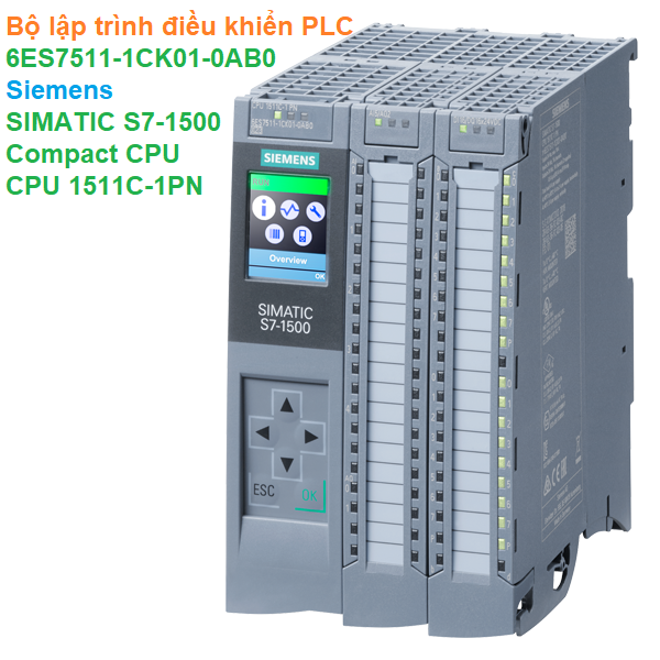
 3,612
3,612