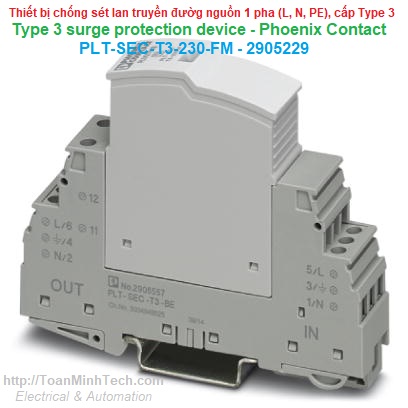


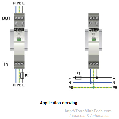
-Type-3-surge-protection-device-PLT-SEC-T3-230-FM-2905229.png)
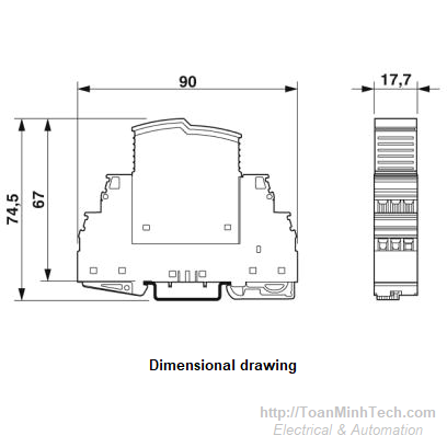
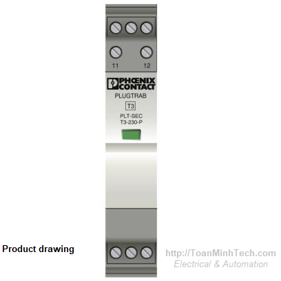
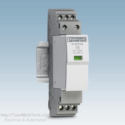
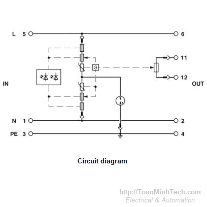
| Height | 90 mm |
| Width | 17.7 mm |
| Depth | 74.5 mm (incl. DIN rail 7.5 mm) |
| Horizontal pitch | 1 Div. |
| Degree of protection | IP20 |
| Ambient temperature (operation) | -40 °C ... 80 °C |
| Ambient temperature (storage/transport) | -40 °C ... 80 °C |
| Altitude | ≤ 2000 m (amsl (above mean sea level)) |
| Permissible humidity (operation) | 5 % ... 95 % |
| Shock (operation) | 30g (Half-sine / 11 ms /3x, X, Y, Z) |
| Vibration (operation) | 5g (10 ... 150 Hz/20 cycles/axis/X, Y, Z) |
| IEC test classification | III |
| T3 | |
| EN type | T3 |
| IEC power supply system | TT |
| TN-S | |
| Number of ports | One |
| Mode of protection | L-N |
| L-PE | |
| N-PE | |
| (L+) - (L-) | |
| (L+/L-) - PE | |
| Mounting type | DIN rail: 35 mm |
| Color | light grey RAL 7035 |
| traffic grey A RAL 7042 | |
| Housing material | PA 6.6-FR 20% GF |
| PA 6.6-FR | |
| Degree of pollution | 2 |
| Flammability rating according to UL 94 | V-0 |
| Type | DIN rail module, two-section, divisible |
| Number of positions | 2 |
| Surge protection fault message | Optical, remote indicator contact |
| Nominal voltage UN | 230 V AC (TN-S) |
| 230 V AC (TT - only in use with RCD) | |
| Nominal frequency fN | 50 Hz (60 Hz) |
| Maximum continuous voltage UC | 264 V AC |
| 230 V DC | |
| Rated load current IL | 26 A (30 °C) |
| Residual current IPE | ≤ 5 µA |
| Nominal discharge current In (8/20) µs | 3 kA |
| Standby power consumption PC | ≤ 275 mVA (at UREF) |
| ≤ 300 mVA (at UC) | |
| Reference test voltage UREF | 255 V AC |
| Combination wave UOC | 6 kV |
| Voltage protection level Up (L-N) | ≤ 1.35 kV |
| Voltage protection level Up (L-PE) | ≤ 1.5 kV |
| Voltage protection level Up (N-PE) | ≤ 1.5 kV |
| TOV behavior at UT (L-N) | 440 V AC (5 s / withstand mode) |
| 440 V AC (120 min / withstand mode) | |
| TOV behavior at UT (L-PE) | 440 V AC (5 s / withstand mode) |
| 440 V AC (120 min / withstand mode) | |
| 1455 V AC (200 ms / safe failure mode) | |
| TOV behavior at UT (N-PE) | 1200 V AC (200 ms / safe failure mode) |
| Response time tA (L-N) | ≤ 25 ns |
| Response time tA (L-PE) | ≤ 100 ns |
| Response time tA (N-PE) | ≤ 100 ns |
| Short-circuit current rating ISCCR | 1.5 kA AC |
| 0.25 kA DC | |
| Max. backup fuse with branch wiring | not required |
| Maximum backup fuse for through wiring | 25 A (gG / B / C) |
| Switching function | N/C contact |
| Operating voltage | 250 V AC |
| 125 V DC (200 mA DC) | |
| Operating current | 3 A AC |
| 1 A DC (30 V DC) | |
| Connection method | Screw connection |
| Conductor cross section flexible | 0.2 mm² ... 2.5 mm² |
| Conductor cross section solid | 0.2 mm² ... 4 mm² |
| Conductor cross section AWG | 24 ... 12 |
| Screw thread | M3 |
| Tightening torque | 0.8 Nm |
| Stripping length | 8 mm |
| Connection method | Screw connection |
| Conductor cross section flexible | 0.2 mm² ... 2.5 mm² |
| Conductor cross section solid | 0.2 mm² ... 4 mm² |
| Conductor cross section AWG | 24 ... 12 |
| Screw thread | M3 |
| Tightening torque | 0.8 Nm |
| Stripping length | 8 mm |
| SPD Type | 4CA |
| Maximum continuous operating voltage MCOV | 255 V AC |
| 230 V DC | |
| Nominal voltage | 230 V DC |
| Rated load current IL | 25 A |
| Mode of protection | L-N |
| L-G | |
| N-G | |
| (L+) - (L-) | |
| (L+) - G | |
| (L-) - G | |
| Power distribution system | 1 |
| Nominal frequency | 50/60 Hz |
| Measured limiting voltage MLV (L-N) | 1290 V |
| Measured limiting voltage MLV (L-G) | 1310 V |
| Measured limiting voltage MLV (N-G) | 1310 V |
| Measured limiting voltage MLV (L+) - (L-) | 1290 V |
| Measured limiting voltage MLV (L+) - G | 1310 V |
| Measured limiting voltage MLV (L-) - G | 1310 V |
| Nominal discharge current In | 3 kA |
| Tightening torque | 5 lbf-in. ... 7 lbf-in. |
| Conductor cross section AWG | 14 ... 12 |
| Conductor cross section AWG | 14 ... 12 |
| Tightening torque | 5 lbf-in. ... 7 lbf-in. |
| Standards/specifications | IEC 61643-11 2011 |
| EN 61643-11 2012 |
| China RoHS | Environmentally Friendly Use Period = 50 |
| For details about hazardous substances go to tab “Downloads”, Category “Manufacturer's declaration” |
| eCl@ss 5.1 | 27130801 |
| eCl@ss 6.0 | 27130806 |
| eCl@ss 8.0 | 27130806 |
| eCl@ss 9.0 | 27130806 |
| ETIM 5.0 | EC000942 |
| ETIM 6.0 | EC000942 |
| UNSPSC 13.2 | 39121620 |
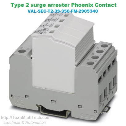 Chống sét Phoenix Contact VAL-SEC-T2-3S-350-FM - 2905340 | Sét lan truyền 3PGiá tốt nhất xem...0909186879 Email
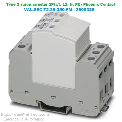 Chống sét Phoenix Contact VAL-SEC-T2-2C-350-FM - 2905337 | Sét lan truyền 2PGiá tốt nhất xem...0909186879 Email
 Chống sét Phoenix Contact VAL-SEC-T2-2S-350-FM - 2905338 | Sét lan truyền 2P T2Giá tốt nhất xem...0909186879 Email
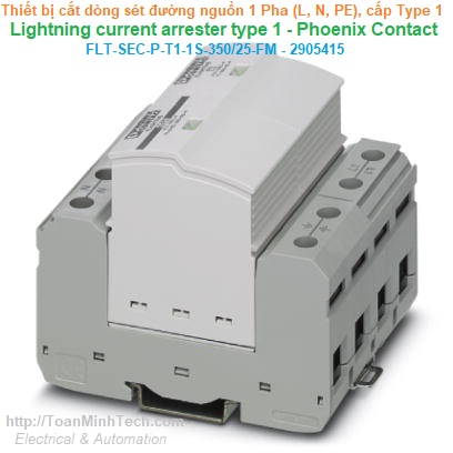 Chống sét Phoenix Contact FLT-SEC-P-T1-1S-350/25-FM - 2905415 | Lan truyền 1PGiá tốt nhất xem...0909186879 Email
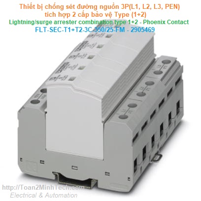 Chống sét Phoenix Contact FLT-SEC-T1+T2-3C-350/25-FM - 2905469 | Cắt-Lọc sétGiá tốt nhất xem...0909186879 Email
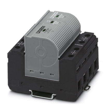 Chống sét lan truyền Phoenix Contact FLT-CP-1S-350 - 2859738 | T1+T2 1AC 100kAGiá tốt nhất Xem...0909186879 Email
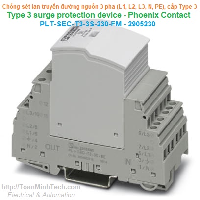 Thiết bị chống sét lan truyền bảo vệ nguồn 3 pha (L1, L2, L3, N, PE) Type 3 - Phoenix Contact - PLT-SEC-T3-3S-230-FM - 2905230Giá tốt nhất Xem...0909186879 Email
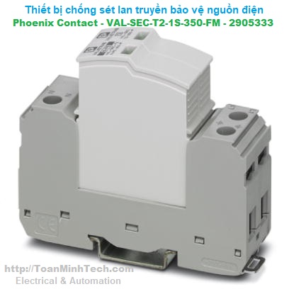 Chống sét Phoenix Contact VAL-SEC-T2-1S-350-FM - 2905333 | Sét lan truyền 1P(L, N, PE) T2Giá tốt nhất Xem...0909186879 Email
 Chống sét Phoenix Contact PLT-SEC-T3-230-FM - 2905229 | Sét lan truyền 1P(L, N, PE) T3Giá tốt nhất Xem...0909186879 Email
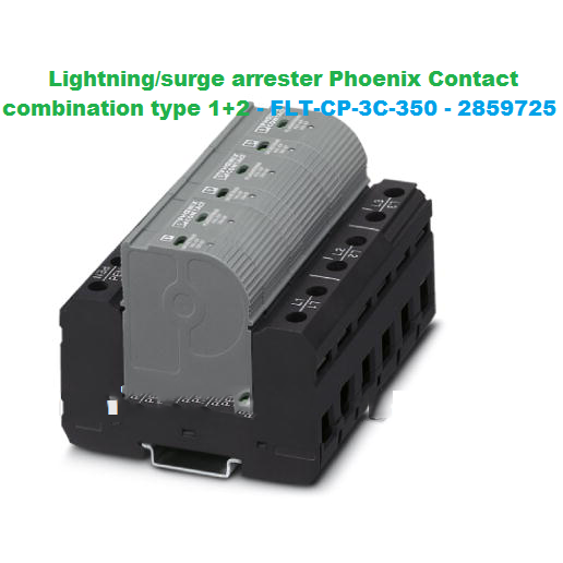 Bộ chống sét lan truyền kết hợp Type 1+2, 3 pha Phoenix Contact FLT-CP-3C-350Giá tốt nhất Xem...0909186879 Email
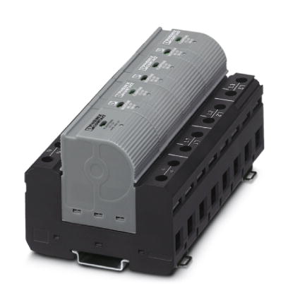 Bộ Chống sét Phoenix Contact FLT-CP-3S-350 - 2859712Giá tốt nhất Xem...0909186879 Email
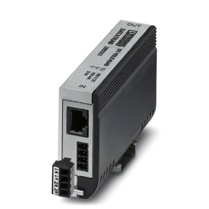 Chống sét viễn thông Phoenix Contact DT-TELE-RJ45 - 2882925Giá tốt nhất Xem...0909186879 Email
 Chống sét Phoenix Contact VAL-SEC-T2-3S-350-FM - 2905340 | Sét lan truyền 3P (L1, L2, L3, N, PE) T2Giá tốt nhất Xem...0909186879 Email
-FLT-SEC-T1+T2-3S-35025-FM-2905470.jpg) Chống sét Phoenix Contact FLT-SEC-T1+T2-3S-350/25-FM - 2905470 | Cắt-Lọc sét 3P(L1, L2, L3, N, PE) T(1+2)Giá tốt nhất Xem...0909186879 Email
Chống sét Phoenix Contact FLT-SEC-T1+T2-3S-350/25-FM - 2905470 | Cắt-Lọc sét 3P(L1, L2, L3, N, PE) T(1+2)Giá tốt nhất Xem...0909186879 Email