Đầu báo cháy (khói-nhiệt) Tyco 851PH | 516.850.055
Thiết bị phát hiện khói và nhiệt quang học đa cảm biến Tyco 851PH (Model 516.850.055) là một thiết bị tiên tiến có thể định địa chỉ. Được thiết kế cho hệ thống báo cháy Minerva MX, thiết bị này được sử dụng rộng rãi trong môi trường công nghiệp và hàng hải để phát hiện đám cháy một cách đáng tin cậy, từ cháy âm ỉ đến cháy bùng.
Thông số kỹ thuật và tính năng chính của Đầu báo khói-nhiệt Tyco 851PH Model 516.850.055
- Công nghệ cảm biến kép: Kết hợp phát hiện khói quang học và cảm biến nhiệt để cải thiện độ chính xác phản hồi và giảm báo động giả.
- Bộ cách ly đường dây tích hợp: Bộ cách ly đường dây ngắn mạch tích hợp giúp duy trì tính toàn vẹn của hệ thống trong trường hợp lỗi dây dẫn.
- Chế độ nhạy: Hoạt động ở các chế độ và độ nhạy được lựa chọn động, đã được phê duyệt và điều chỉnh phù hợp với các điều kiện môi trường cụ thể.
- Bảo trì: Có tính năng bù trôi mở rộng để duy trì sự ổn định theo thời gian và hỗ trợ giao tiếp hồng ngoại hai chiều với Công cụ quản lý kỹ thuật 850EMT.
- Đèn LED báo hiệu: Có các đèn LED báo hiệu chuyên dụng cho các trạng thái Cháy, Cách ly và Lỗi.
- Môi trường & Trọng lượng: Phạm vi nhiệt độ hoạt động từ -25°C đến +70°C với độ ẩm không ngưng tụ lên đến 95%. Trọng lượng thiết bị khoảng 76g.
- Chứng nhận: Được chứng nhận SIL2 và được các tổ chức phân loại lớn phê duyệt cho việc sử dụng trên tàu biển và tàu ngoài khơi.
Tính năng, đặc điểm
- Đầu dò khói quang, nhiệt hoặc đa cảm biến
- Thiết kế buồng nâng cao
- Bù trôi kéo dài
- Bộ cách ly dòng ngắn mạch tích hợp
- Phạm vi tùy chọn màu sắc
- Lập trình từ xa qua liên kết hồng ngoại
- AS 7240.5 Liệt kê (đầu báo nhiệt)
- AS 7240.7 Liệt kê (đầu báo khói)
Mô tả sản phẩm
- 850PH Quang điện / Nhiệt
- Chỉ nhiệt 850H
- Chỉ khói quang 850P
Các máy dò đa cảm biến có thể được cấu hình để hoạt động ở một trong các chế độ sau:
- Khói tăng cường nhiệt cộng với phát hiện nhiệt
- Chỉ phát hiện khói tăng cường nhiệt
- Chỉ phát hiện khói
- Tỷ lệ phát hiện nhiệt tăng và nhiệt độ cố định
- Chỉ phát hiện nhiệt độ cố định nhiệt
Các máy dò đa cảm biến MX Series 850 truyền các giá trị kỹ thuật số thể hiện mức độ khói / CO / nhiệt tại các cảm biến đến Thiết bị chỉ báo và điều khiển Tyco MX (CIE). Phần mềm CIE diễn giải các giá trị được trả về, phản hồi (ví dụ: để tăng cảnh báo) theo chế độ phát hiện được định cấu hình trong phần mềm. Bằng cách sử dụng nhiều cảm biến, các thuật toán phát hiện CIE có thể kết hợp các tín hiệu theo các cách khác nhau để đạt được phát hiện tối ưu.
Các máy dò 850 Series sẽ cắm vào các căn cứ sau:
- Cơ sở liên tục 4B-C - sử dụng cho hầu hết các cài đặt
- Cơ sở cách ly 4B-I
- Cơ sở cách ly 5BI
- Cơ sở Rơle 814RB
- Cơ sở âm thanh 802SB
- Cơ sở phổ thông 4B
- Cơ sở phổ thông 5B
- Cơ sở phổ cập MUB
Lưu ý rằng bộ cách ly ngắn mạch vòng lặp tích hợp sẽ chỉ hoạt động với cơ sở 4B-C. Cơ sở này cũng duy trì tính liên tục của vòng lặp nếu máy dò bị loại bỏ.
Thông số kỹ thuật
Specifications
|
850PH
|
850H
|
850P
|
| Mechanical (less base) |
Photoelectric/Heat |
Heat only |
Photoelectric |
| Height |
43mm |
43mm |
43mm |
| Diameter |
109mm |
109mm |
109mm |
| Weight |
76g |
81g |
76g |
| Electrical |
|
|
|
| Loop Voltage |
20V to 40VDC addressable loop voltage is provided by the MX CIE |
| Quiescent Current (typical) |
330μA |
290μA |
330μA |
| Alarm Current1 |
3mA |
3mA |
3mA |
| Alarm Current2 |
10mA |
10mA |
10mA |
| Remote Indicator |
Tyco E500Mk2 typical for all detectors |
| Max. Detectors per Loop3 |
250/200 |
250/200 |
250/200 |
| Normal Environmental |
|
|
|
| Ambient Temperature4 |
–25°C to +70°C |
–25°C to +70°C7 |
–25°C to +70°C |
| Storage Temperature |
–40°C to +80°C |
–40°C to +80°C |
–40°C to +80°C |
| Relative Humidity5 |
95% |
95% |
95% |
| ActivFire Listed |
afp-2928 |
afp-2929 |
afp-2930 |
| Standards |
AS 7240.5-20046 |
AS 7240.5-20046 |
AS 7240.7-2007 |
| |
AS 7240.7-2007 |
|
|
Part Numbers
|
516.850.051.E |
516.850.053.E |
516.850.052.E |
1. Remote Indicator not fitted 2. With Remote Indicator fitted 3. Depends on the CIE used, i.e., VIGILANT MX1 / VIGILANT MX4428. Refer to CIE manuals for design limitations 4. A2S/A2R Heat detection enabled, 45°C max. 5. Maximum, non condensing 6. 850H heat sensor is A2S, A2R, CS and CR, 850PH heat sensor is A2S and A2R only. 7. Short term to 90°C 8. Not available with VIGILANT MX4428
Hướng dẫn lắp đặt và Đấu dây Installation - Wiring

The MX CIE can be programmed to illuminate a Remote Indicator for detectors in alarm other than the detector base to which the
Indicator is connected.
Typical Wiring for MX1
Addressable systems using the 4B-C Continuity base.
Wiring
Cables should be arranged at each side of the terminal screw. A maximum of two 1.5mm2 cables or one 2.5mm2 cable can be fitted to one terminal. Any additional cables (such as Remote Indicator) should be fitted with suitable fork or eyelet crimp terminal lugs. The installation should comply with AS 1670.1 or NZS 4512, as applicable.
| 4B Loop Cabling |
4B-C Loop Cabling |
4B-I Loop Cabling |
L (-In/Out) L1 (+In/Out).
A remote indicator may be connected between loop positive L1 (+In/Out) and terminal R (-ve). Terminal L2 must not be used. |
L (-In) M (-Out) L1 (+In/Out).
A remote indicator may be connected between loop positive L1 (+In/Out) and terminal R (-ve). Terminal L2 must not be used. |
L2 (-In) M (-Out) L1 (+In/Out).
A remote indicator may be connected between loop positive L1 (+In/Out) and terminal R (-ve). Terminal L must not be used. |
Positioning of Detectors
The 850 series of detectors are not suitable for use where they may be exposed to condensing moisture, mist or water spray.
When mounting on a narrow beam or where condensation may enter the rear of the detector, the deckhead mounting base 4B-DHM (part no. 517.050.051) should be used. Installation of all detectors should be carried out in accordance with AS 1670.1 or NZS4512.
Cable penetrations should be sealed when positive or negative pressures in ceiling spaces may affect the performance of or
contaminate the installed detectors.
Maintenance and Service
The Tyco MX addressable system should be maintained in accordance with AS 1851 or NZS4512.
The Tyco X300 Smoke Tester, X461 Heat Tester and CO test gas (517.001.262) may be used for testing in-situ.
Rotating the detector anticlockwise past an indent to the park position disconnects the detector from the circuit whilst still
retaining it in the base, allowing wiring testing etc. (Note that insulation testing must not be done where isolator bases are used). Depressing the plunger at the side of the base allows the detector to be rotated back into its operating position. The CO sensing element has an expected service life of 10 years.
The MX CIE can be set to report when the time period has been exceeded and the CO detector requires replacement. Applications Warning In many fires, hazardous levels of smoke and toxic gas can build up before a heat detection device will initiate an alarm. In cases where life safety is a factor, the use of smoke and/or CO detection is highly recommended. Heat detectors are not considered to provide life safety protection and are generally used where property protection is desired, but smoke or CO detectors cannot be used. Typical heat detector applications are satisfied by use of rate-of-rise and fixed temperature electronic detectors. The addition of rate-of-rise operation provides faster heat detection for use where temperature fluctuations are controlled and less than 6°C/min. Where temperatures may fluctuate more quickly, use fixed temperature detection only (Type A2S or Type CS).


 dienelectrics@gmail.com
 0909186879
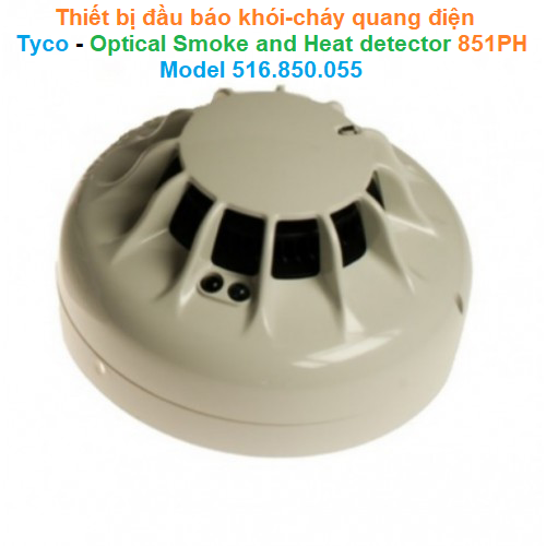
 5,717
5,717


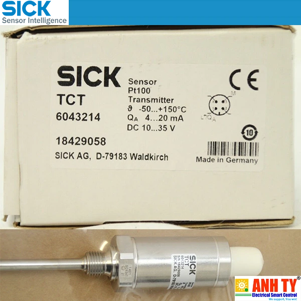 Cảm biến nhiệt độ -50...+150°C Pt100 4-20mA Sick TCT-1AAG12506MZ | 6043214Giá tốt nhất xem...0909186879 Email
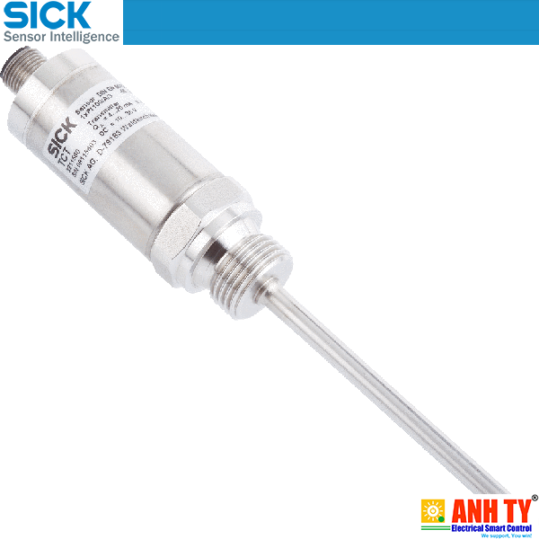 Cảm biến nhiệt độ -50...+150°C Pt100 4-20mA Sick TCT-1PAG10253MZ | 6043164Giá tốt nhất xem...0909186879 Email
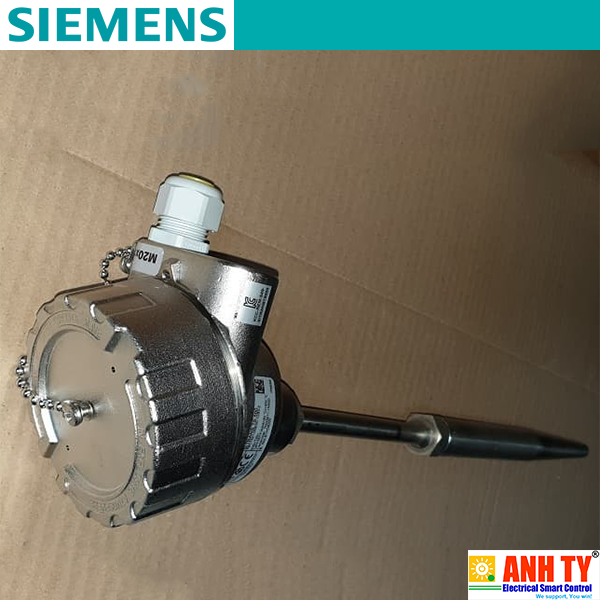 Cảm biến nhiệt độ Siemens 7MC7521-0NE00-1UB3-Z A02 C11 E00 T20 Y01Giá tốt nhất xem...0909186879 Email
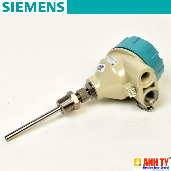 Cảm biến nhiệt độ Siemens 7MC7512-1CB25-9AK1-Z E00+N1DGiá tốt nhất xem...0909186879 Email
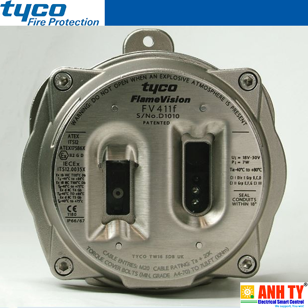 Đầu báo lửa hồng ngoại Tyco FV411f (516.300.411) | Triple IR Flame DetectorGiá tốt nhất xem...0909186879 Email
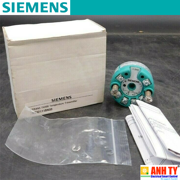 Siemens 7NG3211-1BN00 | Temperature transmitter SITRANS TH200 -Bộ chuyển phát tín hiệu nhiệt Lắp vào đầu kết nối Loại B DIN 43729 2-Wire 4-20mA Khả trình Có cách ly điện Bảo vệ nổ FM cFMUSGiá tốt nhất Xem...0909186879 Email
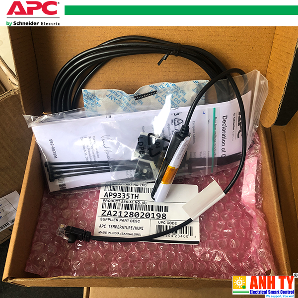 APC AP9335TH | Temperature & Humidity sensor -Cảm biến Nhiệt độ và Độ ẩm RJ45 cho Data Center or Network ClosetGiá tốt nhất Xem...0909186879 Email
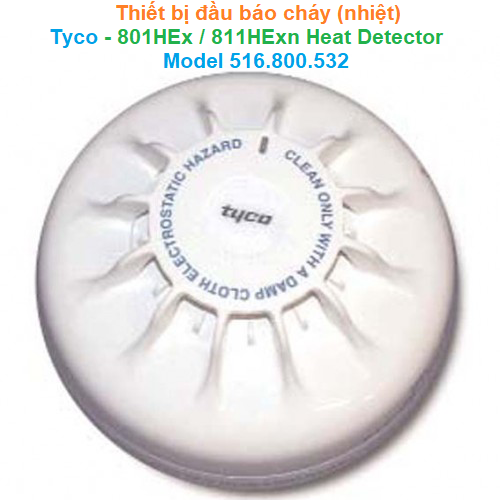 Thiết bị đầu báo cháy (nhiệt) - Tyco - 801HEx/811HExn Heat Detector Model 516.800.532Giá tốt nhất Xem...0909186879 Email
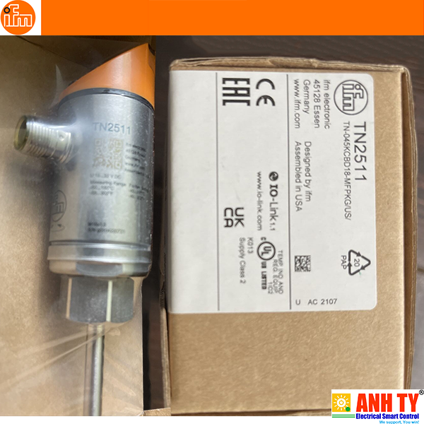 Cảm biến nhiệt độ có thông số hiển thị Temperature sensor with display - IFM - TN2511 (TN-045KCBD18-MFPKG/US/)Giá tốt nhất Xem...0909186879 Email
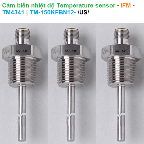 Cảm biến nhiệt độ Temperature sensor - IFM - TM4341 (TM-150KFBN12-)Giá tốt nhất Xem...0909186879 Email
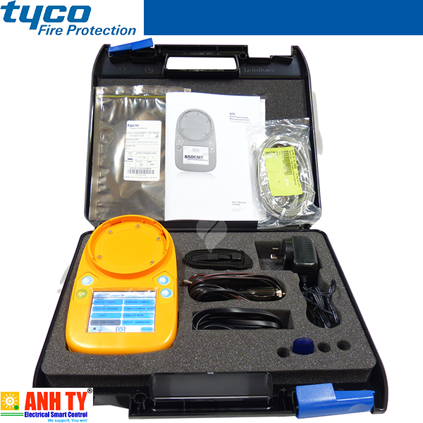 Tyco 850EMT MX Service Tool KIT -Bộ lập trình đầu báo cháy-khói cho 850 SeriesGiá tốt nhất Xem...0909186879 Email
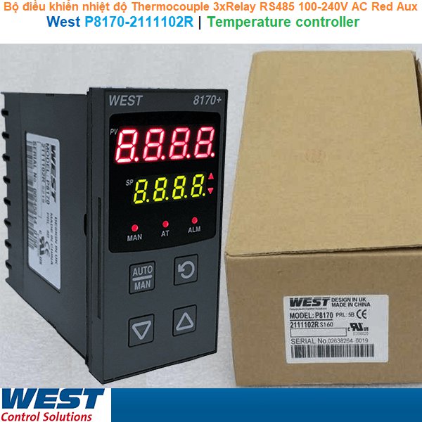 West P8170-2111102R | Temperature Controller -Bộ điều khiển nhiệt độ Giá tốt nhất Xem...0909186879 Email
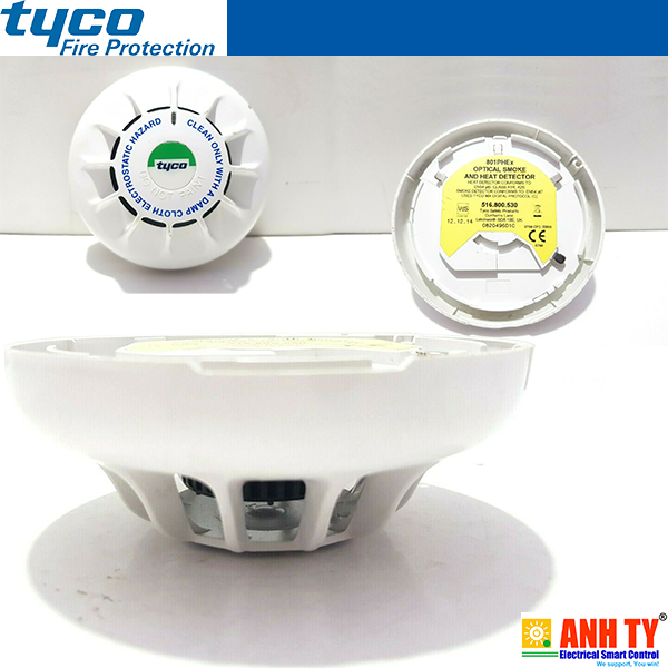 Tyco 801PHex (516.800.530) | Optical smoke heat detector -Đầu báo khói-cháy quang đa năngGiá tốt nhất Xem...0909186879 Email


