Bộ cài đặt chương trình Tyco 801AP MX Programming & Service tool | 516.800.918
(cho các thiết bị địa chỉ MX của Tyco)
Tyco 801AP MX Programming & Service Tool 516.800.918
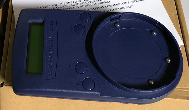
The Tyco 801AP MX Service Tool is a powerful and flexible tool, designed to assist in the installation, commissioning, diagnostics and service of Tyco MX Fire Detection Systems.
Tyco 801AP allows all of the MX addressable devices to be interrogated, tested and programmed. It has a 32 character backlit LCD alphanumeric display, arranged in 2 rows of 16 characters and 4 softkeys.
Key features include
- Read/write the detector/ancillary address
- Display date of manufacture and commissioning
- Programming of the LED
- Display serial number
- Display temperature/ CO levels / smoke obscuration
- Testing the detector remote LED and control outputs
- Perform the detector self verification test function
- Displaying detector dirtiness level
- Controlling ancillary outputs
- Reading ancillary statuses
- Power management options
- Product Code: 801AP (516.800.918)
801AP MX SERVICE TOOL USER INSTRUCTIONS
INTRODUCTION
The 801AP MX Service Tool is used to program the loop address into MX addressable devices. (A Quick Functional Reference Table is detailed on page 9).
The 801AP displays information and performs tests on devices. It has a 32 character backlit LCD alphanumeric display, arranged in 2 rows of 16 characters and four ‘softkeys’, F1, F2, F3 and F4. (The display format is shown in Fig. 5).
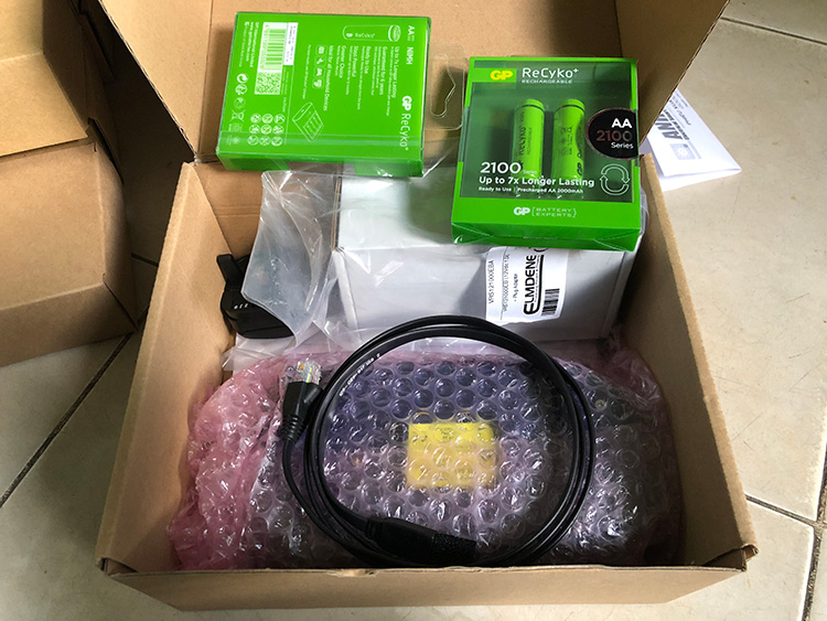
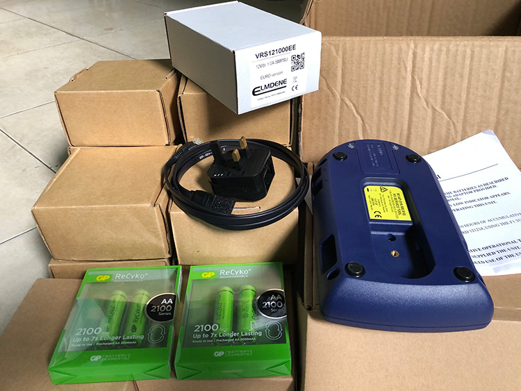
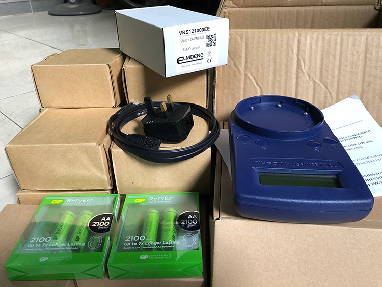
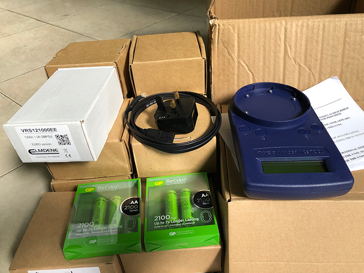
Power for the 801AP is derived from 4 AA size nickel metal hydride rechargeable batteries. It may be run from an unregulated +12V dc input, ie, car cigarette lighter connection or 110/230V ac mains adaptor, both of which will recharge the batteries as well. The 801AP consists of the following:
- MX Service Tool
- Service Tool to ancillary connector lead
- 110 or 230V ac adaptor plus lead
- 4 x rechargeable AA size Nickel Metal Hydride batteries
The 801AP is designed to be used as a desktop unit, clipped to a trouser belt or be carried with a shoulder strap. The 801AP has four external connections:
DC IN +12V
From car cigarette lighter or 110/230V ac mains adaptor
AUX
Ancillary connection port
PC
PC connection port for use with MX CONSYS (not yet available)
μP
Internal micro-processor program download port for use with PMS - Program Management Software.
Detectors are programmed by placing the detector onto the 801AP and turning clockwise until fully engaged.
Ancillaries are programmed via the AUX port on the 801AP. The ancillary programming cable consists of an RJ11 connector at one end and a custom moulded connector at the other end.

TECHNICAL SPECIFICATION
MECHANICAL
Dimensions
HWD: 48 x 200 x 112mm
Weight
801AP Service Tool: 0.36kg
801AP Service Tool + batteries: 0.5kg
Materials
Top: FR ABS Dark Blue
Bottom: FR ABS Dark Blue
ELECTRICAL
Batteries
4 x rechargeable AA size
Nickel Metal Hydride
Operating Time (Batteries only)
Up to 15 hours (dependent on battery charge and usage)
The ac adaptor is required when testing high current MX addressable devices, including the SAM800/ SAB800/ SAB801.
ENVIRONMENTAL
- Operating Temperature: 0°C to +45°C
- Storage Temperature: 0°C to +50°C
- Relative Humidity: 90% (non-condensing)
- Battery Disposal: No special considerations are applicable in the UK at time of writing. (Check with local authorities).
EMC
The 801AP MX Service Tool meets the requirements of the EU EMC Directive 89/336/EEC.

OPERATION
IMPORTANT
- FULLY CHARGE THE BATTERIES FOR 10 HOURS BEFORE USING FOR THE FIRST TIME
- RECHARGE THE BATTERIES AS SOON AS THE LOW BATTERY INDICATOR APPEARS.
- DO NOT OPEN BATTERY LID WHILE THE UNIT IS SWITCHED ON.
STARTING UP
INSTALLING BATTERIES
To install/change the batteries, proceed as follows:
a) Unscrew the two screws on the base of the 801AP, using a cross-point screwdriver, holding the battery compartment cover whilst removing it.
b) Insert the batteries ensuring correct polarity as shown inside the battery compartment.
c) Replace the battery compartment cover and screw down.
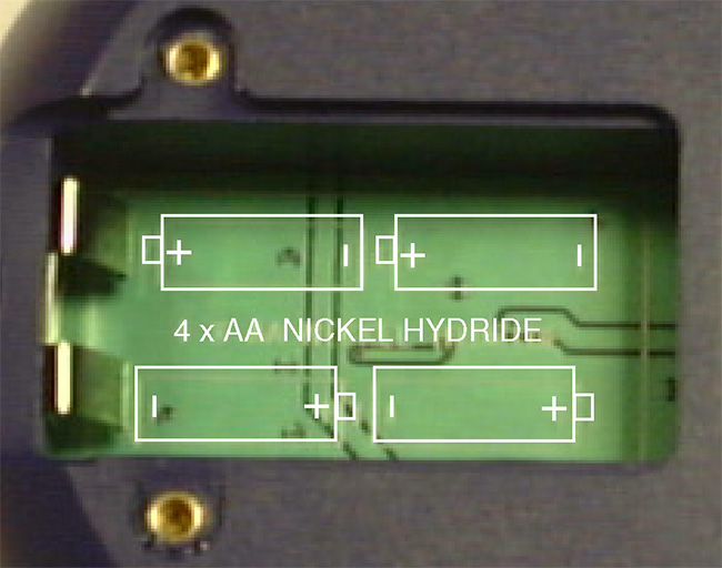
Fig. 2 Battery Compartment
CAUTION
ENSURE ONLY NICKEL METAL HYDRIDE RECHARGEABLE BATTERIES ARE USED AND FULLY CHARGED BEFORE USE.
CHARGING AND MAINS USE
The 801AP has its own built-in charging circuit, powered by the mains adaptor. The batteries are boost-charged for 4-5 hours and reach full charge within 10 hours.
The 801AP can be powered from the mains supply using the DC adaptor. If batteries are installed, this allows them to be charged at the same time. For low battery indicator.
PASSWORD PROTECTION
The 801AP MX Service Tool is switched ON/OFF by pressing any button for more than 3 seconds. The following example screen showing the software revision number, is displayed for 2 seconds when the Service Tool is switched on:

Note that the ‘E’ displayed stands for English version. (appropriate letters are used for other languages). The Service
Tool then displays:

Note: The following information on Password Protection is CRUCIAL to the operation of the MX Service Tool.
The Service Tool requires a 6-digit password to be entered. The password is different for each service tool and will be issued by the respective branch office.
The password uses only the digits 1 to 4, and may be entered by pressing the corresponding buttons F1 to F4; eg, button F1 to enter 1, button F2 to enter 2, etc.
The user has 3 attempts to enter the correct code. On the 4th attempt the following screen is displayed:

The user must telephone the branch office to get the correct 6-digit password at this point.
WARNING
FAILURE TO ENTER THE CORRECT PASSWORD AT THE FOURTH ATTEMPT WILL RESULT IN THE SERVICE TOOL SWITCHING OFF AND ALLOWING ONLY ONE ATTEMPT ON SUBSEQUENT POWERING UP OF THE UNIT.
The password has an expiry time associated with it.
The hours left indicates the actual usage (switched on) time remaining.
CAUTION
- ONCE THE HOURS LEFT REACHES ZERO, THE SERVICE TOOL BECOMES
- INOPERABLE AND MUST BE RETURNED TO THE BRANCH OFFICE.
When there is less than 50 hours, the expiry time appears. The screen displays the expiry time in the form of ‘Hours Left’:

On successful entry of the password, the following screen is displayed:

This is the start of the main menu options, which are discussed further in para. 3.5.
CONNECTING TO A DEVICE
Detectors are inserted as shown in Fig. 3. Use the marking on the service tool (above F1 button) to align the detector. Place detector in position 1 to engage and then twist clockwise to position 2 to lock.
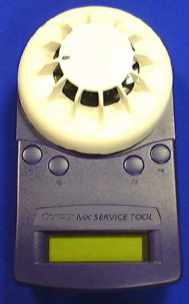
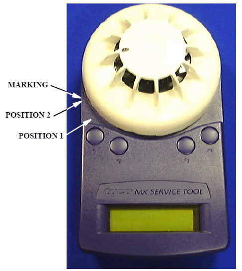 Fig. 3 Connecting a detector
Ancillaries are connected to the ‘AUX’ socket using the ancillary connection lead connector lead as shown in Fig. 4.
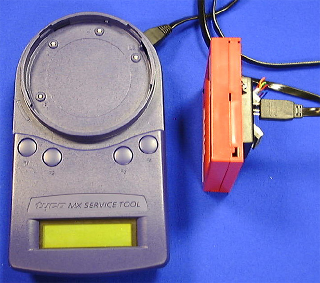 Fig. 4 Connecting to an ancillar
Note
Fig. 4 Connecting to an ancillar
Note
1) It is good practice to connect only a detector or ancillary at any one time. However, the Service Tool is equipped with a port interlock feature. When the ancillary lead is connected to the ‘Aux’ socket, communication with the detector will be disabled. When the ancillary lead is removed, the detector will be able to communicate.
2) On older models of the 801AP Service Tool, the detector had priority for communication. Newer models of the 801AP, where the ancillary has priority, can be identified by the C-tick mark on the product identity label on the underside of the tool (see Fig. 10 on Page 8)
3) The 801AP may be connected to an ancillary device that is also connected to and powered from the addressable loop. However, a ‘No Response’ fault for that device may be generated at the Control Panel under these conditions.
WARNING
SPECIAL CARE MUST BE TAKEN WHEN CONNECTING TO A DEVICE ON THE ADDRESSABLE LOOP TO PREVENT UNWANTED ACTION IN OTHER EQUIPMENT EG, EXTINGUISHING SYSTEMS.
BUTTON OPERATION
The screen displays the start of the main menu as shown in Fig. 5
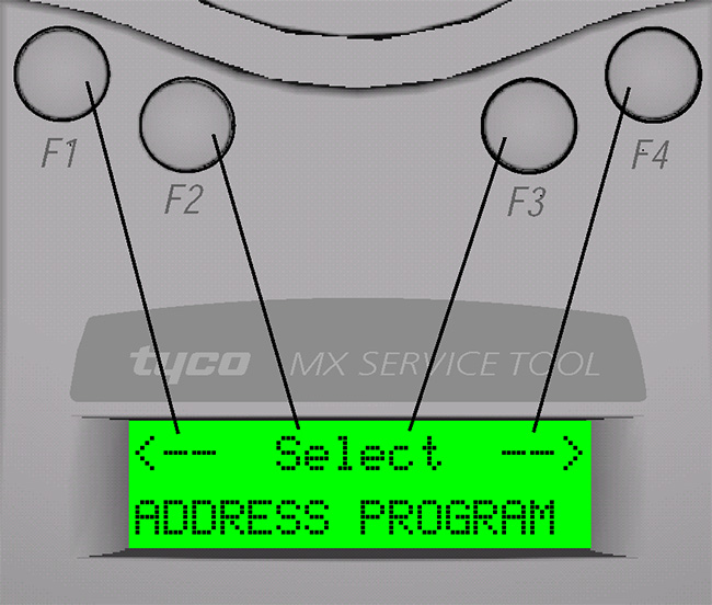 Fig. 5 First Display Screen of the main menu
The main menu can always be identified by the word ‘Select’ between two arrows on the top line of the display. The bottom line of the main menu displays the option.
The top line position of text is always shown in relation to the F1-F4 buttons above. In the Main Menu:
- F1 scrolls left through the main menu options
- F2 or F3 select the menu option displayed
- F4 scrolls right through the main menu options
When an option is selected from the main menu, the display uses the format shown in Fig. 6:
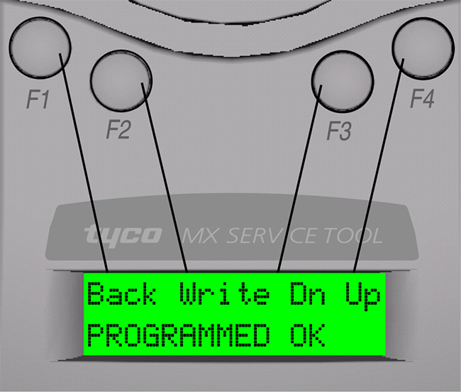 Fig. 6 Example of Writing an address
The bottom line displays information to the user. The top line displays the available options.
Note: The position of the options on the top line is relative to the buttons.
Fig. 6 shows
- F1 selecting ‘Back’
- F2 selecting ‘Write’
- F3 selecting ‘Dn’ (for down)
- F4 selecting ‘Up’
In some cases there may be fewer options available.
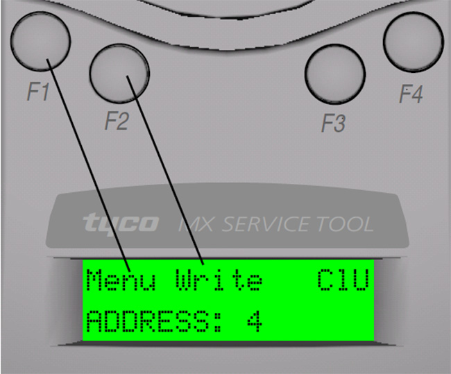 Fig. 7 Example of Reading an addres
Fig. 7 shows
Fig. 7 Example of Reading an addres
Fig. 7 shows
- F1 selecting ‘Menu’
- F2 selecting ‘Write’
- F3 no action
- F4 clear used memory map
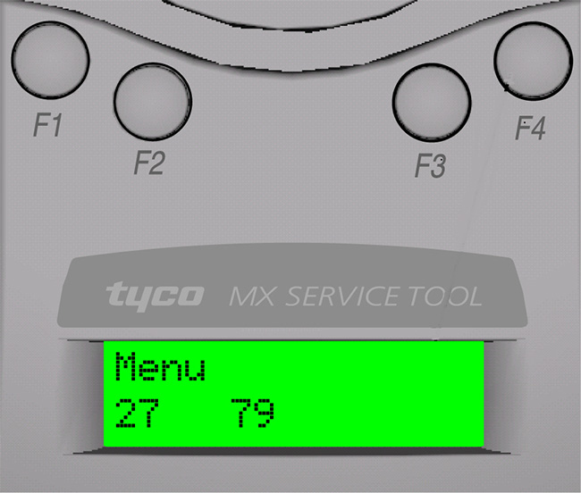 Fig. 8 Example of Single Optio
In Fig. 8 pressing F1 selects the ‘Menu’, F2-F4 are redundant here.
FUNCTIONALITY
ADDRESS PROGRAM

The main menu starts with ADDRESS PROGRAM. Press buttons F2 or F3 to choose ‘Select’ and the address of the device is displayed (eg, address 4).

- Use ‘Write’ to program the device with a new address
- ‘Menu’ to return to the main menu
- ClU to clear the memory map of used addresses
Note:
Whenever ‘Menu’ appears on the display, this always returns to the main menu.
The Service Tool saves a memory map of the addresses that have been programmed. To erase this, select menu and choose Clear Used ‘ClU’.
If ‘Write’ is selected, the following screen is displayed:

- Use ‘Up’ to increase the address number
- ‘Dn’ to decrease it
- ‘Write’ to program the address displayed
- ‘Back’ to return to the previous screen
If ‘Write’ is selected then the following message will appear for 2 seconds:

This is followed by:

Having programmed an address, the Service Tool moves to the next sequential unused address.
If an address has already been used, the Service Toolindicates:

If the user then decides to use a previously used address, the following screen is displayed:

Press ‘Write’ and the Service Tool displays
‘PROGRAMMED OK’ briefly and then displays the next available sequential address.
ANALOGUE VALUES
ANALOGUE VALUES displays the analogue values of the attached device.

The above example shows a device with 2 channels, eg, an Optical/ Heat detector, where channel 1 is the optical value and channel 2 is the heat value. Press ‘Menu’ to return to the main menu.
Note:
1) Only displayed if channel 3 is used on a device.
2) These are the values that the device would transmit to the control panel. The values do NOT include any calibration or correction factors.
MEASURE TEMP
This feature measures temperature in degrees Celsius and degrees Fahrenheit, but is only available on detectors which have a temperature sensing element, ie, Heat only, Optical & Heat and CO & Heat detectors. A typical display is shown in b):
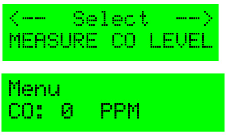
 MEASURE CO LEVEL
For CO detectors only. Gives values for CO levels in the measuring environment. Normal value is zero PPM (partsper-million).
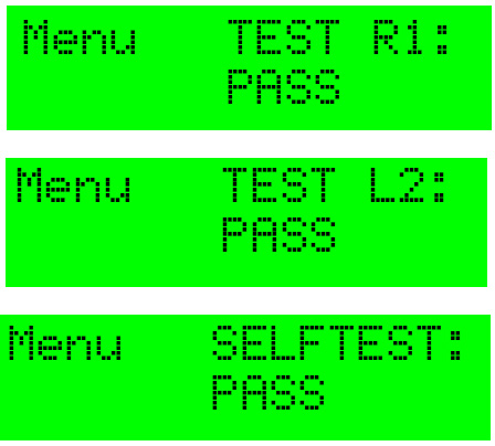
 TEST ALL
This option combines a test on the detector R1 and L2 terminals and tests the detector’s sensor circuitry for units which have this facility.
- The Test R1 terminal tests the remote indicator output.
- The Test L2 terminal tests the functional base interface output.
- The Selftest tests the sensor input circuitry. Completion of the Selftest may require a maximum of 30 seconds.
Following the completion of all three tests, a test report is displayed on the LCD. Each test can result in a PASS, FAIL or NOT AVAILABLE report message.
To start a new test, select the TEST ALL menu to begin.
WAIT is displayed until all tests are completed.
When the tests are complete, the test results are reported on three alternating displays:
Self Test is available on the following types of detectors:
- MX Ionisation.
- MX Optical + Heat (including 814P).
(Optical sensing element only).
- MX CO + Heat
(CO sensing element only).
- MX Flame.
Note:
Self test is NOT available for the heat sensing channels of these detectors.
DIRTINESS

Available for detectors with an optical sensing element only. Indicates the contamination level of the optical chamber. Compares the current optical analogue value as a percentage where 0% would indicate that the analogue value has not changed since manufacture, 100% would indicate that the analogue value has risen to its maximum allowable value (the point at which it would generate a fault).
At 80% or above, the detector should be replaced to avoid the possibility of a fault occurring in the near future.
Note: Dirtiness can be displayed as a negative number if the analogue value has fallen since manufacture.
DEVICE TYPE ID
Device Type ID displays the unique value associated with each addressable device Model No., eg, for Model No.801PH - Type Value 10 is displayed.

Type Value may be cross-referenced to Model No. by referring to Table 2 on Page 10.
DIGITAL INPUTS
This menu option displays the status of the digital inputs in binary and as a decimal number between 0 to 255 for all addressable devices.
The binary number is aligned with the least significant bit on the right as indicated with a small ’L’ character.
 DIGITAL OUTPUTS

The user may set the Digital Output of the addressable device by using the following function buttons, F2 to F4:
Flashing cursor denotes the digit to be set.
- --> + moves the cursor one position to the right
- Tog + toggles between 0 and 1 for each digit
- ‘Set’ + prompts the 801AP to send an instruction to the addressable device
- ‘Menu’ + to return to the main menu options
WARNING
WHEN USING THE SERVICE TOOL WITH AN ANCILLARY DEVICE CONNECTED TO THE ADDRESSABLE LOOP, MAKE SAFE ANY ATTACHED EQUIPMENT, eg, EXTINGUISHING, PLANT SHUTDOWN etc. UNLESS IT IS BEING USED SPECIFICALLY FOR TESTING THE ATTACHED EQUIPMENT.
After ‘Set’ is selected, a message will appear asking for confirmation of the action to send the data to the device, as follows:

An LED test may be performed on addressable devices using the digital output function. Move the cursor to the eigth bit on the far-right and toggle this bit “1”. The LED should illuminate red on all models”.
CUSTOMER CODE
CAUTION
THIS MENU OPTION CHANGES THE CUSTOMER CODE OF THE SERVICE TOOL AND SHOULD ONLY BE USED FOR DE-BUGGING PURPOSES. IT SHOULD BE SET TO 254 NORMALLY.
 Note
Note
1) Communication is only possible if the same customer code is present in the addressable device and the service tool.
2) The addressable device is manufactured with a default code of 254. This is set in the device and cannot be changed.
ADDITIONAL FUNCTIONS
DEVICE POLLING
In all operations that retrieve data from an attached device, the 801AP polls the attached device at a pre-determined interval. This interval is 2 seconds for the ADDRESS PROGRAM function and 5 seconds for all other functions.
 LOW BATTERY
This is indicated by a flashing symbol in the bottom right of the LCD display.
The batteries must be charged using the mains adaptor with its connecting lead plugged into the Service Tool dc input socket.
LCD BACKLIGHT
The display can be temporarily illuminated by pressing any two buttons simultaneously at any time.
AUTO POWER OFF
AUTO POWER OFF is designed to save battery life. If there have been no button presses during the last 5 minutes, the Service Tool automatically turns itself off.
CPU RESET
Note
This function is not normally used.
If the buttons or display are not responding correctly, the Service Tool may be reset. This is done by pushing a small jewellers type screwdriver into the pinhole on the bottom of the Service Tool to actuate a switch.
When a CPU reset is carried out, the Service Tool will start up as described in para 3.2 ‘Password Protection’.
INTRINSICALLY SAFE 800Ex DETECTORS
Intrinsically Safe 800Ex detectors can only be programmed if an Ex dongle adaptor (supplied with the EXI800) is fitted to the ‘AUX’ port of the 801AP Service Tool (see Fig. 9).
Note
On later models of the 801AP Service Tool, the Ex dongle adaptor is not required for programming Intrinsically Safe 800Ex detectors. The applicable models of the 801AP can be identified by the C-tick mark on the product identification label on the underside of the tool. See Fig. 10.
When using with Intrinsically Safe 800Ex devices, the Service Tool must be used in a non hazardous safe area.
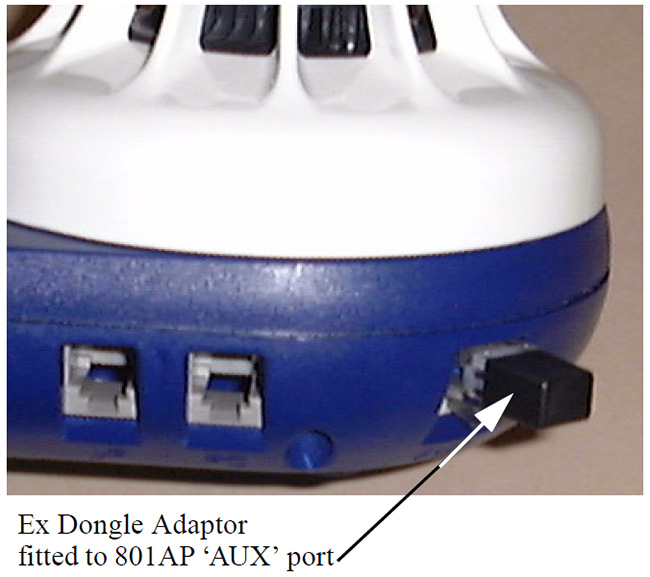 Fig. 9
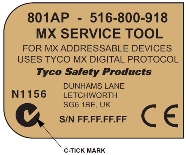 Fig. 10
PROGRAMMING LEAD
The new version of hardware (with the C-tick mark, on the product identification label, Fig. 10) is compatible with download lead 801PL PMS MX Programming Lead (S/C No. 516.800.929) but is not compatible with earlier download lead AVRISP-02 PMS MX Programming Lead (S/C No. 516.800.928)
ACCESSORIES
ACCESSORY KIT (
516.800.923)
Consisting of:
- Carry case
- Car lighter adaptor
- Shoulder strap
SPARES
Spare ancillary lead: 516.800.922
Ancillary lead spare pins (bag of 10): 516.800.924
Functional Reference table
MAIN MENU AND DISPLAY ACTIONS
‘Address Program’
- Read/Writes the address of the connected addressable device
- Reads the stored address map of used addresses
‘Analogue Values’
- Displays the analogue values of the addressable device
‘Measure Temp.’
- Measures temperature in degrees C and F (only available on detectors which have a temperature sensing element)
‘Measure CO Level’
- For CO detectors only. Gives values for CO levels in the measuring environment.
- Normal value is zero PPM (parts-per-million)
‘Test All’
- Performs: a self test if the detector has such a facility remote indicator output functional base interface output
‘Dirtiness’
- Indicates the contamination level of the optical chamber expressed as a percentage, where 100% is the fault level
‘Device Type ID’
- Displays the device type identification value
‘Digital Inputs’
- Displays the status of the digital inputs in addressable devices
‘Digital Outputs’
- Allows the user to set the digital outputs of the addressable device
‘Customer Code’
- Not normally used, but it should be set to the same as the customer code in the device
Low Battery
Indicates Low Battery by using a flashing symbol in the bottom right of the LCD display
CPU Reset
Switch is accessed through a small hole at the rear of the unit near the label
LCD Backlight
The display can be temporarily illuminated by pressing any two buttons simultaneous
Type Values
| Description |
Market |
Model |
Type value |
| Optical smoke + Heat |
Europe |
801PH |
10 |
| Marine |
811PH |
11 |
| Australia |
814PH |
13 |
| IS Baseefa |
801PHEx |
14 |
| France |
816PH |
18 |
| Ex 'n' Baseefa |
811PHExn |
11 |
| Optical Smoke |
Europe |
813P |
15 |
| Australia |
814PH |
17 |
| France |
816PH |
19 |
| High sensitivity optical smoke |
Europe |
801PS |
17 |
| Heat only |
Europe/ France |
801H/ 816H |
20 |
| Marine |
811H |
21 |
| Australia |
814H |
23 |
| IS Baseefa |
801HEx |
24 |
| Ex 'n' Baseefa |
801HExn |
21 |
| CO + heat |
Europe |
801CH |
30 |
| Marine |
811CH |
31 |
| Australia |
814CH |
33 |
| IS Baseefa |
801CHEx |
34 |
| Ex 'n' Baseefa |
801CHExn |
31 |
| Ion |
Europe |
801I |
40 |
| Australia |
814I |
43 |
| Plug in - Flame Detectos |
World land |
801F |
65 |
| IS Baseefa |
801FEx |
66 |
| Marine |
811F |
68 |
| Marine IS |
811FEx |
69 |
| CO + heat + optical |
Europe |
801PC |
70 |
| Marine |
811PC |
71 |
| Sounder module |
Europe |
SAB800 |
80 |
| Sounder module + beacon |
Europe |
SAB800 |
81 |
| Sounder module + beacon |
Europe |
SAB801 |
82 |
| Mini-Input Monitored |
All |
MIM800 |
128 |
| Indoor |
UK/ Europe/ France |
CP820 |
129 |
| Outdoor |
UK/ Europe/ France |
CP830 |
130 |
| Indoor Marine |
UK/ Europe |
CP820M |
131 |
| Outdoor Marine |
UK/ Europe |
CP830M |
132 |
| Ex 'n' Callpoint |
Ex 'n' Baseefa |
CP830Exn |
132 |
| DIN Indoor |
Europe |
DIN820 |
133 |
| DIN Outdoor |
Europe |
DIN830 |
134 |
| Mini-Input Monitored |
Aus/ NZ |
MIM801 |
138 |
| Description |
Market |
Model |
Type value |
| IS Call point |
IS Baseefa |
CP840Ex |
139 |
| Contact Input Monitor |
All/ France |
CIM800 |
145 |
| Detector Input Module |
All |
DIM800 |
146 |
| IS Interface module |
IS Baseefa |
IF800Ex |
147 |
| Single Unput/ Output module |
All |
SIO800 |
148 |
| Detector Driver Module |
All |
DDM800 |
149 |
| Relay Interface Module |
All/ France |
RIM800 |
161 |
| Power Supply Monitor |
All |
APM800 |
162 |
| Door Control Module |
Europe |
TSM800 |
165 |
| Sounder/ Notification Mod |
All |
SNM800 |
177 |
| Loop Powerd Sounder |
All |
LPS800 |
178 |
| Aspirating Detector |
All |
VLC800 |
179 |
| Extinguishing Module |
All |
LAV800 |
180 |
| Beam Detector Module |
All |
BDM800 |
181 |
| Loop Powered Symphoni Sounder (Indoor) |
UK/ Europe/ Middle East/ Asia |
LPSY865 |
183 |
| Loop Powered Symphoni Sounder (Outdoor) |
UK/ Europe/ Middle East/ Asia |
LPAV800-R/W |
184 |
| Loop Powerd Symphoni AV (Indoor) |
UK/ Europe/ Middle East/ Asia |
LPAV865 |
184 |
| Dual Input Output Module |
All |
DIO800 |
193 |
| Multi Input Output Module |
All/ France |
MIO800 |
194 |


 dienelectrics@gmail.com
 0909186879
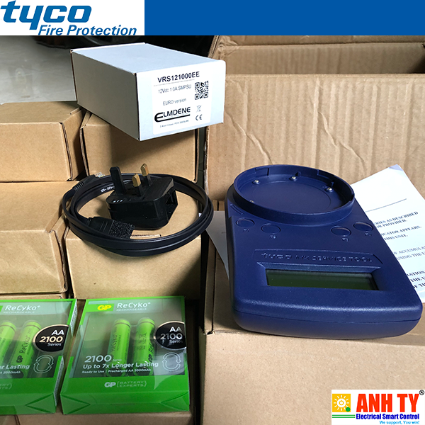
 1,644
1,644


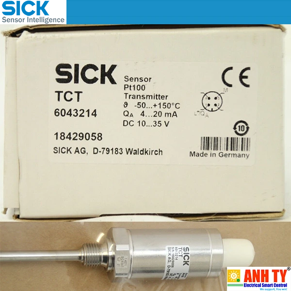 Cảm biến nhiệt độ –50...+150°C Pt100 4-20mA Sick TCT-1AAG12506MZ | 6043214Giá tốt nhất xem...0909186879 Email
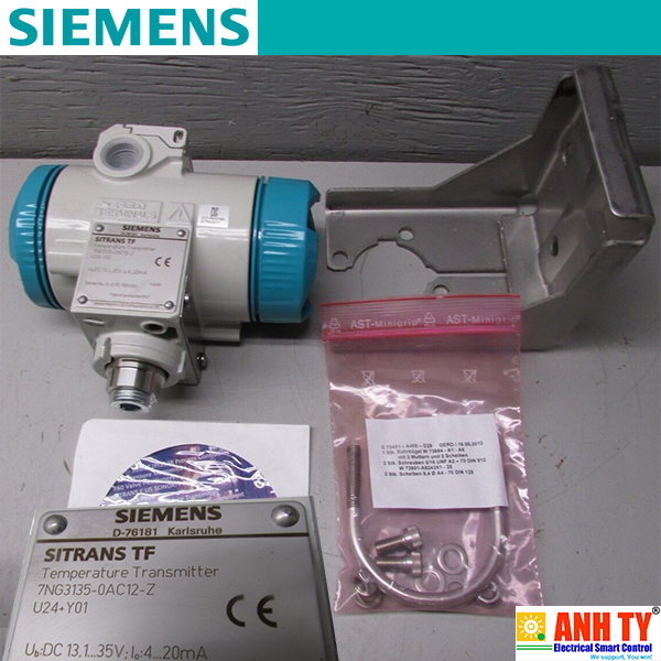 Bộ chuyển phát tín hiệu nhiệt độ Siemens 7NG3135-0AC12-ZGiá tốt nhất xem...0909186879 Email
 Mô-đun điều khiển nhiệt PIXSYS ATR244-12ABCGiá tốt nhất xem...0909186879 Email
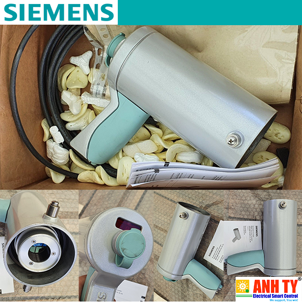 Nhiệt kế quang phổ MPA13AF1 500-1600oC Siemens 7MC3030-1AB13Giá tốt nhất xem...0909186879 Email
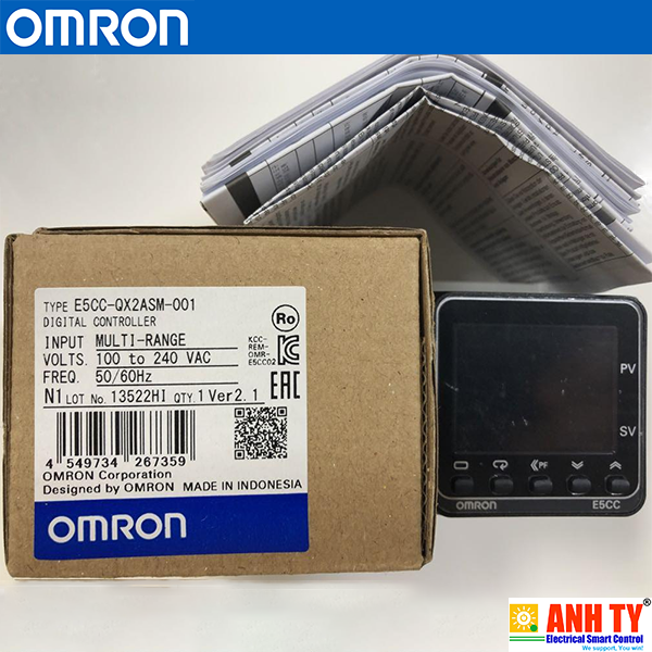 Bộ điều khiển nhiệt 48x48 100-240V 2Aux 1HS 2Eve Omron E5CC-QX2ASM-001Giá tốt nhất xem...0909186879 Email
 Thiết bị đầu báo khói-cháy quang điện - Tyco - Optical Smoke and Heat detector 851PH Model 516.850.055Giá tốt nhất Xem...0909186879 Email
 Thiết bị đầu báo cháy (nhiệt) - Tyco - 801HEx/811HExn Heat Detector Model 516.800.532Giá tốt nhất Xem...0909186879 Email
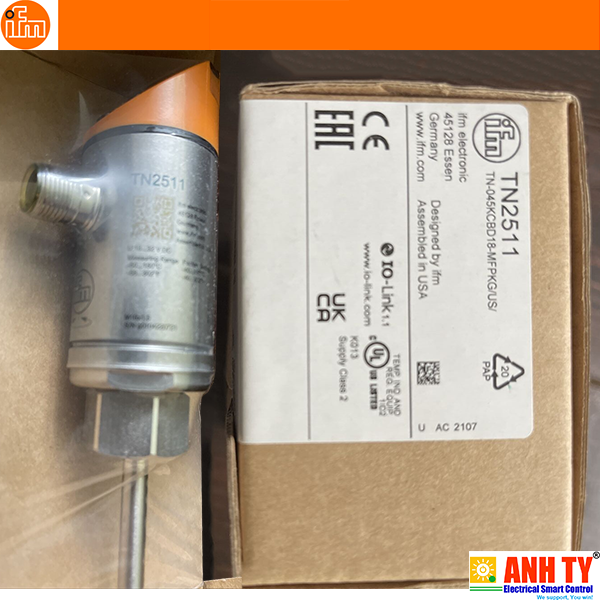 Cảm biến nhiệt độ có thông số hiển thị Temperature sensor with display - IFM - TN2511 (TN-045KCBD18-MFPKG/US/)Giá tốt nhất Xem...0909186879 Email
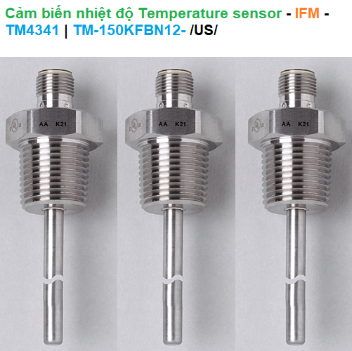 Cảm biến nhiệt độ Temperature sensor - IFM - TM4341 (TM-150KFBN12-)Giá tốt nhất Xem...0909186879 Email
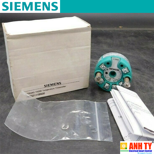 Siemens 7NG3211-1BN00 | Temperature transmitter SITRANS TH200 -Bộ chuyển phát tín hiệu nhiệt Lắp vào đầu kết nối Loại B DIN 43729 2-Wire 4-20mA Khả trình Có cách ly điện Bảo vệ nổ FM cFMUSGiá tốt nhất Xem...0909186879 Email
 West P8170-2111102R | Temperature Controller -Bộ điều khiển nhiệt độ Giá tốt nhất Xem...0909186879 Email
 Omron E52-P6DY 2M | Platinum resistance thermometers -Cảm biến nhiệt điện trở bạch kim loại PT100 3-wire −50..250°C D=6.4mm L=35mm 2mGiá tốt nhất Xem...0909186879 Email
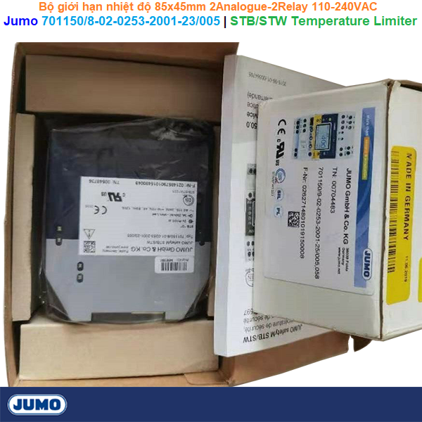 Jumo 701150/8-02-0253-2001-23/005 | STB/STW Temperature Limiter -Bộ giới hạn nhiệt độ 85x45mm 2Analogue-2Relay 110-240VACGiá tốt nhất Xem...0909186879 Email
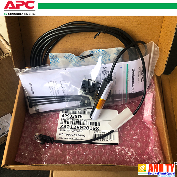 APC AP9335TH | Temperature & Humidity sensor -Cảm biến Nhiệt độ và Độ ẩm RJ45 cho Data Center or Network ClosetGiá tốt nhất Xem...0909186879 Email


