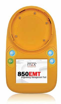
Bộ lập trình đầu báo cháy-khói cho 850 Series Tyco 850EMT MX Service Tool KIT
Features
- Simplifies installation & commissioning
- Bidirectional IR link allows remote detector programming, interrogation and testing
- Programs all MX Detectors & Ancillaries
- 320x240 QVGA Backlit TFT Touch Screen
When used with Tyco MX1 systems, the 850EMT can remotely interrogate, address and test the 850 Series detectors. Alternatively, any MX detector can plug on directly; MX modules are connected using an ancillary lead (supplied).
Bidirectional IR Link
The ability of the 850EMT to communicate with the 850 series detectors on a Tyco MX1 using a bidirectional infrared wireless link is unique. This feature allows you to better manage the commissioning and servicing of 850 Series detectors from ground level without the requirements of high ladders or cherry pickers.
Programming, testing and verification of a detector can be carried out by a single visit to the device - from the ground. This is a major benefit: saving you time, costs and the health and safety of your commissioning technicians.
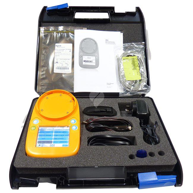
The 850EMT Kit consists of:
- 850EMT Service Tool
- 6x AA NiMH rechargeable batteries
- 240VAC mains adaptor
- 12Vdc car adaptor
- Ancillary programming lead
- Spare pins for the programming lead
- Carry case and shoulder strap.
Specifications
- Dimensions 48 x 200 x 112mm
- Weight 500g incl. batteries
- Battery 6x AA NiMH rechargeable
- Battery Life up to 15 hrs operation/charge
- Mains 240VAC to 12Vdc Adaptor
- IR Range (selectable) up to 5m / 5m to 15m
- Ambient Temperature 0°C to +50°C
- Relative Humidity 10% to 95% (non cond.)
Part Numbers
850EMTK 850EMT Service Tool Kit
516.850.904 Stylus
516.800.922 Ancillary Lead
516.800.923 Carry Case & Accessories
516.800.924 Anc. Lead Spare Pins (Pk 10)
850EMTK 850EMT Service Tool Kit
Left Side View

1 - DC IN 12V External Connector
2 - Power On/Off Switch
Right Side View
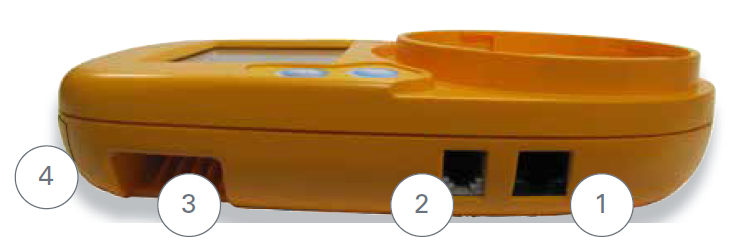
1 - AUX Cable Port
2 - COM Port
3 - Belt Strap Holder
4 - Stylus
Top View
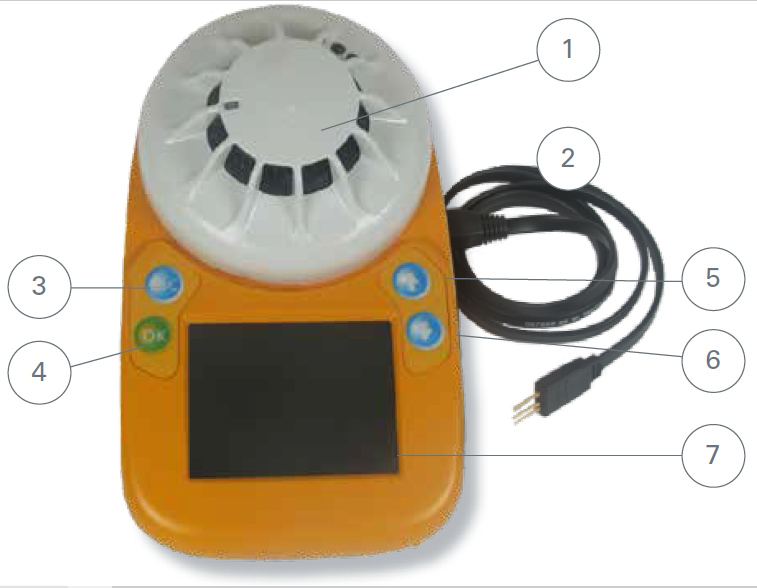
1 – Detector on Tool Base
Twist detector clockwise to engage
and lock in position
2 – Ancillary Lead
Used for programming MX devices
3 – Escape Button
4 – OK Button
5 – Up Arrow Button
6 – Down Arrow Button
7 - LCD Touch Screen
Access Information
To access all the available options, you need to log on using a standard PIN.
Once successfully logged in, there are 5 options including: DEVICE STATUS, SESSION PROGRAM, COMMUNICATION MODE, TEST FUNCTIONS, 850EMT SETTINGS.
1 Guide to this manual
1.1 Keywords and symbols
This documentation uses special notations that you can use for better orientation. Symbols in the margins indicate warnings, information or instructions. You can find an explanation of these symbols in Table 1.
1.2 Who is this Manual for?
This user manual is aimed for the Installation, Commissioning and Service Engineers in Australia and New Zealand who are using the 850EMT
1.3 What Products are
Covered by this Manual?
This manual covers the 850EMT (Engineering Management Tool) with Australia and New Zealandspecific features enabled.
This manual describes the product range and features as used in Australia and New Zealand.
For use with marine detectors, or UK-sourced MZX systems, please see manual 120.515.058.
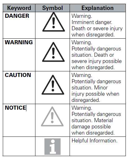
Table 1: Keywords and symbols in this manual
2 Introduction
The 850EMT Engineering Management Tool is a powerful and flexible tool used in the installation, commissioning, diagnostics and servicing of Tyco MX detection systems.
The 850EMT allows all the MX addressable devices to be interrogated, tested and programmed. Its easyto-navigate screens capture user requirements in an intuitive manner.
The 850EMTK includes the following:
- 850EMT MX Service Tool
- MX Service Tool to Ancillary connector lead
- Mains charger adaptor
- 6 x rechargeable AA size NiMH batteries
- USB Memory Stick
- Pack of ten spare pins for Ancillary lead
- Carry case
- Shoulder Strap for 850EMT
- 12V car charger adaptor.
2.1 Key Functions and Features
The 850EMT can be used as a desktop unit, clipped to a trouser belt or be carried using a shoulder strap.
The key functions and features of the 850EMT are:
- Two-way communication via infrared (IR) to 850 Series detectors and modules
- Touch screen Backlit colour LCD display
- Portable with built in charger
- Accepts detectors onto the tool or ancillary programming lead for modules
- Read/write detector / ancillary address
- Displays model number and the SKU
- Displays temperature / CO levels / smoke obscuration
- Tests the detector remote LED and control outputs
- Monitors ancillary outputs
- Reads the device status
- Changes the device settings
- Session Programming - enables programming of multiple devices in succession
- Test Functions - Allows the device’s inputs and outputs to be tested and the blink-on-poll setting to be changed
- Entry buttons have black border or red (when selected) which respond to touch
- DC IN +12 V - External connection from the car 12V socket or mains adaptor
- In-built stylus to select menu options by touching the LCD screen.
2.2 Benefits of Using 850EMT
Advantages of using the 850EMT are:
- Simplifies installation and commissioning
- Bidirectional IR link allows remote detector programming, interrogation and testing
- Improves health and safety by reducing the need to work at height
- Reduces the possibility of Engineering error.
3 Operating Instructions
3.1 Indicators and Controls
The 850EMT is shown in Figure 3. The numbered items in the figure are explained in the following paragraphs.
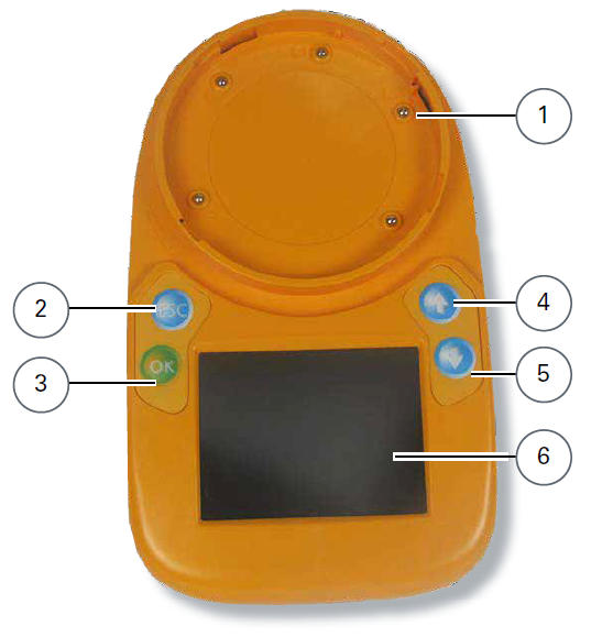
Fig. 1: 850 Engineering Management Tool
1 – Tool Base
2 – Escape Button
3 – OK Button
4 – Up Arrow Button
5 – Down Arrow Button
6 – LCD Display Screen
Tool Base
The circular area is used to fit an MX detector, by rotating the detector in the clockwise direction until it reaches the lock position. For additional details, see 4.4 “Connecting to a Detector”.
3.2 Batteries
The 850EMT is powered by 6 AA NiMH batteries located underneath a cover in the base of the unit.
How to fit/replace the batteries
1 Remove the battery compartment cover located on the base of the 850EMT (use a flat bladed screwdriver if desired).
2 Insert the NiMH AA sized batteries ensuring correct polarity as marked on the PCB, or as shown in Figure 4.
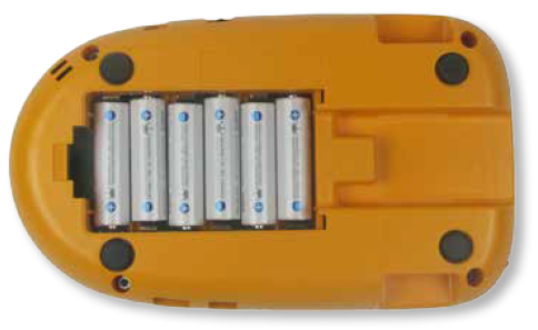
Fig. 4: Batteries placed in the battery compartment
3 Refit the battery compartment cover by gently pushing it down, hard enough such that it audibly clicks into place.
CAUTION
Battery Status:
- Fully charge the batteries for 4 hours before using for the first time
- Recharge the batteries as soon as the Low Battery indicator appears
- Do not open the battery compartment cover while the unit is switched on, or charging
- Ensure that only Tyco specified Nickel Metal Hydride rechargeable batteries are used and fully charged before use.
Charging and Mains Use
The 850EMT has its own built-in charging circuit, powered by an external adaptor.
Adaptors for mains and 12V car charging/operation are included.
Charging while the 850EMT is OFF
If the 850EMT is switched off and you connect a charging adaptor the 850EMT will automatically turn on while it is in the state of charging.
If you disconnect the adaptor to stop charging it, the 850EMT will switch off automatically.
4 Starting the 850EMT
The screen shown in Figure 5 appears for about 3 seconds after the power is turned on (refer to Figure 1 #2).

Fig. 5: 850EMT Start-up Screen
4.1 Logging On
How to log on to the 850EMT
1 In the PIN Entry screen, enter the 4-digit PIN 7240 by using the numeric keypad as shown in Figure 6 and press
Enter.
2 If the PIN is correct, the message
PIN ACCEPTED is displayed on the screen. The user will remain logged in until the 850EMT is turned off.
The PIN Entry screen is as shown in Figure 6.
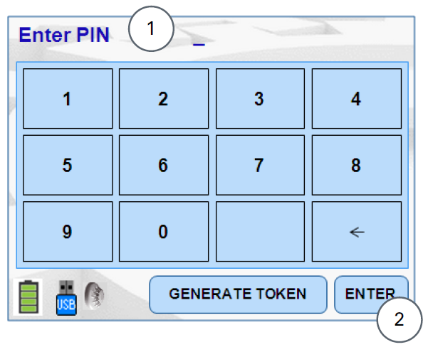
Fig. 6: PIN Entry Screen
1 - Enter PIN Field
2 - Enter key
Invalid PIN
If the PIN entered is incorrect, the message
INVALID PIN is displayed on the screen.
4.2 Main Menu Screen
After the 4-digit PIN number has been successfully entered, the main menu screen appears as shown in Figure 7. Detail on using the main menu is covered in Section 5.
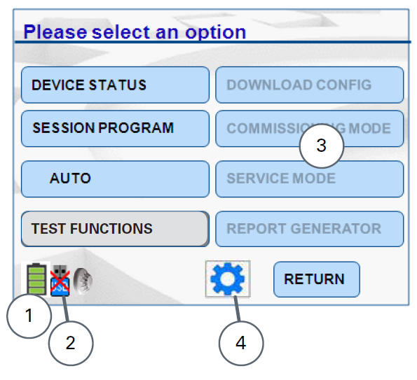
Fig. 7: Main Screen
1 – Battery Status
2 – USB Icon Indicates Disconnected
3 – Four Disabled Options
4 – 850EMT Settings Button
Each option leads to a further screen, which may present further options.
When using the menus you use combinations of the same basic methods – to navigate between the various settings in a screen for example. To avoid repetition, this guide does not provide full step by step details for every screen.
LCD Display
A 3.5 inch QVGA TFT backlit LCD alphanumeric display with a high resolution of 320 x 240 pixels and 262k colours is provided as the Graphical User Interface.
This is used to display user interaction information, such as alarms, status, messages and responses to user input.
Buttons or Icons
Buttons/Icons are used for entering access codes, text strings or general information.
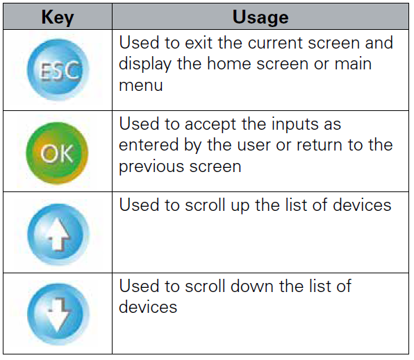
Table 2: Buttons
Battery Status
The battery icon changes its display as shown in Table 3 to indicate the different states of charging.
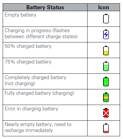
Table 3: Battery States
4.3 Connecting to an MX Device
The 850EMT can be connected to MX detectors or ancillary devices using the tool base, the Ancillary lead, or infrared communications.
The 5 different modes used by the 850EMT to communicate with the device are:
- IR High: The 850EMT communicates with the detectors placed at a distance between 1m to 15m via the infrared link. It is indicated by the icon

on the bottom left hand corner of the main screen.
- IR Low: The 850EMT communicates with the detectors placed at a distance between 0 and 5m via the infrared link. It is indicated by the icon

.
See Section 4.6 for using IR mode.
IR Link
The IR mode needs to be enabled at the fire
panel before the IR link can be used.
CAUTION
Turn off the Sounders before enabling the IR Mode, to avoid the devices from overloading the loop and from being accidentally activated by the 850EMT Address Programming Tool.
AUX Cable: Communication between the 850EMT and the ancillary is possible by attaching the auxiliary cable to the AUX socket of the 850EMT and plugging it on to the auxiliary device (3 pins). Refer to 4.5 “Connecting to an Ancillary Device” on page 13. It is indicated by the icon

on the main screen.
NOTICE
If the 850EMT is not in the Auto mode, it cannot automatically detect the Communication mode to be ‘AUX’ for legacy ancillary leads. You have to manually select ‘AUX’.
- Tool Base: Communication between the 850EMT and the device is possible by placing the detector in the lock position on the tool base of the 850EMT. Refer to 4.4 “Connecting to a Detector” on page 12. It is indicated by the icon

.
- Auto: The 850EMT automatically detects the kind of mode with which it has to communicate with the device by considering each of the following scenarios:
– If the Ancillary lead is plugged in AUX Mode is selected.
– If a detector is fixed onto the tool base, the Tool Base mode is chosen.
– If no auxiliary cable is present and the detector is not fixed onto the tool base, the 850EMT chooses IR Low as the default mode of communication.
– If the ancillary is connected to the 850EMT via the Auxiliary cable and a detector is fixed on the tool base, the 850EMT does not choose any communication mode.
In this scenario, an error message is displayed as:
Setup not allowed
Remove detector or disconnect AUX cable. It is indicated by the icon

This is due to a conflict between the AUX mode and
the Tool base modes of communication.
Auto mode - Not Available
This functionality is not applicable for:
- The 813P and the 801F/801FEx Flame detectors.
- Intrinsically Safe detectors such as the 801PHEx, 801HEx, 801CHEx etc.
These detectors can communicate with the 850EMT via only the Tool base mode of communication.
4.4 Connecting to a Detector
Detectors are connected to the 850EMT via the Toolbase as shown in Figure 8.
Use the marking on the service tool (above ESC button) to align the detector. Place the detector in position 1 to engage and then twist clockwise to position 2 to lock.
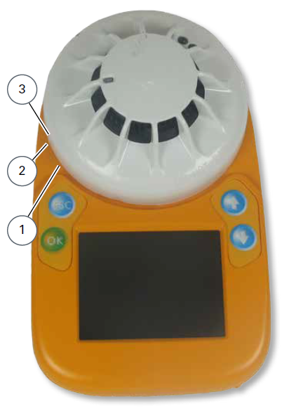
Fig. 8: Connecting to a detector
1 – Position 1
2 – Position 2
3 – Marking
4.5 Connecting to an Ancillary Device
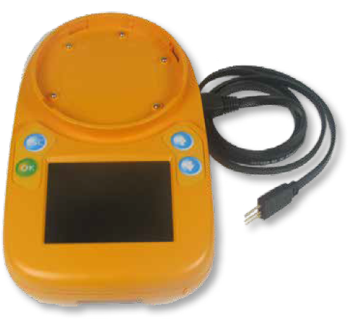
Fig. 9: Connecting to an Ancillary Device
Connecting to an Ancillary Device
Plug the 3-pin header into the matching three holes or connector on the MX device. The device can be powered off, or connected to an operational MX loop. The ancillary lead will power the device sufficiently to communicate with it and override the MX loop communications.
Available Connections
It is good practice to connect only a detector or one ancillary device at a time. The 850EMT is equipped with a port interlock feature.
When the ancillary lead is connected to the AUX socket, communication via the IR link and base connection are disabled.
When the ancillary lead is removed, the 850EMT will be able to communicate via the IR link and the tool base connection will be re-enabled.
The 850EMT may be connected to an ancillary device that is also connected to and powered from the addressable loop. However, a ‘No Response’ fault for that device may be generated at the Control Panel under these conditions.
4.6 Using IR Mode
Using Infrared Mode
Infrared communications can be used with certain MX detectors and modules that contain the IR transceiver (currently 850 Series detectors and Quad I/O modules). The devices need to be connected to and powered by the compatible MX panel and IR mode needs to be enabled on the panel before IR mode can be used. Refer to the specific Fire Panel Operator’s Manual.
With IR mode enabled, carefully point the 850EMT at the MX device until the yellow LED on the device flashes to indicate successful communications. If successful IR comms are enabled (see section 5.6) the 850EMT will beep with a specific chirp when it can successfully communicate with the device using IR.
Keep the 850EMT pointing at the device and use its screens and buttons to select the required functions.
Note that if the 850EMT no longer points directly at the device, IR communication will stop working.
5 Menu Details
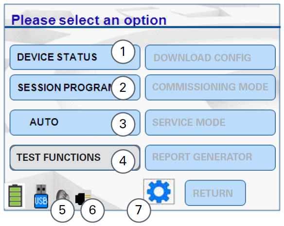
Fig. 10: Main Menu-Listed Options
1 – Device Status and Change Settings
2 – Session Program-Manual and Auto Modes
3 – Communication Mode (For this example shown as AUTO)
4 – Test Functions
5 – Detector connected to 850EMT
6 – Device connected via an Ancillary to the 850EMT
7 – Navigate to “850EMT Settings”
5.1 Main Menu Options
There are five options, as follows:
- DEVICE STATUS - used to display the previously configured device settings and allows you to change these settings as required. See 5.2 “Device Status”.
- SESSION PROGRAM - allows the user to manually/ automatically programme addresses into the device and reset the session table. See 5.4 “Session Program”.
-
COMMUNICATION MODE - pressing this changes the device communication mode between IR High, IR Low, Aux Cable, Tool Base and Auto. See 4.3 “Connection to a MX Device”.
-
TEST FUNCTIONS - used to perform additional commissioning tests on the device and alter the default settings for Visual Alarm Devices. See 5.5 “Test Functions”.
-
850EMT SETTINGS (cog wheel) - used to change the 850EMT settings. See 5.6 “850EMT Settings”.
The following sections detail the menu options.
5.2 Device Status
Use
Device Status option to display the status/ configured settings of the device connected to the 850EMT.
An example
Device Status screen is shown in Figure 11
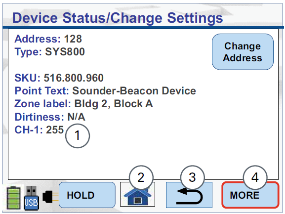
Fig. 11: Device Status & Change Settings Screen
1 – Channel analogue values
2 – Home Icon - Returns to the main screen
3 – Return Icon - Goes back to the previous screen
4 – Displaying more information
The properties shown on this screen and the More screen are as follows:
- Address: Displays the address of the device. To change the address of the device, press the
Change Address button. See Section 5.3
- Type: Displays the type of the device
- SKU: Shows the stock code of the device (for a replacement)
- Point Text: Represents the point/area where the device is located. Usually shows N/A
- Zone Label: Reflects the Zone where the device is located. Usually shows N/A
- Dirtiness: This represents the percentage of dirt or dust that is present inside the sensor, accumulated over a period of time. This field cannot be altered. The percentage value obtained may be different from the value displayed for the ‘Dirtiness’ field on the panel screen.
CAUTION
If the percentage of dirtiness is shown as 80% or above, the device may have degraded performance and should be replaced as soon as practicable.
- Obscuration: The response of an optical detector is normally measured with reference to the obscuration produced by smoke. Obscuration is measured in percent per metre. This field cannot be altered
- Temperature: The temperature for those detectors with a heat element
- CO Level: Carbon Monoxide (CO) level (ppm) for those detectors with a CO sensor
- CH-X: Channel analogue value for input X. The MX
ASIC has up to 4 analogue inputs and these are assigned different functions depending on the device type. The fields CH-1 to CH-4 show the raw analogue value (0 to 255) of the respective input. Refer to the MX device details for an explanation of each input’s function
- Node Voltage: For 850 series detectors in IR mode it is possible to read the MX loop voltage present at the detector. This value can help in fault finding or checking for voltage drops around the loop
- Mfg Date: The date of manufacture of the device
- Serial: Unique serial number of the device
- Hold: use this option to retain the values for fields (such as obscuration, dirtiness, temperature, etc.,) so that they do not fluctuate according to the environmental conditions. While in the Hold state, the 850EMT stops beeping. To return from this state, press hold again
- More: Select this option to show additional information about the device.
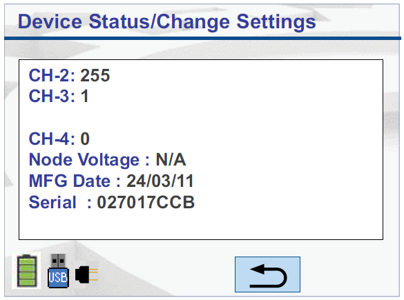
Fig. 12: Device Status More - LPSY800-R
5.3 Change Address
The Change Address function allows the address of the MX device to be changed.
Press the Change Address button to show the Change Address Screen (see Figure 13).
The
Enter Address screen appears. Type the required address (1-250) using the numeric keypad. To program the address you typed, press the
Enter button. The message
Address is changed Successfully is displayed.
In order to delete the digits typed, press the back arrow key

.
On exit, the
Device Status/Change Address screen is updated to reflect the new address.
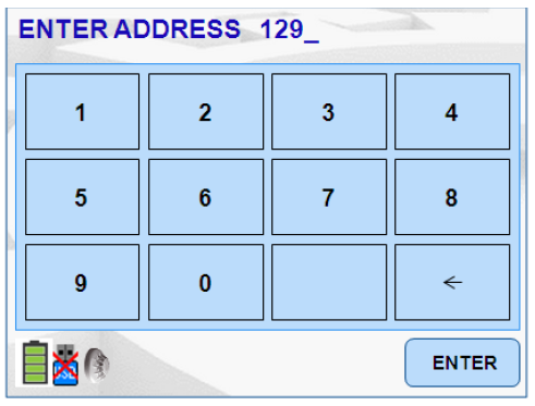
Fig. 13: Enter Address Screen
Maximum Address Value
The
Enter Address field accepts a maximum value of 255.
5.4 Session Program
Use this option to program multiple devices with consecutive addresses. The 850EMT checks a table of addresses used, so the next unused address can be assigned to each device. This session table can be cleared. From the Main menu, press the
Session Program button to display the session program screen as shown in Figure 14.
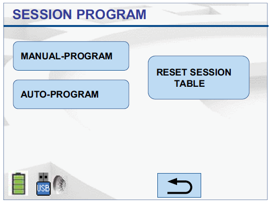
Fig. 14: Session Program
5.4.1 Manual Program
Use this option to manually navigate to the required address and select it for programming into the device. The screen appears as shown in Figure 15.
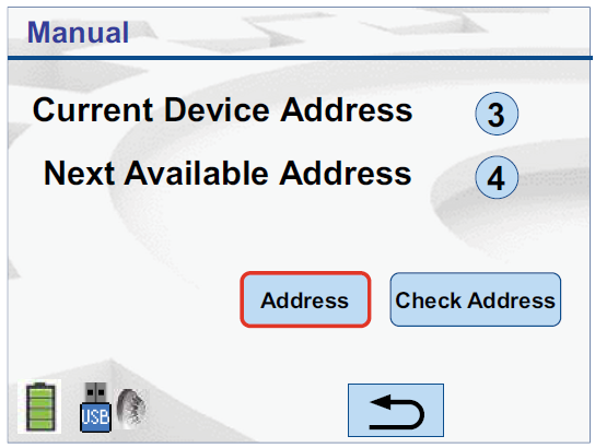
Fig. 15: Manual Session Program
To change the device’s address to the ‘Next Available Address’, press the
Address button. The message
PLEASE WAIT... PROGRAMMING DEVICE is displayed; followed by the message
Address changed successfully. To manually change the device’s address to a different address, press the
Check Address button. The
Enter Address screen appears. See section 5.3.
Type a different address and press ‘Enter’ for the 850EMT to accept and program the device.
If you attempt to program an address that has already been used by an existing device, the message appears as
ADDRESS ALREADY IN USE. In such a scenario:
- Press
Y to change the device’s address to the required address
- Press
N to retain the existing address.
5.4.2 Auto Program
Use this option to automatically program the device to the next available address. The screen appears as shown in Figure 16.
Use this option to automatically program the address of any newly fitted device with the next unused address.
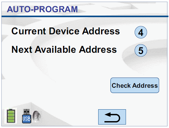
Fig. 16: Manual Session Program
To change the value of the Current Device address to a new value, click on the
Check Address button. Refer to section 5.3 for the Change Address function.
5.4.3 Reset Session Table
Use this option to reset the values displayed for the
Current Device Address and the
Next Available Address of the device. The screen appears as shown in Figure 17.
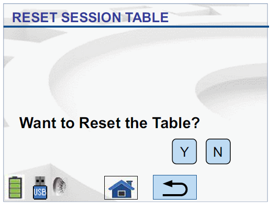
Fig. 17: Reset Table
- Press
Y to clear the used addresses table and make all addresses available. The message
Session Table has been Reset appears
- Press
N to continue with the currently displayed values. It leads you to the
Session Program screen as shown in Figure 14.
5.5 Test Functions
A number of test functions are available for MX devices from the
Test Functions menu as shown in Figure 18 which can entered from the main screen.
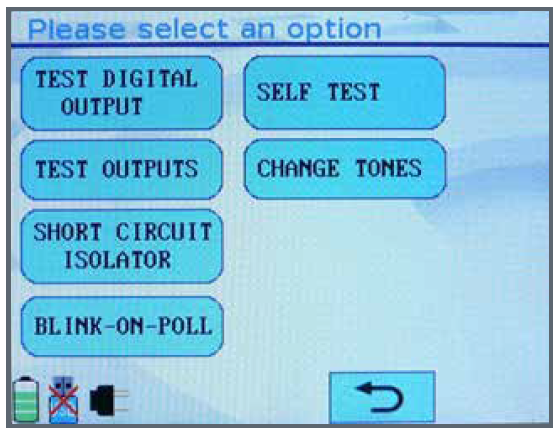
Fig. 18: Test Functions Menu
Some functions may be greyed out and unavailable depending on the MX device (if any) that is connected.
The operation of each test function is detailed in the following sections of this manual.
5.5.1 Test Digital Outputs
The Test Digital Outputs function allows the digital output signals of the MX integrated circuit to be controlled. As this function controls the actual ASIC outputs, knowledge of each output’s function on the specific MX device is required. Currently the only field application for this is configuring AZM800 modules in New Zealand. This procedure is documented in LT0459: AZM800 Installation and Setup Instructions.
The screen which is displayed on the 850EMT is shown in Figure 19. To toggle a bit between
0 and
1 (or viceversa) press that bit on the touch screen. When the bit pattern displayed on screen matches what is required, press the
WRITE button to send the digital output pattern to the MX device.
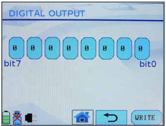
Fig. 19: Test Digital Outputs Screen
5.5.2 Test Outputs
This function allows the Remote LED and L2 (functional base) outputs of detectors to be tested. Note this function will fail on MX ancillaries.
If the device is on the MX loop and connected via the IR mode, the Test Outputs screen appears as shown in Figure 20.
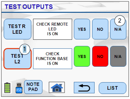
Fig. 20: Test Outputs-IR
1 – Selected option is momentarily highlighted
2 – Not Applicable option turns the function to Off
Press the
Test R LED or
Test L2 buttons to activate the output and then
YES or
NO to indicate if the output is turned on.
To stop the test function press
YES,
NO, or
N/A as shown in Figure 20. The highlighting of the result selected is only visual and is not recorded.
Fig. 21: Test Outputs-Toolbase
NOTICE
In the above screen, the Function base remains in the ‘ON’ state until all the available tests for the
TEST L2 have been completed. It is advisable to turn ‘OFF’ the F
unction base test before continuing with other tests.
If the device is connected via the tool base, the Test Outputs screen is displayed as shown in Figure 21.
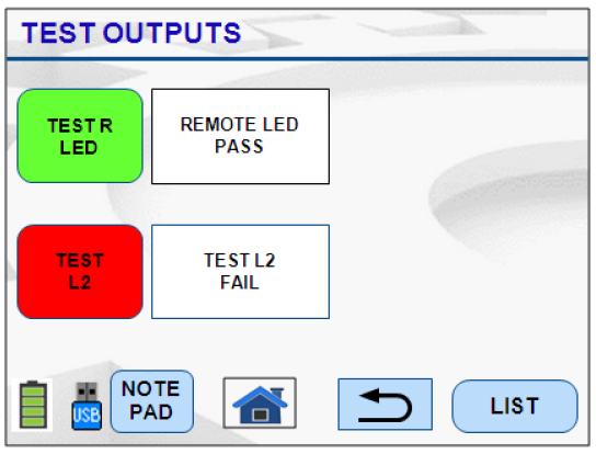
Fig. 21: Test Outputs-Toolbase
Press the required Test button and check the result on the screen.
After all the tests have been performed on the device when connected to the Toolbase, the output of the test is either of the below options:
- Pass: Result of the test is positive (Yes) and is shown
in Green
- Fail: Result of the test is negative (No) and is shown in Red.
5.5.3 Short-Circuit Isolator
Short-Circuit Isolator
This option works for only the 850 Series Generation 6 detectors and range of Quad modules.
This option is used to activate and test the isolator function of a 850 Series detector or MX Quad module.
It can be used to isolate a particular section of the loop because some planned activity requires that section to be without power. Use the
Short Circuit Isolator (SCI) function at two devices when you would like to disable the loop between those two devices.
The device’s LED is illuminated yellow to indicate that the isolator is tripped. This status remains until the isolator is closed.
Activate the Isolator
While activating an isolator when there is another open circuit fault on the loop, all the other loop devices between those two nodes will lose power.
Some loop devices may lose power if an isolator is opened and the IR mode is enabled; however, the isolator that is opened remains operational.
When the Short Circuit Isolator function is selected the screen as shown in Figure 22 appears.
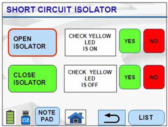
Fig. 22: Short Circuit Isolator
Pressing OPEN ISOLATOR will open the MX device’s isolator and break the loop, the yellow LED will become lit.
Pressing
CLOSE ISOLATOR will close the MX device’s isolator and close the loop, the yellow LED will not be lit.
Any result buttons pressed will be visually highlighted on screen, but no results will be recorded at all.
5.5.4 Blink-On-Poll
The blink-on-poll setting for a MX device can be changed using the Blink-On-Poll screen shown in Figure 23. To change the setting press
YES or
NO on the touch screen.
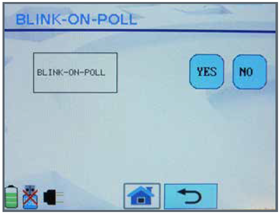
Fig. 23: Blink-On-Poll Screen
When the setting is
NO the MX device will not blink its LED when polled even when the panel is configured to enable blink-on-poll for the MX loop to which the MX device is connected.
5.5.5 Self Test
Entering the
SELF TEST function performs a self test of the supported sensors of a detector.
Initially
PLEASE WAIT… will show on screen, then the results will appear as shown in Figure 24. The overall result of the self test across all supported sensors will be shown at the bottom of the screen – in this case,
PASSED.
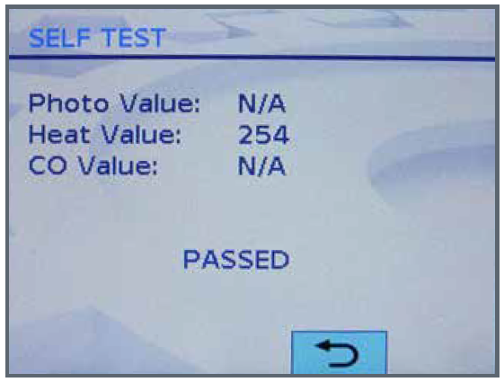
Fig. 24: Self-Test Results Screen
For sensors that aren’t present in the MX device or don’t support self test,
N/A will be shown as the value for that sensor. Many detectors support self test on only one of their sensors, and some don’t support self test on any sensors at all.
5.5.6 Change Tones
This function is for changing the tones and beacon settings for the MX Symphoni sounders and AVBase devices. The function will be greyed out on the Test Functions menu unless a supported MX device is connected.
On the main change tones screen that appears as shown in Figure 25,
1Hz and
½ Hz options are for changing the flash rate of the built-in beacon.
VOL LOW and
VOL HIGH change the volume of the tone.
RESET will reset the settings back to the factory default. The current settings are highlighted in green.
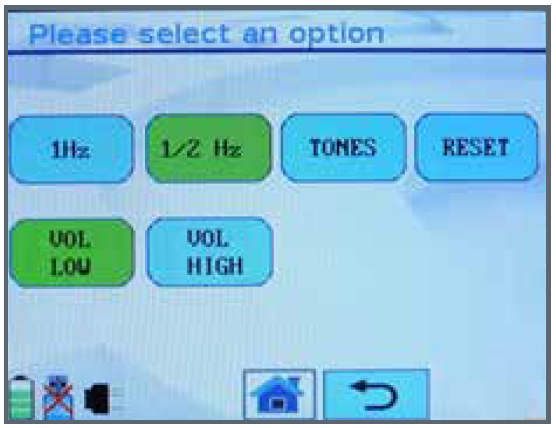
Fig. 25: Main Change Tones Screen
Pressing
TONES will bring up another screen shown in Figure 26 that allows the particular tone type to be selected.
Temp 3 (Temporal 3) is the standards compliant tone for Australia.
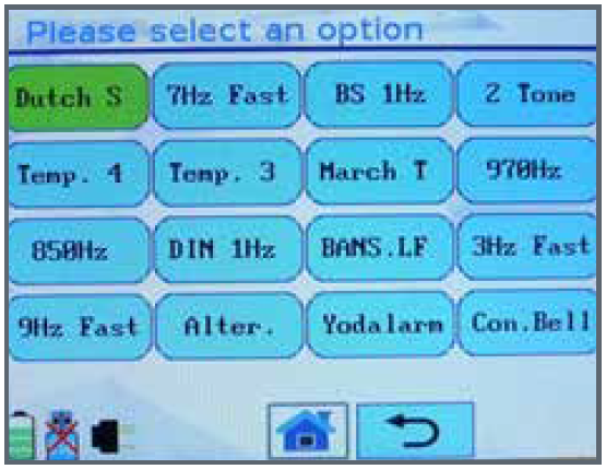
Fig. 26: Tone Selection Screen
5.6 850EMT Settings
Press the

icon on the Main Screen to navigate to the 850EMT Settings screen as shown in Figure 27.
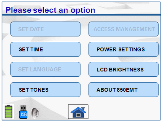
Fig. 27: 850EMT Settings
- Set Date: This option is disabled
- Set Time: Press this option to set the time or change the currently displayed time to an acceptable format.
The following screen appears as shown in Figure 28.
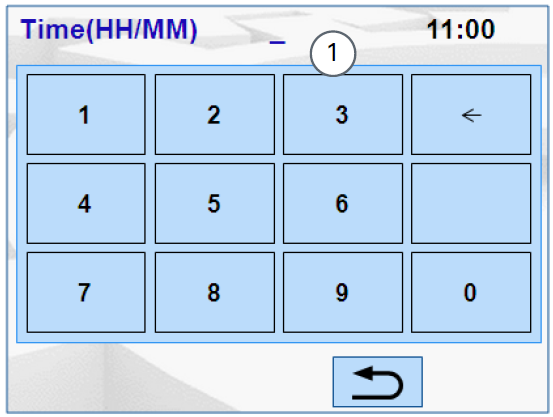
Fig. 28: Set Time
1 - Field to enter time
– Use the numeric keypad to enter the time in the format hours/minutes.
- Set Language: This option is disabled
- Set Tones: To set audible indications for touch screen operation and successful IR communications.
Press this button, the following screen appears as shown in Figure 29.
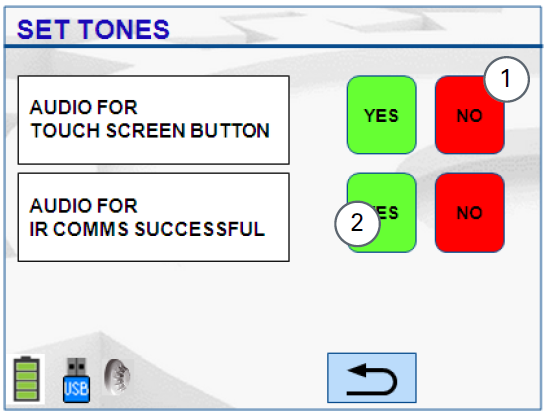
Fig. 29: Set Tones
1 – Negative option is highlighted in red.
2 – Positive options is highlighted in green.
– When you select the options by pressing it on the Main menu screen, a tone emanates from the 850EMT. To enable/disable this tone, select Yes/ No respectively.
– When the 850EMT successfully communicates with the detector via the IR Mode, a tone emanates from it. To enable/disable this tone, select Yes/No respectively.
- Access Management: This function is disabled
- Power Settings: Use this option to find out the status of the Real Time Clock (RTC) battery and the Main battery.
Press this tab, the following screen appears as shown in Figure 30.
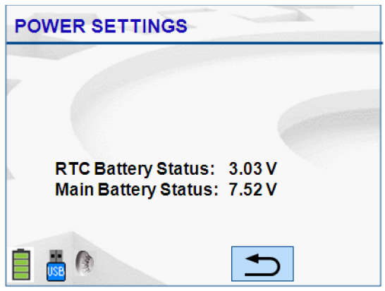
Fig. 30: Power Settings
- LCD Brightness: Use this option to increase or decrease the clarity of the LCD display screen. Press this tab, the following screen appears as shown in Figure 31.
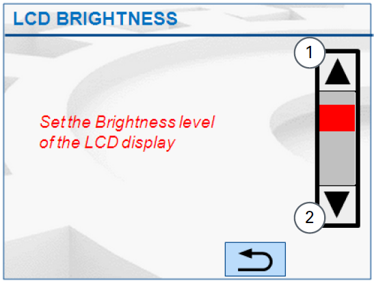
Fig. 31: LCD Brightness
1 – Scroll Up arrow to increase the brightness
2 – Scroll Down arrow to decrease the brightness
– Slide the red indicator or press the up or down
arrows to adjust the visibility of the LCD display
screen as required.
- About 850EMT: Use this option to find out the model
number and the software version of the service tool.
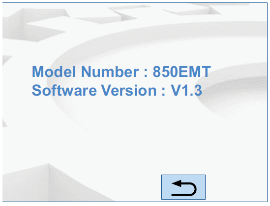
Fig. 32: About 850EMT
5.7 Ordering Information
Part:
850EMT Service Tool Kit including carry case
Order Number:
850EMTK
5.7.1 Spares
| Accessories |
Order Number |
| Spare USB Key |
516.850.902 |
| Spare Marine Download Lead |
516.850.903 |
| Stylus |
516.850.904 |
| Spare Ancillary Lead |
516.800.922 |
| Carry Case and Accessories |
516.800.923 |
| Ancillary Lead Spare Pins (bag 0f 10) |
516.800.924 |
Table 5: Order Numbers
5.7.2 Specifications
| Mechanical |
|
| Dimensions |
50 x 210 x 125 mm |
| Weight |
600 g incl. batteries |
| Electrical |
|
| Battery |
6x AA NiMH rechargeable |
| Mains |
240VAC to 12Vdc Adaptor |
| Environmental |
|
| Ambient Temperature |
0°C to +50°C |
| Relative Humidity |
10% to 95% (non cond.) |
Table 6: Specifications
6 Appendix
6.1 Additional Information
6.1.1 Compatibility
The 850EMT supports USB 2.0. The 850EMT is not compatible with all USB memory sticks. It is known to be compatible with the following memory sticks:
- Freecom Traveller (supplied with this tool)
- Kingston Data Traveller
- Lexar FireFly
The 850EMT may not work properly with USB card readers.
The 850EMT’s IR link is compatible with the 850,
4098-625X series detectors and the Quad 850 ancillaries.
The MX1 panel needs V1.5 firmware or later for IR
functionality to be available.
6.1.2 Known Issues
- There is no auto-power off or standby function.
- For USB compatibility, see 6.1.1 “Compatibility”section.
- For the 850 detectors, the SCI (Short Circuit Isolator) and the Test outputs are triggered by the same command.
6.2 Updating the Firmware
New versions of firmware can be downloaded by placing the file on the USB memory stick, placing the stick into the USB socket of the tool, and turning off/on the tool. Errors in this process will not damage the tool. The file is a .GZ type. It must not be uncompressed before use.
Consequently, the existing firmware version is replaced with the new version. The status message is displayed as Updating firmware for a few seconds.
Firmware Upload
The PIN will not be reset when new firmware is uploaded, such that access is continued and re-registration is not required.
Any saved changes made to the settings of the 850EMT automatically apply to the updated firmware.
- Xem chi tiết Hướng dẫn xử dụng/ Manual user Tyco 850EMT MX
ở đây.


 dienelectrics@gmail.com
 0909186879
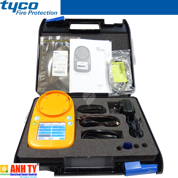
 3,083
3,083


 Thiết bị đầu báo khói-cháy quang điện - Tyco - Optical Smoke and Heat detectorGiá tốt nhất xem...0909186879 Email
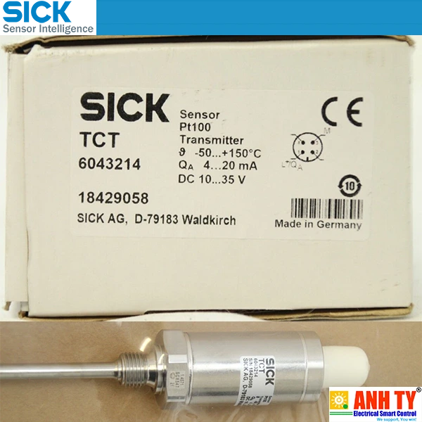 Cảm biến nhiệt độ -50...+150°C Pt100 4-20mA Sick TCT-1AAG12506MZ | 6043214Giá tốt nhất xem...0909186879 Email
 Cảm biến nhiệt độ -50...+150°C Pt100 4-20mA Sick TCT-1PAG10253MZ | 6043164Giá tốt nhất xem...0909186879 Email
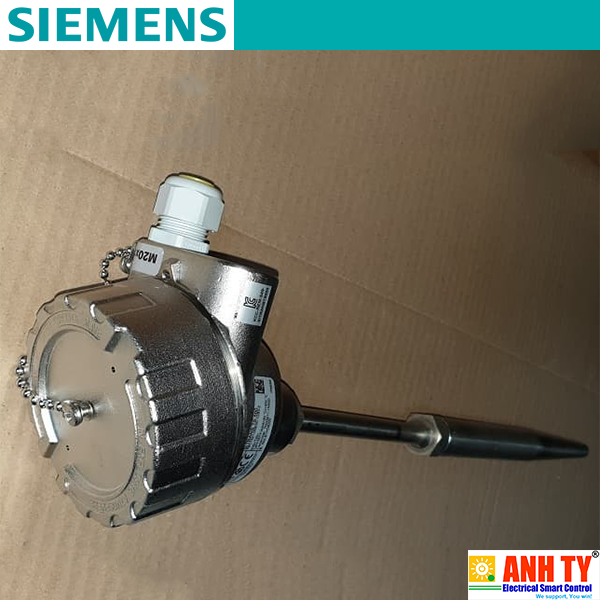 Cảm biến nhiệt độ Siemens 7MC7521-0NE00-1UB3-Z A02 C11 E00 T20 Y01Giá tốt nhất xem...0909186879 Email
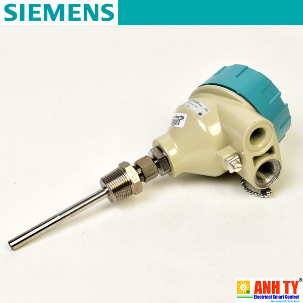 Cảm biến nhiệt độ Siemens 7MC7512-1CB25-9AK1-Z E00+N1DGiá tốt nhất xem...0909186879 Email
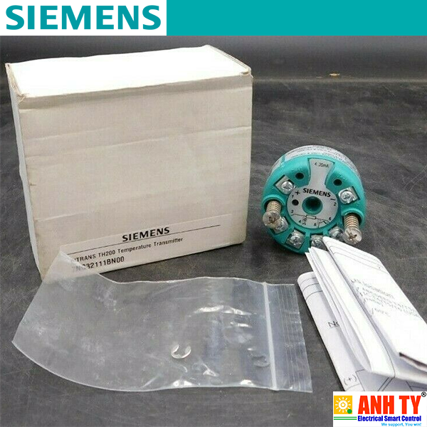 Siemens 7NG3211-1BN00 | Temperature transmitter SITRANS TH200 -Bộ chuyển phát tín hiệu nhiệt Lắp vào đầu kết nối Loại B DIN 43729 2-Wire 4-20mA Khả trình Có cách ly điện Bảo vệ nổ FM cFMUSGiá tốt nhất Xem...0909186879 Email
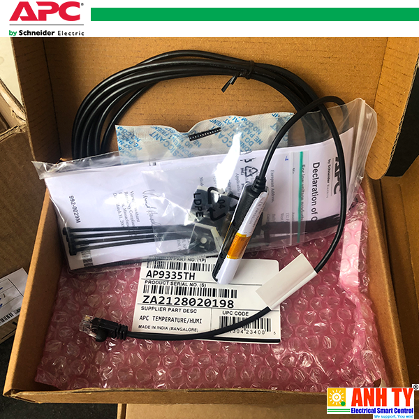 APC AP9335TH | Temperature & Humidity sensor -Cảm biến Nhiệt độ và Độ ẩm RJ45 cho Data Center or Network ClosetGiá tốt nhất Xem...0909186879 Email
 Thiết bị đầu báo cháy (nhiệt) - Tyco - 801HEx/811HExn Heat Detector Model 516.800.532Giá tốt nhất Xem...0909186879 Email
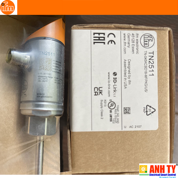 Cảm biến nhiệt độ có thông số hiển thị Temperature sensor with display - IFM - TN2511 (TN-045KCBD18-MFPKG/US/)Giá tốt nhất Xem...0909186879 Email
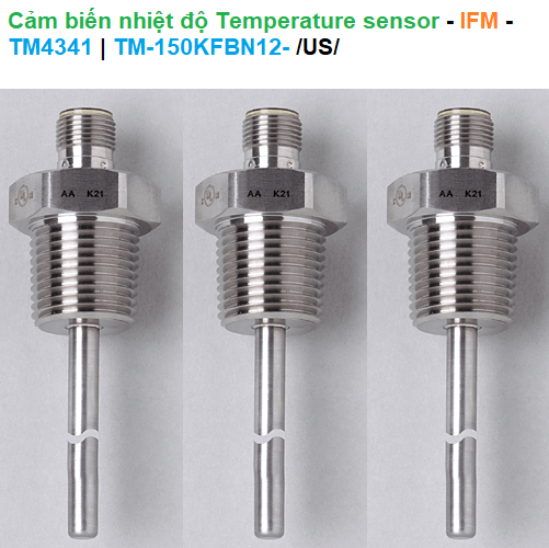 Cảm biến nhiệt độ Temperature sensor - IFM - TM4341 (TM-150KFBN12-)Giá tốt nhất Xem...0909186879 Email
 West P8170-2111102R | Temperature Controller -Bộ điều khiển nhiệt độ Giá tốt nhất Xem...0909186879 Email
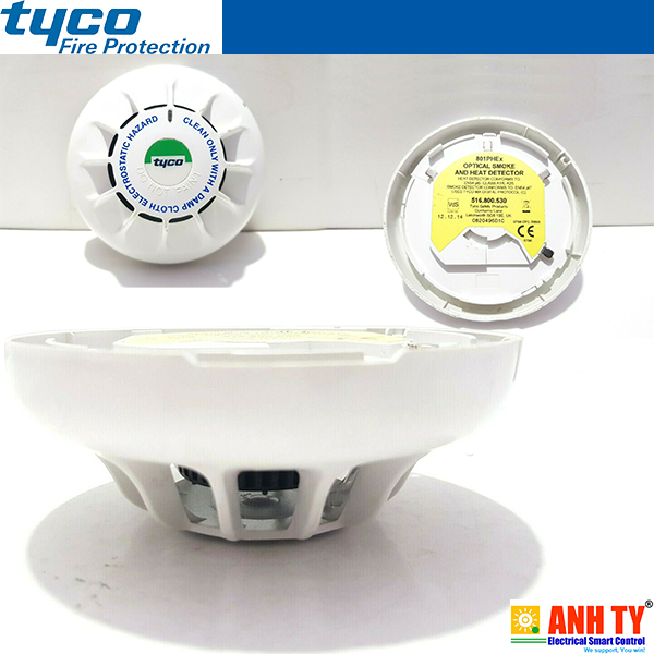 Tyco 801PHex (516.800.530) | Optical smoke heat detector -Đầu báo khói-cháy quang đa năngGiá tốt nhất Xem...0909186879 Email


