
| Utilization restriction | EMC: class A product, see manufacturer's declaration in the download area |
| Width | 6.2 mm |
| Height | 110.5 mm |
| Depth | 120.5 mm |
| Ambient temperature (operation) | -40 °C ... 70 °C |
| Ambient temperature (storage/transport) | -40 °C ... 85 °C |
| Number of inputs | 1 |
| Configurable/programmable | Yes |
| Voltage input signal | 0 V ... 10 V (via DIP switch) |
| 2 V ... 10 V (via DIP switch) | |
| 0 V ... 5 V (via DIP switch) | |
| 1 V ... 5 V (via DIP switch) | |
| 0 V ... 12 V (can be set via software) | |
| Current input signal | 0 mA ... 20 mA (via DIP switch) |
| 4 mA ... 20 mA (via DIP switch) | |
| 0 mA ... 10 mA (via DIP switch) | |
| 20 mA ... 0 mA (via DIP switch) | |
| 0 mA ... 24 mA (can be set via software) | |
| max. input voltage | 12 V |
| Max. input current | 24 mA |
| Input resistance of voltage input | > 120 kΩ |
| Input resistance current input | approx. 50 Ω (+ 0.7 V for test diode) |
| Number of outputs | 2 |
| Voltage output signal | 0 V ... 10 V (via DIP switch) |
| 2 V ... 10 V (via DIP switch) | |
| 0 V ... 5 V (via DIP switch) | |
| 1 V ... 5 V (via DIP switch) | |
| 0 V ... 10.5 V (can be set via software) | |
| Current output signal | 0 mA ... 20 mA (via DIP switch) |
| 4 mA ... 20 mA (via DIP switch) | |
| 0 mA ... 10 mA (via DIP switch) | |
| 20 mA ... 0 mA (via DIP switch) | |
| 0 mA ... 21 mA (can be set via software) | |
| Max. output voltage | approx. 12.3 V |
| Max. output current | 24.6 mA |
| Short-circuit current | ≤ 25 mA |
| Load/output load voltage output | ≥ 10 kΩ |
| Load/output load current output | ≤ 600 Ω (per channel) |
| Ripple | < 20 mVPP (at 600 Ω) |
| < 20 mVPP (at 600 Ω) |
| Nominal supply voltage | 24 V DC |
| Supply voltage range | 9.6 V DC ... 30 V DC (The DIN rail bus connector (ME 6,2 TBUS-2 1,5/5-ST-3,81 GN, Order No. 2869728) can be used to bridge the supply voltage. It can be snapped onto a 35 mm DIN rail according to EN 60715)) |
| Typical current consumption | 55 mA (24 V DC) |
| 110 mA (12 V DC) | |
| Power consumption | ≤ 1.5 W (at IOUT = 20 mA, 9.6 V DC, 600 Ω load) |
| Connection method | Screw connection |
| Single conductor/terminal point, solid, with ferrule, min. | 0.2 mm² |
| Single conductor/terminal point, solid, with ferrule, max. | 1.5 mm² |
| Single conductor/terminal point, solid, without ferrule, min. | 0.2 mm² |
| Single conductor/terminal point, solid, without ferrule, max. | 2.5 mm² |
| Conductor cross section flexible min. | 0.2 mm² |
| Conductor cross section flexible max. | 1.5 mm² |
| Min. AWG conductor cross section, flexible | 24 |
| Max. AWG conductor cross section, flexible | 12 |
| Stripping length | 10 mm |
| Screw thread | M3 |
| No. of channels | 2 |
| Maximum transmission error | 0.05 % (of final value) |
| Maximum temperature coefficient | 0.01 %/K |
| Step response (10-90%) | approx. 140 ms (15 Hz sample rate) |
| approx. 45 ms (60 Hz sample rate) | |
| approx. 25 ms (240 Hz sample rate) | |
| Electrical isolation | Reinforced insulation in accordance with IEC 61010-1 |
| Overvoltage category | II |
| Degree of pollution | 2 |
| Rated insulation voltage | 300 V |
| Test voltage, input/output/supply | 3 kV (50 Hz, 1 min.) |
| Electromagnetic compatibility | Conformance with EMC directive |
| Noise emission | EN 61000-6-4 |
| Noise immunity | EN 61000-6-2 When being exposed to interference, there may be minimal deviations. |
| Color | gray |
| Housing material | PBT |
| Mounting position | any |
| Assembly instructions | The T connector can be used to bridge the supply voltage. It can be snapped onto a 35 mm DIN rail according to EN 60715. |
| Conformance | CE-compliant |
| ATEX | II 3 G Ex nA IIC T4 Gc X |
| UL, USA/Canada | UL 508 Listed |
| Class I, Div. 2, Groups A, B, C, D T6 | |
| Class I, Zone 2, Group IIC T6 | |
| GL | GL applied for |
| Fire protection for rail vehicles (DIN EN 45545-2) R22 | HL 1 - HL 2 |
| Fire protection for rail vehicles (DIN EN 45545-2) R23 | HL 1 - HL 2 |
| Fire protection for rail vehicles (DIN EN 45545-2) R24 | HL 1 - HL 2 |
| Designation | Electromagnetic RF field |
| Standards/regulations | EN 61000-4-3 |
| Typical deviation from the measuring range final value | 0.2 % |
| Designation | Fast transients (burst) |
| Standards/regulations | EN 61000-4-4 |
| Typical deviation from the measuring range final value | 0.1 % |
| Designation | Conducted interferences |
| Standards/regulations | EN 61000-4-6 |
| Typical deviation from the measuring range final value | 2.8 % |
| Electromagnetic compatibility | Conformance with EMC directive |
| Noise emission | EN 61000-6-4 |
| Standards/regulations | EN 61000-4-2 |
| Designation | Electromagnetic RF field |
| Standards/regulations | EN 61000-4-3 |
| EN 61000-4-4 | |
| EN 61000-4-5 | |
| Designation | Conducted interferences |
| Standards/regulations | EN 61000-4-6 |
| Electrical isolation | Reinforced insulation in accordance with IEC 61010-1 |
| Conformance | CE-compliant |
| ATEX | II 3 G Ex nA IIC T4 Gc X |
| UL, USA/Canada | UL 508 Listed |
| Class I, Div. 2, Groups A, B, C, D T6 | |
| Class I, Zone 2, Group IIC T6 | |
| GL | GL applied for |
| Fire protection for rail vehicles (DIN EN 45545-2) R22 | HL 1 - HL 2 HL 1 - HL 2 HL 1 - HL 2 |
| Fire protection for rail vehicles (DIN EN 45545-2) R23 | HL 1 - HL 2 HL 1 - HL 2 HL 1 - HL 2 |
| Fire protection for rail vehicles (DIN EN 45545-2) R24 | HL 1 - HL 2 HL 1 - HL 2 HL 1 - HL 2 |
| Fire protection for rail vehicles (DIN EN 45545-2) R26 | HL 1 - HL 2 HL 1 - HL 2 HL 1 - HL 2 |
| China RoHS | Environmentally Friendly Use Period = 50 |
| For details about hazardous substances go to tab “Downloads”, Category “Manufacturer's declaration” |
| eCl@ss 4.0 | 27210120 |
| eCl@ss 4.1 | 27210120 |
| eCl@ss 5.0 | 27210120 |
| eCl@ss 5.1 | 27210120 |
| eCl@ss 6.0 | 27210120 |
| eCl@ss 7.0 | 27210120 |
| eCl@ss 8.0 | 27210120 |
| eCl@ss 9.0 | 27210120 |
| ETIM 4.0 | EC002653 |
| ETIM 5.0 | EC002653 |
| ETIM 6.0 | EC002653 |
| UNSPSC 6.01 | 30211506 |
| UNSPSC 7.0901 | 39121008 |
| UNSPSC 11 | 39121008 |
| UNSPSC 12.01 | 39121008 |
| UNSPSC 13.2 | 39121008 |
 Màn hình digital hiển thị tín hiệu Phoenix Contact MCR-SL-D-U-I - 2864011Giá tốt nhất xem...0909186879 Email
 Bộ định áp Phoenix Contact MINI MCR-SL-CVS-24-5-10-NC - 2902822Giá tốt nhất xem...0909186879 Email
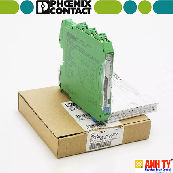 Bộ khuếch đại chuyển mạch cách ly Phoenix Contact MACX MCR-EX-SL-NAM-2RO -Giá tốt nhất xem...0909186879 Email
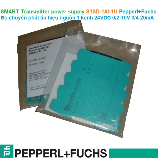 Bộ chuyển phát tín hiệu nguồn Pepperl+Fuchs S1SD-1AI-1U | 24VDC 0/2-10V 0/4-20mAGiá tốt nhất xem...0909186879 Email
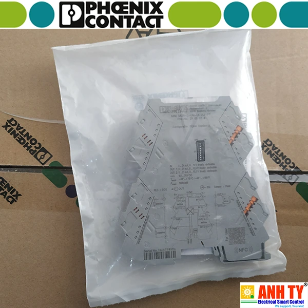 Bộ chuyển đổi tín hiệu điện trở nhiệt Phoenix Contact MINI MCR-2-RTD-UI-C -Giá tốt nhất xem...0909186879 Email
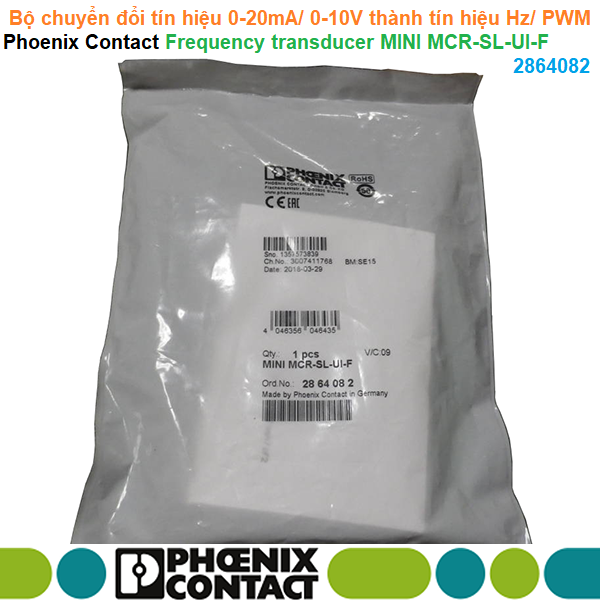 Bộ chuyển đổi tín hiệu 0-20mA/ 0-10V thành tín hiệu Hz hoặc PWM - Phoenix Contact - Frequency transducer MINI MCR-SL-UI-F 2864082Giá tốt nhất Xem...0909186879 Email
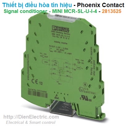 Bộ chuyển đổi tín hiệu V-A Phoenix Contact MINI MCR-SL-U-I-4 - 2813525Giá tốt nhất Xem...0909186879 Email
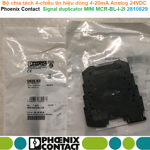 Bộ chia tách 4-chiều tín hiệu dòng 4-20mA Analog 24VDC - Phoenix Contact - Signal duplicator MINI MCR-BL-I-2I - 2810829Giá tốt nhất Xem...0909186879 Email
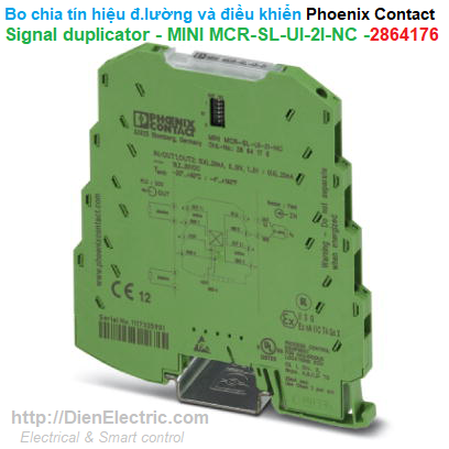 Bộ chia tín hiệu đo lường và điều khiển - Phoenix Contact - Signal duplicator - MINI MCR-SL-UI-2I-NC - 2864176Giá tốt nhất Xem...0909186879 Email
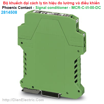 Bộ khuếch đại cách ly tín hiệu đo lường và điều khiển - Phoenix Contact - Signal conditioner - MCR-C-I/I-00-DC - 2814508Giá tốt nhất Xem...0909186879 Email
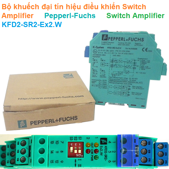 Bộ khuếch đại tín hiệu Switch Amplifier - Pepperl-Fuchs - Switch Amplifier KFD2-SR2-Ex2.WGiá tốt nhất Xem...0909186879 Email
 Bộ chia khuếch đại tín hiệu Phoenix Contact MINI MCR-2-UNI-UI-2UI-C - 2905025Giá tốt nhất Xem...0909186879 Email
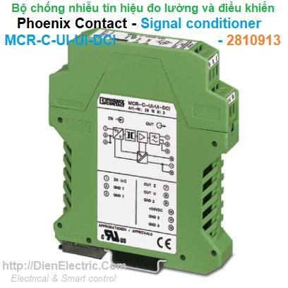 Bộ chống nhiễu tín hiệu đo lường và điều khiển - Phoenix Contact - Signal conditioner - MCR-C-UI-UI-DCI - 2810913Giá tốt nhất Xem...0909186879 Email
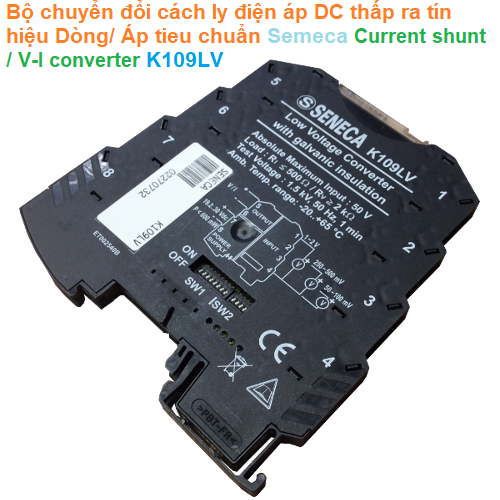 Bộ chuyển đổi cách ly điện mV ra tín hiệu Dòng/ Áp DC chuẩn - Seneca - Current shunt / V-I converter K109LVGiá tốt nhất Xem...0909186879 Email