
 |
| General specifications | ||
|---|---|---|
| Signal type | Analog input | |
| Supply | ||
| Connection | Power Rail or terminals 14+, 15- | |
| Rated voltage | 19 ... 35 V DC | |
| Ripple | within the supply tolerance | |
| Power dissipation | 0.8 W | |
| Power consumption | 0.8 W | |
| Interface | ||
| Programming interface | programming socket | |
| Input | ||
| Connection side | field side | |
| Connection | terminals 1, 2, 3, 4, 5, 6 | |
| RTD or resistance | type Pt100 (EN 60751: 1995) type Ni100 (DIN 43760) 0 ... 500 Ω (including lead resistance) |
|
| Measuring current | approx. 400 µA with RTD | |
| Lead resistance | max. 50 Ω per line | |
| Thermocouples | type B, E, J, K, N, R, S, T (IEC 584-1: 1995) type L (DIN 43710: 1985) |
|
| Voltage | 0 ... 10 V , 2 ... 10 V | |
| Current | 0 ... 20 mA , 4 ... 20 mA | |
| Load | 20 Ω for 20 mA; 200 kΩ for 10 V | |
| Output | ||
| Connection side | control side | |
| Connection | output I: terminals 7, 8, 9; output II: terminals 10, 11, 12 | |
| Output I, II | relay | |
| Contact loading | 253 V AC/2 A/500 VA/cos φ min. 0.7; 40 V DC/2 A resistive load | |
| Mechanical life | 2 x 10⁷ switching cycles | |
| Transfer characteristics | ||
| Resolution | temperature: 0.0625 °C, resistance: 62.5 mΩ, voltage: 62.5 µV, current: 625 nA | |
| Deviation | ||
| Voltage input | ± 0.02 % of 10 V measuring range | |
| Resistance input | ± 0.025 % of measuring range (4-wire connection) | |
| Current input | ± 0.02 % of 20 mA measuring range | |
| Pt100 | ± 0.01 % of abs. temperature value of switching point in K + 0.2 K (4-wire connection) | |
| Thermocouple | ± 0.05 % of abs. temperature value of switching point in K + 1.1 K (1.2 K for thermocouple types R and S) this includes ± 0.8 K fault of the cold junction compensation (CJC) (+0.9 K for thermocouple types R and S). Note! Because the sensitivity of thermocouples is, in general, lower at low temperatures than at high temperatures, the specified accuracy figures cannot be guaranteed when measuring temperatures below those listed here. -50 °C (type E and K thermocouples) -100 °C (type J, L and T thermocouples) +500 °C (type B thermocouple) |
|
| Influence of ambient temperature | ||
| Pt100 | ± (0.0015 % of abs. temperature value of switching point in K + 0.01 K)/K ΔTamb*) | |
| Thermocouple | ± (0.004 % of abs. temperature value of switching point in K + 0.01 K) / KΔTamb*) | |
| Voltage input | ± (0.007 % of the switching point voltage) / KΔTamb*) | |
| Current input | ± (0.004 % of the switching point current)/KΔTamb*) *) ΔTamb = ambient temperature change referenced to 23 °C (296 K) |
|
| Influence of supply voltage | < 0.001 % of sensor input range | |
| Input delay | ≤ 370 ms (rise time and energizing delay of relay) | |
| Galvanic isolation | ||
| Output/power supply | reinforced insulation according to IEC/EN 61010-1, rated insulation voltage 300 Veff | |
| Output I/II | reinforced insulation according to IEC/EN 61010-1, rated insulation voltage 300 Veff | |
| Power supply/programming input | no electrical isolation | |
| Indicators/settings | ||
| Display elements | LEDs | |
| Configuration | via PACTware | |
| Labeling | space for labeling at the front | |
| Directive conformity | ||
| Electromagnetic compatibility | ||
| Directive 2014/30/EU | EN 61326-1:2013 (industrial locations) | |
| Low voltage | ||
| Directive 2014/35/EU | EN 61010-1:2010 | |
| Conformity | ||
| Electromagnetic compatibility | NE 21:2006 | |
| Degree of protection | IEC 60529:2001 | |
| Ambient conditions | ||
| Ambient temperature | -20 ... 60 °C (-4 ... 140 °F) | |
| Mechanical specifications | ||
| Degree of protection | IP20 | |
| Connection | screw terminals | |
| Mass | approx. 150 g | |
| Dimensions | 20 x 119 x 115 mm (0.8 x 4.7 x 4.5 inch) , housing type B2 | |
| Height | 119 mm | |
| Width | 20 mm | |
| Length | 115 mm | |
| Mounting | on 35 mm DIN mounting rail acc. to EN 60715:2001 | |
| Data for application in connection with hazardous areas | ||
| EU-type examination certificate | BAS 98 ATEX 7152 | |
| Marking |  II (1)GD, I (M1) [Ex ia Ga] IIC, [Ex ia Da] IIIC, [Ex ia Ma] I (-20 °C ≤ Tamb ≤ 60 °C) , [circuit(s) in zone 0/1/2] II (1)GD, I (M1) [Ex ia Ga] IIC, [Ex ia Da] IIIC, [Ex ia Ma] I (-20 °C ≤ Tamb ≤ 60 °C) , [circuit(s) in zone 0/1/2] |
|
| Input | Ex ia Ga, Ex ia Da, Ex ia Ma | |
| Voltage | 10.5 V | |
| Current | 27 mA | |
| Power | 70 mW | |
| Supply | ||
| Maximum safe voltage | 40 V DC (Attention! The rated voltage can be lower.) | |
| Certificate | TÜV 99 ATEX 1493 X | |
| Marking |  II 3G Ex nA nC IIC T4 II 3G Ex nA nC IIC T4 |
|
| Galvanic isolation | ||
| Input/Other circuits | safe electrical isolation acc. to IEC/EN 60079-11, voltage peak value 375 V | |
| Directive conformity | ||
| Directive 2014/34/EU | EN 60079-0:2012+A11:2013 , EN 60079-11:2012 , EN 60079-15:2010 | |
| International approvals | ||
| UL approval | ||
| Control drawing | 116-0173 (cULus) | |
| IECEx approval | IECEx BAS 06.0022 | |
| Approved for | [Ex ia Ga] IIC, [Ex ia Da] IIIC, [Ex ia Ma] I | |
| General information | ||
| Supplementary information | Observe the certificates, declarations of conformity, instruction manuals, and manuals where applicable. For information see www.pepperl-fuchs.com. | |
 |
| System | Classcode |
|---|---|
| ECLASS 13.0 | 27210122 |
| ECLASS 12.0 | 27210122 |
| ECLASS 11.0 | 27210122 |
| ECLASS 10.0.1 | 27210122 |
| ECLASS 9.0 | 27210122 |
| ECLASS 8.0 | 27210122 |
| ECLASS 5.1 | 27210122 |
| ETIM 9.0 | EC002654 |
| ETIM 8.0 | EC002654 |
| ETIM 7.0 | EC002654 |
| ETIM 6.0 | EC002654 |
| ETIM 5.0 | EC001485 |
| UNSPSC 12.1 | 32101514 |
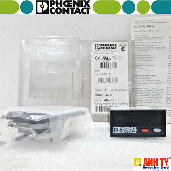 Màn hình digital hiển thị tín hiệu Phoenix Contact MCR-SL-D-U-I - 2864011Giá tốt nhất xem...0909186879 Email
 Bộ định áp Phoenix Contact MINI MCR-SL-CVS-24-5-10-NC - 2902822Giá tốt nhất xem...0909186879 Email
 Bộ khuếch đại chuyển mạch cách ly Phoenix Contact MACX MCR-EX-SL-NAM-2RO -Giá tốt nhất xem...0909186879 Email
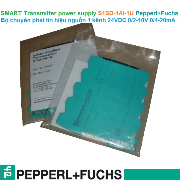 Bộ chuyển phát tín hiệu nguồn Pepperl+Fuchs S1SD-1AI-1U | 24VDC 0/2-10V 0/4-20mAGiá tốt nhất xem...0909186879 Email
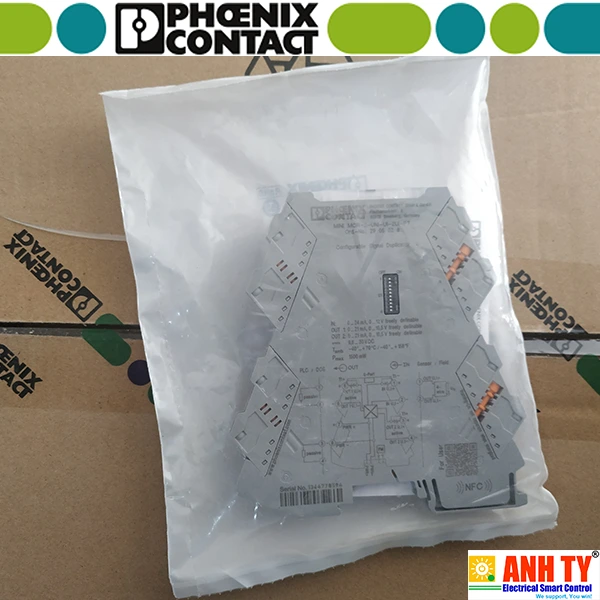 Bộ chuyển đổi tín hiệu điện trở nhiệt Phoenix Contact MINI MCR-2-RTD-UI-C -Giá tốt nhất xem...0909186879 Email
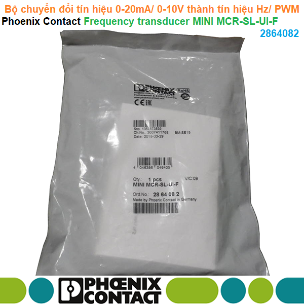 Bộ chuyển đổi tín hiệu 0-20mA/ 0-10V thành tín hiệu Hz hoặc PWM - Phoenix Contact - Frequency transducer MINI MCR-SL-UI-F 2864082Giá tốt nhất Xem...0909186879 Email
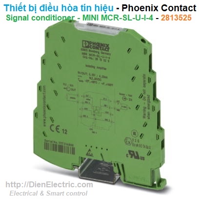 Bộ chuyển đổi tín hiệu V-A Phoenix Contact MINI MCR-SL-U-I-4 - 2813525Giá tốt nhất Xem...0909186879 Email
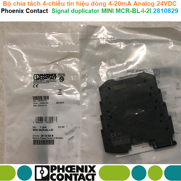 Bộ chia tách 4-chiều tín hiệu dòng 4-20mA Analog 24VDC - Phoenix Contact - Signal duplicator MINI MCR-BL-I-2I - 2810829Giá tốt nhất Xem...0909186879 Email
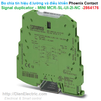 Bộ chia tín hiệu đo lường và điều khiển - Phoenix Contact - Signal duplicator - MINI MCR-SL-UI-2I-NC - 2864176Giá tốt nhất Xem...0909186879 Email
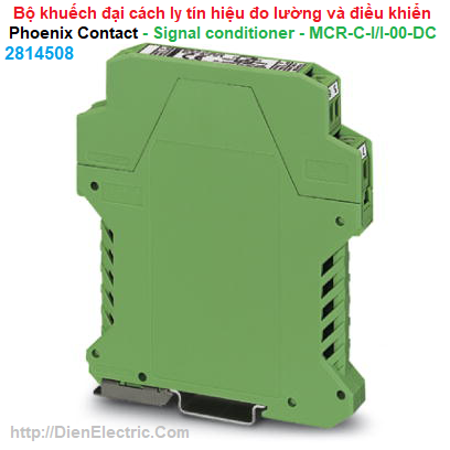 Bộ khuếch đại cách ly tín hiệu đo lường và điều khiển - Phoenix Contact - Signal conditioner - MCR-C-I/I-00-DC - 2814508Giá tốt nhất Xem...0909186879 Email
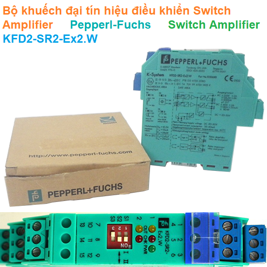 Bộ khuếch đại tín hiệu Switch Amplifier - Pepperl-Fuchs - Switch Amplifier KFD2-SR2-Ex2.WGiá tốt nhất Xem...0909186879 Email
 Bộ chia khuếch đại tín hiệu Phoenix Contact MINI MCR-2-UNI-UI-2UI-C - 2905025Giá tốt nhất Xem...0909186879 Email
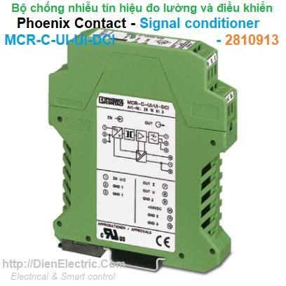 Bộ chống nhiễu tín hiệu đo lường và điều khiển - Phoenix Contact - Signal conditioner - MCR-C-UI-UI-DCI - 2810913Giá tốt nhất Xem...0909186879 Email
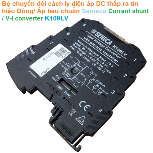 Bộ chuyển đổi cách ly điện mV ra tín hiệu Dòng/ Áp DC chuẩn - Seneca - Current shunt / V-I converter K109LVGiá tốt nhất Xem...0909186879 Email