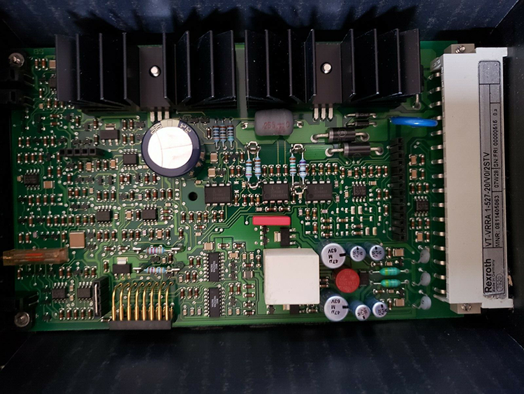
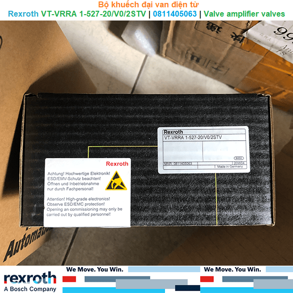
Bộ khuếch đại van điện từ Rexroth VT-VRRA 1-527-20/V0/2STV | 0811405063 | Valve amplifier for high-response valves
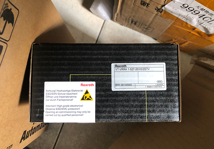
Bộ khuếch đại VT-VRRA1 điều khiển van điện từ servo tiêu chuẩn với phản hồi DC-LVDT cho hoạt động trực tiếp 4WRPH..L-2X và 2 giai đoạn 4WRL ..- 3X. Đây là những bộ khuếch đại cơ bản. Vì các thành phần này thường được sử dụng trong các ứng dụng vòng kín, các tính năng khác như độ dốc, thời gian và bù ống (bước nhảy) là không cần thiết./
The amplifier VT-VRRA1 controls standard servo solenoid valves with DC-LVDT feedback for direct operated 4WRPH..L-2X and 2-stage 4WRL..-3X. These are basic amplifiers. Since these components are normally used in closed loop applications, other features like ramp, time, and spool compenstion (jump) are not needed.
Features
- Bộ khuếch đại tương tự ở định dạng Eurocard/
Analog amplifiers in Eurocard format
- Giai đoạn đầu ra được kiểm soát/
Controlled output stage
- Kích hoạt đầu vào/
Enable input
- Đầu ra chống ngắn mạch/
Short-circuit-proof outputs
- Tùy chọn điều chỉnh: Điểm không van/
Adjustment options: Valve zero point
- Phát hiện đứt cáp cho cáp có giá trị thực tế/
Cable break detection for actual value cable
- Điều khiển vị trí vòng kín với các đặc tính PID/
Closed-loop position control with PID characteristics
- Controlled output stage
- Enable input
- Short-circuit proof outputs
- Adjustment possibilities – zero point of valve
- Cable break detection for actual value cable
- Position control with PID behavior
- Component series 2X
- Analog, euro-card format
- Suitable for controlling pilot operated directional control valves, progressive with linear fi ne control
4WRL 10...35 V/V1...M-3X..,
4WRL 10...35 E/W...S-3X...,
4WRL 10...25 V/V1...M-3X...-750,
3WRCB 25...50...M-1X...
Preferred types
| Amplifier type |
Material number |
For directional control valves, pilot operated, with electrical position feedback |
| VT-VRRA1-527-20/V0/2STV |
0811405063 |
4WRL 10…35 V/V1…M-3X… |
| 4WRL 10…35 E/W…S-3X… |
| 4WRL 10…25 V/V1…M-3X…-750 |
| 3RCB 25…50…M-1X… |
Suitable card holder:
- Open card holder T 3002-1-2X/32F
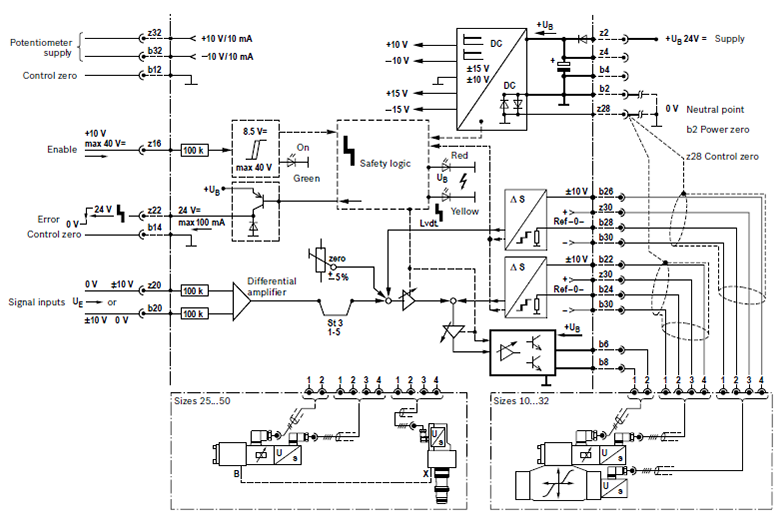
Block diagram with pin assignment, option 2STV
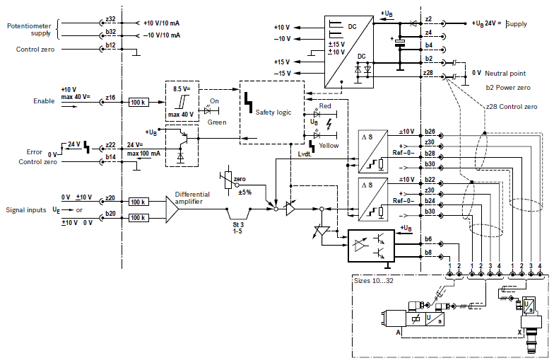
Block diagram with pin assignment, option PO-IS
Technical data (For applications outside these parameters, please consult us)
 Supply voltage
UB at z2 – b2
Nominal 24 V = battery voltage 21...40 V, rectified alternating voltage Ueff = 21...28 V (one-phase, full-wave rectifier)
Smoothing capacitor, separately
at z2 – b2
Recommendation: capacitor module VT 11110 (see data sheet 30750)
(only necessary if the ripple of UB > 10 %)
Valve solenoid, max.
A/VA
2.7/40 (pilot control valve, size 6)
Current consumption, max.
A
1.7
Current consumption may increase with min. UB and extreme cable lengths to the control solenoid
Power consumption (typical)
W
37
Input signal (command value)
b20: 0...±10 V
z20: 0...±10 V }Differential amplifier
(Ri = 100 kΩ) }Differential amplifier
Signal source
Potentiometer 10 kΩ
Supply with ±10 V from b32, z32 (10 mA) or external signal source
Enable output stage
At z16, U = 8.5...40 V, Ri = 100 kΩ, LED (green) on front panel
Position transducer Supply
b30: –15 V
z30: +15 V
Pilot control valve
Actual value signal b22: 0...±10 V
Actual value reference b24
Main stage
Actual value signal b26: 0...±10 V
Actual value reference b28
Solenoid output
b6 – b8 Imax
Clocked current controller
2.7 A
Cable lengths between amplifier and valve
Solenoid cable: Up to 20 m 1.5 mm2
20 to 60 m 2.5 mm2
Position transducer: 4 x 0.5 mm2 (shielded)
Special features
Cable break protection for actual value cable, Position control with PID behavior, Pulsed output stage, Fast energization and fast deletion for short actuating times, Short-circuit-proof outputs
Adjustment
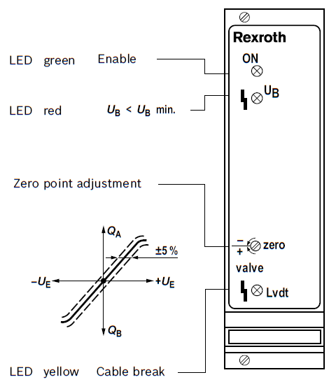
Zero point via trimming potentiometer ±5 %
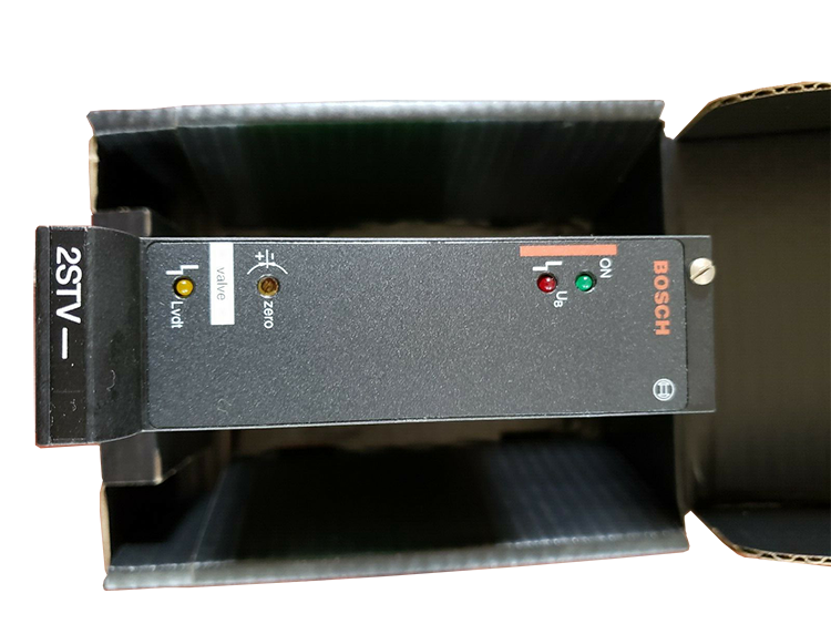
LED indicators
Green: Enable
Yellow: Cable break actual value
Red: Undervoltage(UB too low)
Error message
– Cable break actual value
– UB too low
– ±15 V stabilization
z22: Open collector output to +UB
Max. 100 mA; no error: +UB
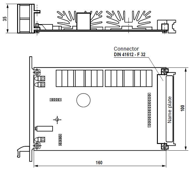
Circuit board format
mm
(100 x 160 x approx. 35) / (W x L x H)
Europe format with front panel 7 TE
Plug-in connection
Connector DIN 41612 – F32
Ambient temperature
°C
0...+70
Storage temperature range
°C
–20...+70
Weight
m
0.36 kg
Notice:
Power zero b2 and control zero b12 or b14 or z28 must be separately led to the central ground (neutral point).
Display/ adjustment elements
Dimensions (dimensions in mm)
Project planning information / maintenance instructions / additional information
- The amplifi er card may only be unplugged and plugged when de-energized.
- The distance to aerial lines, radios and radar systems must be suffi cient (> 1 m).
- Do not lay solenoid and signal lines near power cables.
- For signal lines and solenoid conductors, we recommend using shielded cables.
The cable shield must be connected to the control cabinet extensively and must be as short as possible.
- The valve solenoid must not be connected to free-wheeling diodes or other protection circuits.
- The cable lengths and cross-sections specifi ed on page 5 must be complied with.
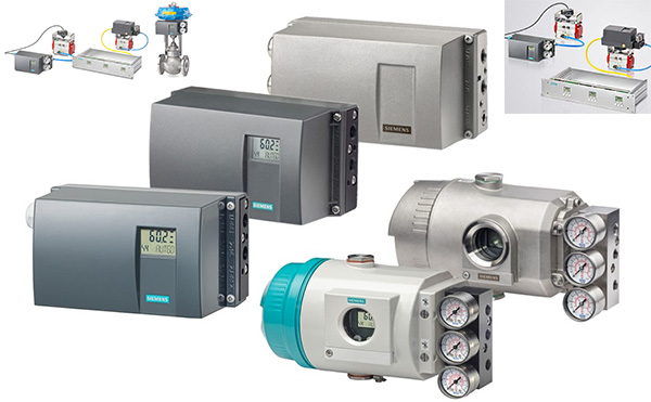


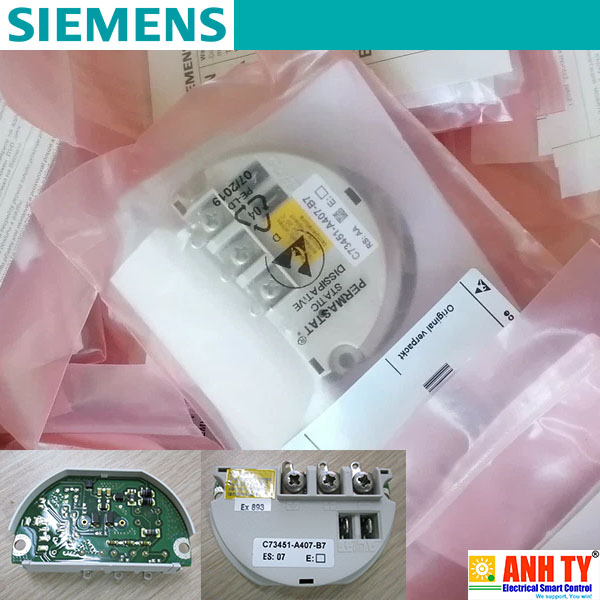 Mô-đun kết nối Siemens C73451-A407-B7Giá tốt nhất xem...0909186879 Email
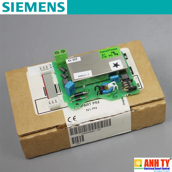 Mô-đun kết nối tín hiệu đầu ra analog Siemens 6DR4004-8JGiá tốt nhất xem...0909186879 Email
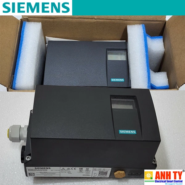 Bộ định vị khí nén 4-20mA 1/2NPT 1/4NPT Siemens 6DR5013-0FN00-0AA9 R1BGiá tốt nhất xem...0909186879 Email
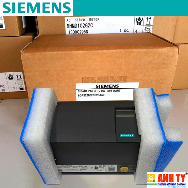 Bộ định vị van Siemens 6DR5220-0EG02-0AA0 | 4-20mA 3/4-wire HART Ex/nExGiá tốt nhất xem...0909186879 Email
 Bộ điều khiển van Siemens 6DR5010-0NM00-0AA0Giá tốt nhất xem...0909186879 Email
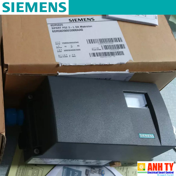 Siemens 6DR5110-0NN01-0AA0 | SIPART PS2 Smart electropneumatic positioner -Bộ định vị khí nén điện thông minh cho bộ truyền động tuyến tính và bán phần bằng khí nén 2-wire 4-20mA HARTGiá tốt nhất Xem...0909186879 Email
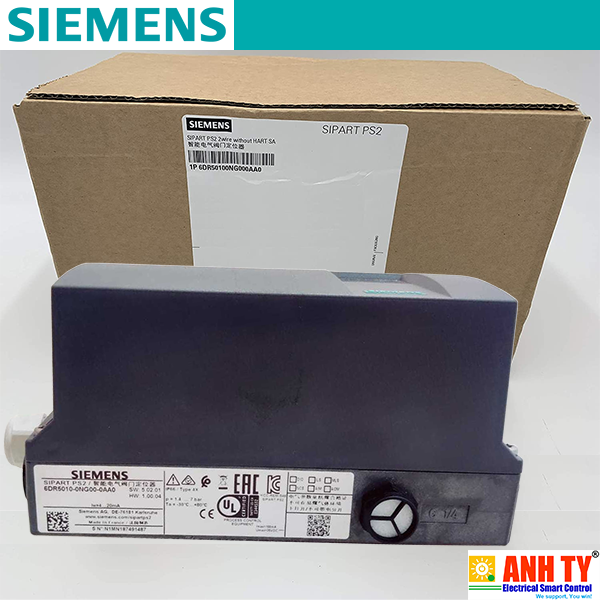 Siemens 6DR5010-0NG00-0AA0 | SIPART PS2 Smart electropneumatic positioner -Bộ định vị điện khí nén 2-wire 4-20mA M20x1.5 G 1/4Giá tốt nhất Xem...0909186879 Email
 Rexroth VT-VRRA 1-527-20/V0/2STV | 0811405063 | Valve amplifier for high-response valves -Bộ khuếch đại van điện từGiá tốt nhất Xem...0909186879 Email
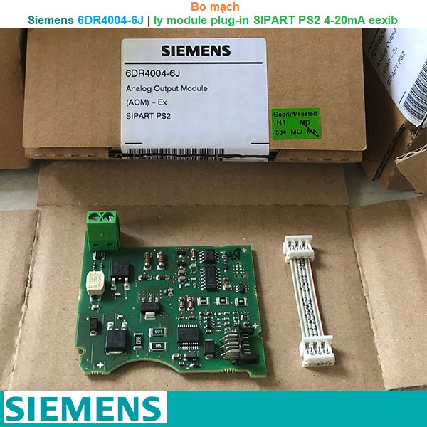 Siemens 6DR4004-6J | Iy module plug-in SIPART PS2 4-20mA eexibGiá tốt nhất Xem...0909186879 Email
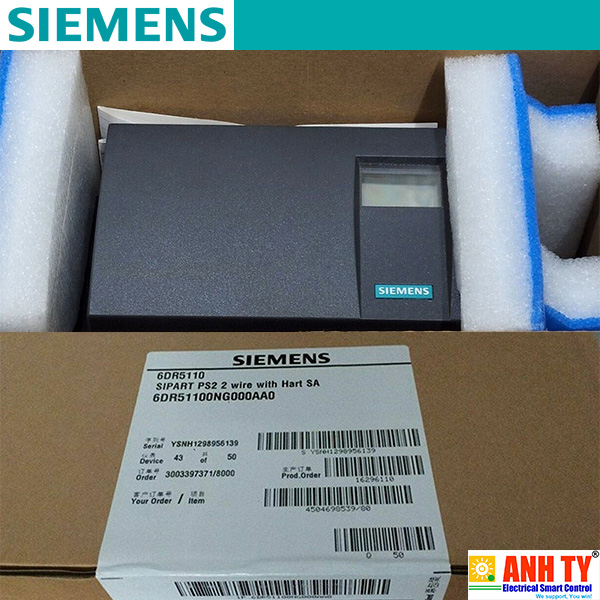 Bộ định vị điện khí nén Siemens 6DR5110-0NG00-0AA0Giá tốt nhất Xem...0909186879 Email
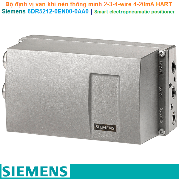 Siemens 6DR5212-0EN00-0AA0 | Smart electropneumatic positioner -Bộ định vị van khí nén thông minh 2-3-4-wire 4-20mA HARTGiá tốt nhất Xem...0909186879 Email
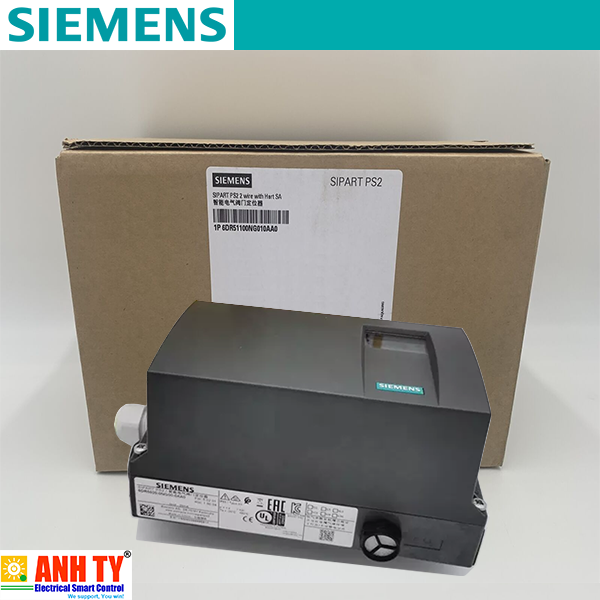 Bộ định vị điện-khí nén Siemens 6DR5120-0NG00-0AA0Giá tốt nhất Xem...0909186879 Email
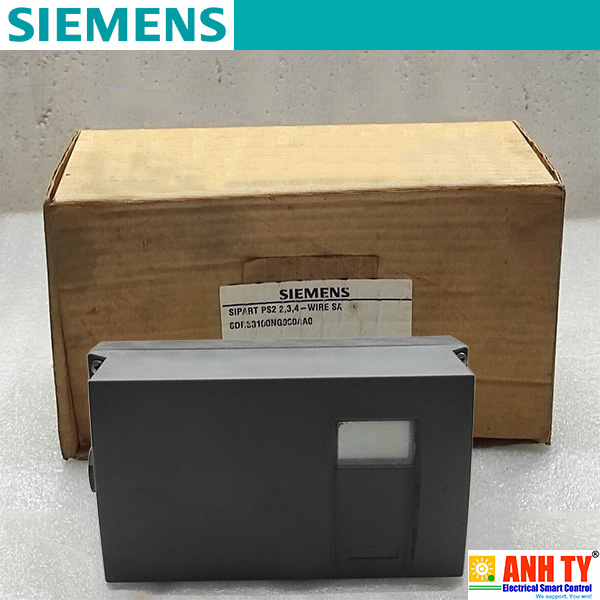 Bộ điều khiển van khí nén Siemens 6DR5310-0NG00-0AA0Giá tốt nhất Xem...0909186879 Email
 Mô-đun kết nối tín hiệu đầu ra analog Siemens 6DR4004-8JGiá tốt nhất Xem...0909186879 Email