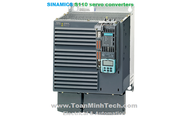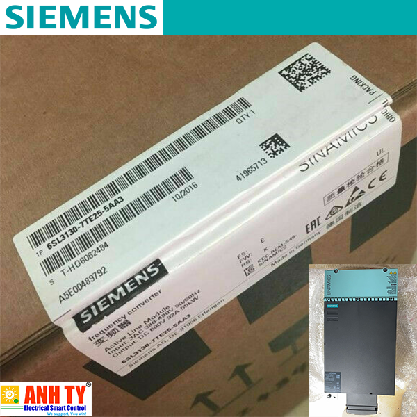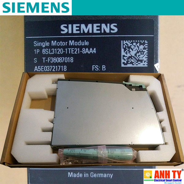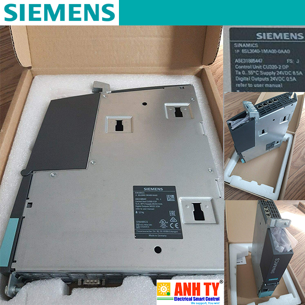


SINAMICS S110 can be used in numerous applications. Typical examples are:
- Handling equipment
The SINAMICS S110 servo drive is designed for connection to both synchronous servomotors and asynchronous (induction) motors. It supports all the most popular types of encoder.
A variety of fieldbus interfaces is provided for linking the unit to a higher-level control system. Alternatively, it can be controlled via ±10 V and a pulse direction interface.
The so-called basic positioner (EPos) is an integral component of SINAMICS S110. It provides a simple method of solving positioning tasks.
SINAMICS S110 is a flexible, versatile system.
Synchronous servomotors and asynchronous (induction) motors with outputs up to 90 kW (125 hp) can be used to implement rotary or linear axes. DRIVE-CLiQ motors can be connected simply by means of the integrated DRIVE-CLiQ interface. This means that the electronic rating plate of the motor is easy to read out, reducing the engineering time and cost involved in commissioning the drive.
Furthermore, the SINAMICS S110 features an integrated encoder interface for optional use. It is capable of evaluating HTL/TTL and SSI encoders.
In addition to pure point-to-point positioning, SINAMICS S110 naturally also offers on-the-fly changeover from continuous operation to positioning mode in order, for example, to precisely position objects transported randomly on a conveyor belt. Even simple traversing profiles with different motion cycles and wait times can be executed automatically by SINAMICS S110.
The CU305 Control Unit of the SINAMICS S110 is equipped with an integrated communication interface for linking the inverter to an automation system. A PROFINET or PROFIBUS interface can be ordered. Standardized protocols for linking to a higher-level control are supported – the PROFIdrive profile for positioning mode and the PROFIsafe profile for safety-related communication.
The inverter is thus perfectly coordinated with the SIMATIC S7 automation system. The devices are linked by means of PROFIBUS and the SIMATIC S7 uses standard function blocks to communicate with the drive. In addition, the STARTER commissioning tool can be seamlessly integrated into STEP 7, the SIMATIC's programming software.
Every drive contains a number of input and output variables which can be freely and independently interconnected using Binector Connector Technology (BICO). A binector is a logic signal which can assume the value 0 or 1. A connector is a numerical value, e.g. the actual speed or current setpoint.
The drive can be adapted easily and precisely to a wide range of customized requirements using the "free function blocks" integrated in the CU305 Control Unit. The available range of blocks includes simple logic blocks such as AND/OR elements, as well as more complex devices such as smoothing elements or limit-value monitors. All blocks can be flexibly interconnected using BICO (Binector-Connector) technology, ensuring that signals are processed quickly and close to the drive which helps reduce the load on the higher-level control.
The time characteristics of input and output variables associated with drives can be measured by the integrated trace function and displayed using the STARTER commissioning tool. The trace can record up to 4 signals simultaneously. Recording can be triggered as a function of freely selectable boundary conditions, e.g. the value of an input or output variable.
The integrated safety functions of SINAMICS S110 provide highly effective application-oriented protection for personnel and machinery (terms as defined in IEC 61800-5-2).
The following Safety Integrated Basic Functions are included as standard:
- Safe Torque Off (STO)
The following Safety Integrated Extended Functions are optionally available:
The Safety Integrated functions are fully integrated into the drive system. They can be activated via fail-safe digital inputs on the CU305 Control Unit or via PROFINET or PROFIBUS with PROFIsafe.
The Safety Integrated functions are implemented electronically and therefore offer short response times in comparison to solutions with externally implemented monitoring functions.
Additional information is provided in chapter Highlights, section Safety Integrated.
Memory cards
The memory card can be used as an option for SINAMICS S110. The relevant slot is located underneath the CU305 Control Unit. The complete functionality of SINAMICS S110 can be saved on the memory card: the parameter settings and the firmware. When service is required, e.g. after the inverter has been replaced and the data has been downloaded from the memory card, the drive system is immediately ready for use once more.
A SINAMICS Micro Memory Card (MMC) is essential, if the optional Safety Integrated Extended Functions are used. The necessary license is saved on the MMC.
Intelligent Operator Panel (IOP)
The IOP supports both entry-level personnel and drive experts. Thanks to the large plain text display, menu-based operation and application wizards, it is easy to commission, diagnose and locally control standard drives.
The IOP can be connected to the RS232 interface of the CU305 Control Unit using the appropriate connecting cable. Mounting the IOP directly on the CU305 Control Unit is not possible.
The following units are equipped as standard with varnished or partially varnished modules:
- Blocksize format units
The varnish coating protects the sensitive SMD components against corrosive gases, chemically active dust and moisture.
|
SINAMICS S110 – Summary of the most important functions |
|
|---|---|
|
Control method |
Servo control |
| Asynchronous (induction) motor |
Torque control with encoder |
| Synchronous motor |
Torque control with encoder |
|
Control function |
V/f characteristic |
| Asynchronous (induction) motor |
Basic linear |
| Synchronous motor |
– |
|
Basic positioner (EPos) |
Absolute and relative positioning |
|
Safety Integrated |
Safe Torque OFF (STO) |
|
Protection functions |
Undervoltage DC link voltage |
|
Functions for simplified commissioning |
Electronic rating plate for motors with DRIVE-CLiQ |
|
Free function blocks |
Logic and arithmetic blocks |
|
Data sets |
2 command data sets |
|
Further software functions |
BICO interconnection |
SINAMICS S110 provides powerful and precise positioning functions. Due to its flexibility and adaptability, the basic positioner can be used for a wide range of positioning tasks.
The functions are easy to handle both during commissioning and during operation. Furthermore, they are characterized by their comprehensive monitoring functions.
Many applications can be carried out without external position controllers.
The EPos basic positioner is available as a function module that can be activated in the drive,, and is used for the absolute/relative positioning of linear and rotary axes (modulo) with both rotary and linear motor encoders (indirect measuring system).
User-friendly configuring and commissioning including control panel (operation using PC) and diagnostics with the STARTER commissioning tool.
In addition to extremely flexible positioning functions, EPos offers a high degree of user-friendliness and reliability thanks to integral monitoring and compensation functions.
Different operating modes and their functionality increase flexibility and plant productivity, for example, by means of "on-the-fly" and bumpless correction of the motion control.
Preconfigured PROFIdrive positioning frames are available which, when selected, automatically establish the internal "connection" to the basic positioner.
Lower-level closed-loop position control with the following essential components
- Position actual value sensing (including the lower-level measuring probe evaluation and reference mark search)
Mechanical system
Limits
Referencing and alignment
Traversing blocks mode (16 traversing blocks)
- Positioning using traversing blocks stored in the drive unit, including block change enable conditions and specific tasks for a previously referenced axis
Direct setpoint input (MDI) mode
Jog mode
- Closed-loop position controlled traversing of the axis with "endless position controlled" or "jog incremental" modes (traverse through a "step width"), which can be toggledThe following electronic configuring aids and engineering tools are available for the SINAMICS S110 servo drives:
The interactive catalog CA 01 – the offline Industry Mall of Siemens on DVD‑ROM – contains over 100 000 products with approximately 5 million possible drive system product variants. The Drive Technology Configurator (DT Configurator) has been developed to facilitate selection of the correct motor and/or inverter from the wide spectrum of drives. It is integrated in Catalog CA 01 as an add-on on DVD‑ROM.
In addition, the DT Configurator can be used on the Internet without requiring any installation. The DT Configurator can be found in the Siemens Industry Mall at the following address:
http://www.siemens.com/dt-configurator
The SIZER for Siemens Drives engineering tool makes it easy to engineer the SINAMICS drive family. It provides support when selecting the hardware and firmware components necessary to implement a drive task. SIZER for Siemens Drives is designed to support configuring of the entire drive system.
You can find further information on the SIZER for Siemens Drives engineering tool in the chapter Engineering tools.
The SIZER for Siemens Drives engineering tool is available free on the Internet at
http://www.siemens.com/sizer
The STARTER commissioning tool allows menu-prompted commissioning, optimization and diagnostics. Apart from the SINAMICS drives, STARTER is also suitable for MICROMASTER 4 devices.
You can find further information about the STARTER commissioning tool in the chapter Engineering tools.
Additional information about the STARTER commissioning tool is available on the Internet at
http://www.siemens.com/starter
Drive ES is the engineering system that can be used to integrate the communication, configuration and data management functions of Siemens drive technology into the SIMATIC automation world easily, efficiently and cost-effectively. Two software packages are available for SINAMICS – Drive ES Basic and Drive ES PCS.
You can find further information about the Drive ES engineering system in the chapter Engineering tools.
Additional information about the Drive ES engineering system is available on the Internet at
http://www.siemens.com/drive-es
Unless specified otherwise, the following technical specifications are valid for all the following components of the SINAMICS S110 drive system.
|
Electronics power supply |
24 V DC -15%/+20% |
|---|---|
|
Vibratory load |
|
| Transport 1) acc. to EN 60721-3-2 |
|
| Control Units and Power Modules |
Class 2M3 |
| Operation Test values acc. to EN 60068‑2‑6 |
|
|
|
10 ... 58 Hz: Constant deflection 0.075 mm 58 ... 150 Hz: Constant acceleration = 9.81 m/s2 (1 × g) |
|
Shock load |
|
| Transport 1) acc. to EN 60721-3-2 |
|
| Control Units and Power Modules |
Class 2M3 |
| Operation Test values acc. to EN 60068‑2‑27 |
|
| Power Modules frame sizes FSA and FSB |
147 m/s2 (15 × g)/11 ms |
| Power Modules frame sizes FSC to FSF |
- 49 m/s2 (5 × g)/30 ms |
|
Ambient conditions |
|
| Protection class according to EN 61800‑5‑1 |
Class I (with protective conductor system) and Class III (PELV) |
| Touch protection |
DIN VDE 0106 Part 100 and BGV A 3 when used properly |
| Type of cooling |
Internal ventilator, power units with increased air cooling by built-in fans |
|
Permissible ambient/coolant temperature (air) during operation |
|
| Power Modules |
0 ... 40 °C (32 ... 104 °F) without derating, |
| Control Units, supplementary system components, DC link components and Sensor Modules |
0 … 55 °C (32 … 131 °F) |
|
Climatic ambient conditions |
|
| Storage 1) acc. to EN 60721‑3‑1 |
Class 1K4 |
| Transport 1) acc. to EN 60721-3-2 |
Class 2K4 |
| Operation acc. to EN 60721‑3‑3 |
Class 3K3 |
|
Environmental class/harmful chemical substances |
|
| Storage 1) acc. to EN 60721‑3‑1 |
Class 1C2 |
| Transport 1) acc. to EN 60721-3-2 |
Class 2C2 |
| Operation acc. to EN 60721‑3‑3 |
Class 3C2 |
|
Organic/biological influences |
|
| Storage 1) acc. to EN 60721‑3‑1 |
Class 1B1 |
| Transport 1) acc. to EN 60721-3-2 |
Class 2B1 |
| Operation acc. to EN 60721‑3‑3 |
Class 3B1 |
|
Degree of pollution According to EN 61800‑5‑1 |
2 |
1) In transport packaging.
|
European standards |
|
|---|---|
|
EN 61508‑1 |
Functional safety of electrical/electronic/programmable electronic safety-related systems |
|
EN 50370‑1 |
Electromagnetic compatibility (EMC) – Product family standard for machine tools |
|
EN 55011 |
Industrial, scientific and medical high-frequency devices (ISM devices) – radio interference – limit values and measuring techniques |
|
EN 60204‑1 |
Electrical equipment of machines |
|
EN 61800-3 |
Variable-speed electric drives |
|
EN 61800-5-1 |
Adjustable-speed electrical power drive systems |
|
North American standards |
|
|
UL508C |
Power Conversion Equipment |
|
CSA C22.2 No. 14 |
Industrial Control Equipment |
|
Approvals |
|
|
cULus |
Testing by UL (Underwriters Laboratories, http://www.ul.com) according to UL and CSA standards |
For satisfactory and reliable operation of the drive, original components of the SINAMICS system and the original Siemens accessories as described in Catalog D 31 and the Configuration Manuals, in the functional descriptions or user manuals should be used.
The user must observe the configuring instructions.
Combinations that differ from the configuring instructions (also in conjunction with non-Siemens products) require a special agreement.
If non-original components are used, for example, even in the case of a repair, approvals such as UL, EN and Safety Integrated may become invalid. This may also result in the operating authorization for the machine in which the non-Siemens components are installed becoming invalid.
All of the approvals, certificates, declarations of conformity, test certificates, e.g. CE, UL, Safety Integrated, have been performed with the associated system components as they are described in the Catalogs and Configuration Manuals. The certificates are only valid if the products are used with the described system components, are installed according to the Installation Guidelines and are used for their intended purpose. In other cases, the vendor of these products is responsible for arranging that new certificates are issued.
Note:
The products described in Catalog D 31 may cause high-frequency disturbances in a residential environment and necessitate the implementation of interference-suppression measures.
(Nguyễn Thảo Trường - http://DienElectric.com theo Siemens)
