dienelectrics@gmail.com
 0909186879 dienelectrics@gmail.com

With its separate power unit and Control Unit, the SINAMICS S120 drive system can be perfectly adapted to a wide variety of different drive tasks.
The Control Unit is selected according to the number of drives to be controlled and the required performance level, while the power unit must be rated to meet the energy requirements of the system. The connection between the Control Unit and power unit is made very simply using the DRIVE-CLiQ digital system interface.
The following drive units are available in the chassis format:
- Power ModulesThe simplest version of a SINAMICS S120 drive system comprises a CU310‑2 Control Unit and a Power Module.
In Power Modules specifically designed for single drives without regenerative feedback into the line supply, the line-side infeed and the motor-side power unit are combined in one unit.
Generated energy produced during braking is converted to heat in braking resistors.
The Control Unit is plugged onto the Power Module; in addition to the complete control intelligence, the Control Unit also has all the drive interfaces for communication with higher-level systems and interfacing of add-on components.
Line Modules contain the central line infeed for the DC link. Various Line Modules can be selected to address the various application profiles:
- Basic Line Modules
Basic Line Modules
Basic Line Modules are designed only for infeed operation, i.e. they are not capable of recovering energy to the line supply. If regenerative energy is produced, e.g. when drives brake, it must be converted into heat using a Braking Module and a braking resistor.
A line filter can be optionally installed in order to ensure compliance with the limits stipulated for Category C2 in EN 61800‑3.
Smart Line Modules
Smart Line Modules can supply energy and return regenerative energy to the supply system. A Braking Module and braking resistor are required only if the drives need to be decelerated in a controlled manner after a power failure (i.e. when energy cannot be recovered to the supply). For an infeed using a Smart Line Module, the appropriate line reactor is required.
A line filter can be optionally installed in order to ensure compliance with the limits stipulated for Category C2 in EN 61800‑3.
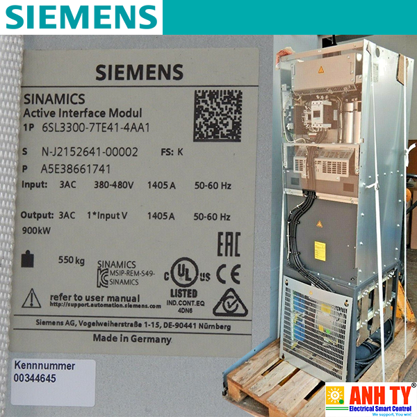
Active Line Modules
Active Line Modules can supply energy and return regenerative energy to the supply system. A Braking Module and braking resistor are required only if the drives need to be decelerated in a controlled manner after a power failure (i.e. when energy cannot be recovered to the supply).
In contrast to Basic Line Modules and Smart Line Modules, Active Line Modules generate a controlled DC voltage that is kept constant despite fluctuations in the line supply voltage if the line supply voltage fluctuates within the permitted tolerance range. Active Line Modules draw a virtually sinusoidal current from the supply which limits any harmful harmonics. All of the components necessary to operate an Active Line Module are integrated in the Active Interface Module.
A line filter can be optionally installed in order to ensure compliance with the limits stipulated for Category C2 in EN 61800‑3.
A voltage DC link and an inverter for supplying a motor are integrated in the Motor Module.
Motor Modules are designed for multi-axis drive systems and are controlled by either a CU320‑2 or a SIMOTION D Control Unit. Motor
Modules are interconnected through the DC link.
One or several Motor Modules are supplied with energy for the motors via the DC link. Both synchronous and induction motors can be operated.
Since the Motor Modules share the same DC link, they can exchange energy with one another, i.e. if one Motor Module operating in generator mode produces energy, the energy can be used by another Motor Module operating in motor mode. The DC link is supplied with line supply voltage by a Line Module.
The control intelligence for all the drive axes integrated in the multi-axis group is combined in the Control Units. They also feature drive-related inputs/outputs and interfaces for communicating with higher-level controllers. Control Units are available with different ranges of functions and with different performance levels.
The structure of the drive system is defined by selecting the Control Unit and Power Module or Line Module and Motor Modules. The additional components provided allow optimum adaptation of the drive system to the application.
These components are subdivided into:
- Line-side components, e.g. line reactors and line filtersSINAMICS S120 components, including motors and encoders, are equipped with the high-performance DRIVE‑CLiQ system interface.
Line and Motor Modules for example are connected to the Control Unit – and Terminal Modules and Sensor Modules to the drive system via DRIVE‑CLiQ – simply and efficiently. Motors that also have this interface can be directly connected to the drive system.
Converter boards (Sensor Modules) for converting standard encoder signals to DRIVE‑CLiQ are available for third-party motors or retrofit applications.
An important digital linkage element of the SINAMICS S120 drive system are the electronic rating plates integrated in every component. They allow all drive components to be automatically identified via the DRIVE‑CLiQ link.
The electronic rating plate contains all the relevant technical data about that particular component. In addition to the technical data, the electronic rating plate includes logistical data (manufacturer ID, article number and ID). Since this data can be called up electronically on site or remotely, all the components used in a machine can always be individually identified, which helps simplify servicing.
The following devices are equipped as standard with coated modules:
- Blocksize format unitsThe coating on the modules protects the sensitive SMD components against corrosive gases, chemically active dust and moisture.
All of the copper busbars used are nickel-plated in order to achieve the best possible immunity to environmental effects. Further, it is possible to eliminate having to clean the contacts at the customer connections, which is required for bare copper connections.
Note:
For some components, parts of the copper busbars cannot be nickel-plated for technical reasons.
As customer interface to a higher-level control, as standard there is a PROFIBUS or PROFINET communication interface on the Control Unit CU320-2; there are also expansions such as the Terminal Module TM31, the Terminal Board TB30 and modules to communicate via CANopen or EtherNet/IP.
These interfaces can be used to connect the system to the higher-level controller using analog and digital signals, or to connect additional units.
For additional information, please refer to the SINAMICS Low Voltage Engineering Manual.
SINAMICS S120 can use a dynamic, high-precision closed-loop vector control (drive object type VECTOR), or a highly dynamic closed-loop servo control (drive object type SERVO).
The software functions available as standard are described below:
|
Software and protective functions |
Description |
|---|---|
|
Setpoint input |
The setpoint can be specified both internally and externally; internally as a fixed setpoint, motorized potentiometer setpoint or jog setpoint, externally via the communications interface or an analog input. The internal fixed setpoint and the motorized potentiometer setpoint can be switched or adjusted via control commands from any interface. |
|
Motor identification |
The automatic motor identification function makes commissioning faster and easier and optimizes closed-loop control of the drive. |
|
Ramp-function generator |
A user-friendly ramp-function generator with separately adjustable ramp-up and ramp-down times, together with adjustable rounding times in the lower and upper speed ranges, allows the drive to be smoothly accelerated and braked. This results in a good speed control response and contributes to the reduction of stress on the mechanical system. The down ramp can be parameterized separately for a quick stop. |
|
Vdc max controller |
The Vdc max controller automatically prevents overvoltages in the DC link, if the set down ramp is too short, for example. This may also extend the set ramp-down time. Note: This function only makes sense for single-axis applications. |
|
Kinetic buffering (KIP) |
For brief line supply failures, the kinetic energy of the rotating drive is used to buffer the DC link and therefore prevents fault trips. The drive converter remains operational as long as the drive can provide regenerative energy as a result of its motion and the DC link voltage does not drop below the shutdown threshold. When the line supply recovers within this time, the drive is again bumplessly accelerated up to its setpoint speed. |
|
Automatic restart |
The automatic restart switches the drive on again when the power is restored after a power failure, and ramps up to the current speed setpoint. |
|
Flying restart |
The flying restart function allows the converter to be switched to a motor that is still turning. With the voltage sensing capability provided by the optional VSM10, the flying restart time for large induction motors can be significantly reduced because the motor does not need to be de-magnetized. |
|
Technology controller (PID) |
Using the technology controller (PID controller) function module, level or flow controls and complex tension controls can be implemented, for example. The existing D component can act both on the system deviation well as on the actual value (factory setting). The P, I, and D components are set separately. |
|
Free function blocks (FFB) |
Using the freely programmable function blocks, it is easy to implement logic and arithmetic functions for controlling the SINAMICS drive. The blocks can be programmed at the operator panel or the STARTER commissioning tool. |
|
Drive Control Chart (DCC) |
Drive Control Chart (DCC) is an additional tool for the easy configuration of technological functions for SINAMICS. The block library contains a large selection of control, arithmetic and logic blocks as well as extensive open-loop and closed-loop control functions. The user-friendly DCC editor enables easy graphics-based configuration, allows control loop structures to be clearly represented and provides a high degree of reusability of charts that have already been created. DCC is an add-on for the STARTER commissioning tool (see section Engineering tools). |
|
SINAMICS Technology Extensions (SINAMICS TEC) |
The SINAMICS TEC are configurable functions or Siemens technologies that can be added to extend firmware functions. These extensions are designed to allow implementation of highly complex, application-specific tasks for various sectors - such as storage and retrieval machines. |
|
I2t sensing for motor protection |
A motor model stored in the converter software calculates the motor temperature based on the current speed and load. More exact measurement of the temperature, which also takes into account the influence of the ambient temperature, is possible by means of direct temperature measurement using KTY84 sensors in the motor winding. |
|
Motor temperature evaluation |
Motor protection by evaluating a KTY84, Pt1000, PTC or Pt100 temperature sensor. When a KTY84 temperature sensor is connected, the limit values can be set for alarm or shutdown. When a PTC thermistor is connected, the system reaction to triggering of the thermistor (alarm or trip) can be defined. |
|
Motor blocking protection |
A blocked motor is detected and protected against thermal overloading by a fault trip. |
|
Brake control |
"Simple brake control" for control of holding brakes: "Extended brake control" function module for complex brake control, e.g. for motor holding brakes and operational brakes: |
|
Write protection |
Write protection to prevent unintentional changing of the setting parameters (without password function). |
|
Know-how protection |
Know-how protection for encrypting stored data, e.g. to protect configuration know-how, and to protect against changes and duplication (with password function). |
|
Web server |
The integrated web server provides information about the drive unit via its web pages. The web server is accessed using a web browser via unsecured (http) or secured transfer protocol (https). |
|
Power unit protection |
Description |
|---|---|
|
Ground fault monitoring at the output |
A ground fault at the output is detected by a total current monitor and results in shutdown in grounded systems. |
|
Electronic short-circuit protection at the output |
A short-circuit at the output (e.g. at the converter output terminals, in the motor cable or in the motor terminal box) is detected and the converter shuts down with a "fault". |
|
Thermal overload protection |
An alarm is issued first when the overtemperature threshold responds. If the temperature continues to rise, the unit either shuts down or independently adjusts the pulse frequency or output current so that thermal load is reduced. Once the cause of the fault has been eliminated (e.g. cooling has been improved), the original operating values are automatically resumed. |
The most important directives and standards are listed below. These are used as the basis for the SINAMICS S120 built-in units in chassis format and they must be carefully observed to achieve an EMC-compliant configuration that is safe both functionally and in operation.
|
European directives |
|
|---|---|
|
2014/35/EU |
Low-voltage directive: |
|
2014/30/EU |
EMC directive: |
|
2006/42/EC |
Machinery Directive: |
|
European standards |
|
|
EN ISO 3744 |
Acoustics – Determination of the sound power level and sound energy level for noise sources that result from sound pressure measurements – envelope surface procedure of the accuracy class 2 for a largely free sound field over a reflecting plane |
|
EN ISO 13849-1 |
Safety of machinery – safety-related parts of control systems; |
|
EN 60146-1-1 |
Semiconductor converters – General requirements and line-commutated converters |
|
EN 60204-1 |
Safety of machinery – Electrical equipment of machines; |
|
EN 60529 |
Degrees of protection provided by enclosures (IP code) |
|
EN 61508-1 |
Functional safety of electrical/electronic/programmable electronic safety-related systems |
|
EN 61800-2 |
Adjustable speed electrical power drive systems |
|
EN 61800-3 |
Adjustable speed electrical power drive systems |
|
EN 61800-5-1 |
Adjustable speed electrical power drive systems |
|
EN 61800-5-2 |
Adjustable speed electrical power drive systems |
|
North American standards |
|
|
UL 508A |
Industrial Control Panels |
|
UL 508C |
Power Conversion Equipment |
|
UL 61800-5-1 |
Adjustable Speed Electrical Power Drive Systems - Part 5‑1: Safety requirements – Electrical, thermal and energy |
|
CSA C22.2 No. 14 |
Industrial Control Equipment |
|
Certificates of suitability |
|
|
cULus, cURus |
Testing by UL (Underwriters Laboratories, http://www.ul.com) according to UL and CSA standards |

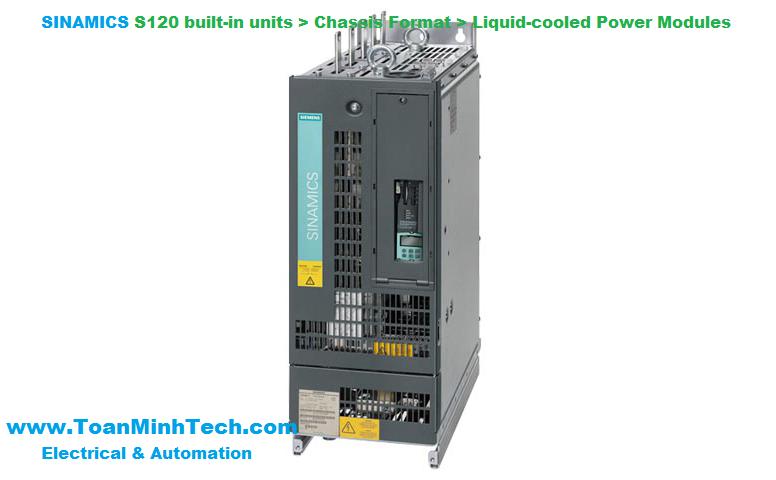
The SINAMICS S120 liquid-cooled drive units are specifically designed to address the requirements relating to liquid cooling; they are characterized by their high power density and optimized footprint. Liquid cooling dissipates heat much more efficiently than air cooling systems. As a result, liquid-cooled units are much more compact than air-cooled units with the same power rating. Since the heat losses generated by the electronic components are almost completely dissipated by the liquid coolant, only very small cooling fans are required. This means that the devices are quiet in operation. Due to their compact dimensions and almost negligible cooling air requirement, liquid-cooled units are the preferred solution wherever installation space is restricted and/or the ambient operating conditions are rough.
Control cabinets with liquid cooling are easy to implement as sealed units with degrees of protection of IP55.
The product portfolio includes the following liquid-cooled SINAMICS S120 built-in units:
- Power Modules
The associated system components such as line reactors, motor reactors, dv/dt filters plus VPL and sine-wave filters are air-cooled. Active Interface Modules are available in air-cooled and liquid-cooled versions.
Cabinet units in liquid-cooled version
Liquid-cooled SINAMICS S120 drive units are also available as cabinet units, including cooling system. See section SINAMICS S120 Cabinet Modules → Liquid-cooled units.

Example of a drive line-up with SINAMICS S120 liquid-cooled units
Unless clearly specified otherwise, the following technical data are valid for all the following components of the liquid-cooled SINAMICS S120 drive system in the chassis format.
|
Electrical specifications |
|||
|---|---|---|---|
|
Rated voltages |
380 ... 480 V 3 AC ±10 % (-15 % <1 min) 500 ... 690 V 3 AC ±10 % (-15 % <1 min) |
||
|
Line supply types |
Grounded TN/TT systems and non-grounded IT systems |
||
|
Line frequency |
47 ... 63 Hz |
||
|
Overvoltage category |
III to EN 61800‑5‑1 |
||
|
Electronics power supply |
24 V DC, -15 % +20 % |
||
|
Rated short-circuit current per IEC, in conjunction with the specified fuses or circuit breakers |
|
||
|
65 kA |
||
|
84 kA |
||
|
170 kA |
||
|
200 kA |
||
|
Rated short-circuit current SCCR according to UL508C (up to 600 V), in conjunction with the specified fuses or circuit breakers |
|
||
|
65 kA |
||
|
84 kA |
||
|
170 kA |
||
|
200 kA |
||
|
Control method |
Vector/Servo control with and without encoder or V/f control |
||
|
Fixed speeds |
15 fixed speeds plus 1 minimum speed, parameterizable (in the default setting, 3 fixed setpoints plus 1 minimum speed are selectable using terminal block/PROFIBUS/PROFINET) |
||
|
Skippable speed ranges |
4, parameterizable |
||
|
Setpoint resolution |
0.001 rpm digital (14 bits + sign) |
||
|
Braking operation |
With Active Line Modules, four-quadrant operation as standard (energy recovery). With Basic Line Modules, two-quadrant operation as standard, braking by means of an optional braking chopper, or alternatively by a Motor Module. |
||
|
Mechanical specifications |
|||
|
Degree of protection |
IP00 (IP20, without taking into account the connecting busbars) |
||
|
Protection class |
I acc. to EN 61800‑5‑1 |
||
|
Touch protection |
EN 50274/DGUV regulation 3 when used as intended |
||
|
Cooling method |
Liquid cooling with integrated heat exchanger in aluminum or stainless steel version |
||
|
Ambient conditions |
Storage 1) |
Transport 1) |
Operation |
|
Ambient temperature (air) |
-25 ... +55 °C (-13 ... +131 °F) Class 1K4 |
-25 ... +70 °C (-13 ... +158 °F) Class 2K4 |
Line-side components, Power Modules, Line Modules and Motor Modules: Control Units, supplementary system components, and Sensor Modules: DC link components and motor-side components: |
|
Relative humidity Condensation, splashwater, and ice formation not permitted (EN 60204, Part 1) |
5 ... 95 % Class 1K4 |
Max. 95 % at 40 °C (104 °F) Class 2K4 |
5 ... 95 % Class 3K3 |
|
Environmental class/harmful chemical substances |
Class 1C2 |
Class 2C2 |
Class 3C2 |
|
Organic/biological influences |
Class 1B1 |
Class 2B1 |
Class 3B1 |
|
Degree of pollution |
2 acc. to IEC/EN 61800‑5‑1 |
||
|
Installation altitude |
Up to 2000 m (6562 ft) above sea level without derating, |
||
|
Mechanical stability |
Storage 1) |
Transport 1) |
Operation |
|
Vibratory load |
|
Class 2M2 |
Test values
|
|
Shock load |
|
Class 2M2 |
Test values |
|
Compliance with standards |
|||
|
Conformances/certficates of suitability, according to |
CE (EMC Directive No. 2014/30/EU, Low Voltage Directive No. 2014/35/EU and Machinery Directive 2006/42/EC for functional safety) |
||
|
Radio interference suppression |
SINAMICS S120 chassis format units are not designed for connection to the public grid (first environment). Radio interference suppression is compliant with the EMC product standard for variable-speed drives EN 61800‑3, "Second environment" (industrial line supplies). EMC disturbances can occur when connected to the public grid. For further information, see section Configuration notes. |
||
1) In transport packaging.
Deviations from the specified class are underlined.
The following tables and sections describe the quality requirements of the coolant used in the liquid-cooled SINAMICS S120 drive system in chassis format.
|
Cooling circuit |
|
|---|---|
|
600 kPa |
|
70 kPa |
|
80 ... 200 kPa |
|
Dependent on ambient temperature, no condensation permitted 0 ... 45° C (32 ... 113 °F) without derating >45 … 50 °C (113 ... 122 °F), see derating data Anti-freeze essential for temperature range between 0 °C (32 °F) and 5 °C (41 °F) |
|
Coolant quality |
|
|
Distilled, demineralized, completely desalinated water or deionized water with reduced electrical conductivity ISO 3696, quality 3 or based on IEC 60993 |
|
<30 μS/cm (3 mS/m) |
|
5 ... 8 |
|
< 30 mg/l |
|
<10 mg/kg |
|
Filtered drinking water |
|
<2000 μS/cm |
|
6.5 ... 9 |
|
<200 mg/l |
|
<240 mg/l |
|
< 50 mg/l |
|
< 1.7 mmol/l |
|
< 340 mg/l |
|
< 100 μm |
|
|
The coolant definition specified here should only be considered as recommendation. For units that have been shipped, the information and data provided in the equipment manual supplied should be observed! |
|
Antifreeze |
Antifrogen N |
Antifrogen L |
DOWCAL 100 |
|---|---|---|---|
|
Manufacturer |
Clariant |
Clariant |
DOW |
|
Chemical base |
Ethylene glycol |
Propylene glycol |
Ethylene glycol |
|
Minimum concentration |
20 % |
25 % |
20 % |
|
Anti-freeze agent with minimum concentration |
-10 °C |
-10 °C |
-10 °C |
|
Maximum concentration |
45 % |
48 % |
44 % |
|
Anti-freeze agent with maximum concentration |
-30 °C |
-30 °C |
-30 °C |
|
Inhibitor content |
Contains inhibitors with nitrites |
Contains inhibitors that are free of nitrates, amines, borates and phosphates |
Contains inhibitors that are free of nitrates, amines and phosphates |
|
Biocide action with a concentration of |
> 20 % |
> 30 % |
> 20 % |
Biocides prevent corrosion that is caused by slime-forming, corrosive or iron-depositing bacteria. These can occur in closed cooling circuits with low water hardness and in open cooling circuits. Biocides must always be selected according to the relevant bacterial risks. Compatibility with inhibitors or antifreeze used with them must be checked on a case-by-case basis.
|
Inhibitors |
Antifrogen N |
ANTICORIT S 2000 A |
|---|---|---|
|
Manufacturer |
Clariant |
Fuchs |
|
Chemical base |
Ethylene glycol |
– |
|
Minimum concentration |
20 % |
4 % |
|
Maximum concentration |
45 % |
5 % |
Recommended service
The manufacturer of the antifreeze/inhibitor should analyze the coolant at least once per annum. The concentration and boundary conditions of the antifreeze/inhibitor should be checked. It may be necessary to correct the concentration on the plant side.
With liquid-cooled units, warm air can condense on the cold surfaces of heat sinks, pipes and hoses. This condensation depends on the air humidity and the temperature difference between the ambient air and the coolant.
The water which is produced as a result of condensation can cause corrosion as well as electrical damage such as creepage shorts and flashovers. As the SINAMICS units cannot prevent condensation if it is caused by the prevailing climatic conditions, any potential risk of condensation must be prevented by appropriate engineering or by precautionary measures implemented by the customer. These measures include the following:
- a fixed coolant temperature that has been adjusted to the expected air humidity or ambient temperature ensures that critical differences between the coolant and ambient air temperatures do not develop or
The temperature at which water vapor contained in the air condenses into water is known as the dew point. To prevent condensation reliably, the coolant temperature must always be higher than the dew point.
The table below specifies the dew point as a function of room temperature T and relative air humidity Φ for an atmospheric pressure of 100 kPa (1 bar). This corresponds to an installation altitude of 0 up to approximately 500 m (1640 ft) above sea level. Since the dew point drops as the air pressure decreases, the dew point values at higher installation altitudes are lower than the specified table values. It is therefore the safest approach to engineer the coolant temperature according to the values in the table for an installation altitude of zero.
|
Ambient temperature |
Relative air humidity Φ |
||||||||||
|---|---|---|---|---|---|---|---|---|---|---|---|
|
T |
20 % |
30 % |
40 % |
50 % |
60 % |
70 % |
80 % |
85 % |
90 % |
95 % |
100 % |
|
10 °C (50 °F) |
<0 °C (32 °F) |
<0 °C (32 °F) |
<0 °C (32 °F) |
0.2 °C (32.4 °F) |
2.7 °C (36.9 °F) |
4.8 °C (40.6 °F) |
6.7 °C (44.1 °F) |
7.6 °C (45.7 °F) |
8.4 °C (47.1 °F) |
9.2 °C (48.6 °F) |
10 °C (50 °F) |
|
20 °C (68 °F) |
<0 °C (32 °F) |
2 °C (35.6 °F) |
6 °C (42.8 °F) |
9.3 °C (48.7 °F) |
12 °C (53.6 °F) |
14.3 °C (57.7 °F) |
16.4 °C (61.5 °F) |
17.4 °C (63.3 °F) |
18.3 °C (64.9 °F) |
19.1 °C (66.4 °F) |
20 °C (68 °F) |
|
25 °C (77 °F) |
0.6 °C (33.1 °F) |
6.3 °C (43.3 °F) |
10.5 °C (50.9 °F) |
13.8 °C (56.8 °F) |
16.7 °C (62.1 °F) |
19.1 °C (66.4 °F) |
21.2 °C (70.2 °F) |
22.2 °C (72 °F) |
23.2 °C (73.8 °F) |
24.1 °C (75.4 °F) |
24.9 °C (76.8 °F) |
|
30 °C (86 °F) |
4.7 °C (40.5 °F) |
10.5 °C (50.9 °F) |
14.9 °C (58.8 °F) |
18.4 °C (65.1 °F) |
21.3 °C (70.3 °F) |
23.8 °C (74.8 °F) |
26.1 °C (79 °F) |
27.1 °C (80.8 °F) |
28.1 °C (82.6 °F) |
29 °C (84.2 °F) |
29.9 °C (85.8 °F) |
|
35 °C (95 °F) |
8.7 °C (47.7 °F) |
14.8 °C (58.6 °F) |
19.3 °C (66.7 °F) |
22.9 °C (73.2 °F) |
26 °C (78.8 °F) |
28.6 °C (83.5 °F) |
30.9 °C (87.6 °F) |
32 °C (89.6 °F) |
33 °C (91.4 °F) |
34 °C (93.2 °F) |
34.9 °C (94.8 °F) |
|
40 °C (104 °F) |
12.8 °C (55 °F) |
19.1 °C (66.4 °F) |
23.7 °C (74.7 °F) |
27.5 °C (81.5 °F) |
30.6 °C (87.1 °F) |
33.4 °C (92.1 °F) |
35.8 °C (96.4 °F) |
36.9 °C (98.4 °F) |
37.9 °C (100.2 °F) |
38.9 °C (102 °F) |
39.9 °C (103.8 °F) |
|
45 °C (113 °F) |
16.8 °C (62.2 °F) |
23.3 °C (73.9 °F) |
28.2 °C (82.8 °F) |
32 °C (89.6 °F) |
35.3 °C (95.5 °F) |
38.1 °C (101.6 °F) |
40.6 °C (105.1 °F) |
41.8 °C (107.2 °F) |
42.9 °C (109.2 °F) |
43.9 °C (111 °F) |
44.9 °C (112.8 °F) |
|
50 °C (122 °F) |
20.8 °C (69.4 °F) |
27.5 °C (81.5 °F) |
32.6 °C (90.7 °F) |
36.6 °C (97.9 °F) |
40 °C (104 °F) |
42.9 °C (109.2 °F) |
45.5 °C (113.9 °F) |
46.6 °C (115.9 °F) |
47.8 °C (118 °F) |
48.9 °C (120 °F) |
49.9 °C (121.8 °F) |
A detailed description of the cooling circuits and the recommended coolant is given in the SINAMICS Low Voltage Engineering Manual.
Liquid-cooled SINAMICS S120 chassis format units are rated for an ambient temperature of 45 °C (113 °F) and installation altitudes up to 2000 m (6562 ft) above sea level. At ambient temperatures > 45 °C (113 °F), the output current must be reduced. Ambient temperatures above 50 °C (122 °F) are not permissible. At installation altitudes > 2000 m (6562 ft) above sea level, it must be taken into account that the air pressure, and therefore air density, decreases as the height increases. As a consequence, the cooling efficiency and the insulation capacity of the air also decrease.

Current derating as a function of the temperature of the cooling liquid 1)

Current derating as a function of ambient temperature 1)
1) The factors of the two curves must not be multiplied. The highest value in each case must be assumed for the purposes of calculation, so that the derating factor in the worst-case scenario is 0.9.

Permissible ambient temperature as a function of installation altitude

Voltage derating as a function of installation altitude
Current derating for Power Modules and Motor Modules in chassis format as a function of the pulse frequency
To reduce motor noise or to increase output frequency, the pulse frequency can be increased relative to the factory setting (1.25 kHz or 2 kHz). When the pulse frequency is increased, the derating factor of the output current must be taken into account. This derating factor must be applied to the currents specified in the technical specifications.
For additional information, please refer to the SINAMICS Low Voltage Engineering Manual.
The following tables list the rated output currents of the SINAMICS S120 Power Modules and Motor Modules with pulse frequency set in the factory as well as the current derating factors (permissible output currents referred to the rated output current) for higher pulse frequencies.
Derating factor of the output current as a function of the pulse frequency for units with a rated pulse frequency of 2 kHz
|
Power Module |
Type rating |
Output current at 2 kHz |
Derating factor at pulse frequency |
||||
|---|---|---|---|---|---|---|---|
|
6SL3315-... |
kW (hp) |
A |
2.5 kHz |
4 kHz |
5 kHz |
7.5 kHz |
8 kHz |
|
380 ... 480 V 3 AC |
|||||||
|
1TE32-1AA3 |
110 (150) |
210 |
95 % |
82 % |
74 % |
54 % |
50 % |
|
1TE32-6AA3 |
132 (200) |
260 |
95 % |
83 % |
74 % |
54 % |
50 % |
|
1TE33-1AA3 |
160 (250) |
310 |
97 % |
88 % |
78 % |
54 % |
50 % |
|
1TE35-0AA3 |
250 (400) |
490 |
94 % |
78 % |
71 % |
53 % |
50 % |
|
1TE41-4AS3 1) |
800 (1000) |
1330 |
88 % |
55 % |
– |
– |
– |
1) This Motor Module has been specifically designed for loads demanding a high dynamic performance. The derating factor kIGBT and the derating characteristics can be ignored (see section “Duty cycles” in the SINAMICS Low Voltage Engineering Manual).
Derating factor of the output current as a function of the pulse frequency for units with a rated pulse frequency of 1.25 kHz
|
Motor Module |
Type rating at 400 V, 50 Hz (460 V, 60 Hz) or 690 V, 50 Hz (575 V, 60 Hz) |
Output current at 1.25 kHz |
Derating factor at pulse frequency |
||||
|---|---|---|---|---|---|---|---|
|
6SL3325-... |
kW (hp) |
A |
2 kHz |
2.5 kHz |
4 kHz |
5 kHz |
7.5 kHz |
|
380 ... 480 V 3 AC |
|||||||
|
1TE36-1AA3 |
315 (500) |
605 |
83 % |
72 % |
64 % |
60 % |
40 % |
|
1TE37-5AA3 |
400 (600) |
745 |
83 % |
72 % |
64 % |
60 % |
40 % |
|
1TE38-4AA3 |
450 (700) |
840 |
87 % |
79 % |
64 % |
60 % |
40 % |
|
1TE41-0AA3 |
560 (800) |
985 |
92 % |
87 % |
70 % |
60 % |
50 % |
|
1TE41-2AA3 |
710 (1000) |
1260 |
92 % |
87 % |
70 % |
60 % |
50 % |
|
1TE41-4AA3 |
800 (1150) |
1405 |
97 % |
95 % |
74 % |
60 % |
50 % |
|
500 ... 690 V 3 AC |
|||||||
|
1TG31-0AA3 |
90 (75) |
100 |
92 % |
88 % |
71 % |
60 % |
40 % |
|
1TG31-5AA3 |
132 (150) |
150 |
90 % |
84 % |
66 % |
55 % |
35 % |
|
1TG32-2AA3 |
200 (200) |
215 |
92 % |
87 % |
70 % |
60 % |
40 % |
|
1TG33-3AA3 |
315 (300) |
330 |
89 % |
82 % |
65 % |
55 % |
40 % |
|
1TG34-7AA3 |
450 (450) |
465 |
92 % |
87 % |
67 % |
55 % |
35 % |
|
1TG35-8AA3 |
560 (600) |
575 |
91 % |
85 % |
64 % |
50 % |
35 % |
|
1TG37-4AA3 |
710 (700) |
735 |
84 % |
74 % |
53 % |
40 % |
25 % |
|
1TG38-0AA3 2) |
800 (800) |
810 |
82 % |
71 % |
52 % |
40 % |
25 % |
|
1TG38-1AA3 |
800 (800) |
810 |
97 % |
95 % |
71 % |
55 % |
35 % |
|
1TG41-0AA3 |
1000 (1000) |
1025 |
91 % |
86 % |
64 % |
50 % |
30 % |
|
1TG41-3AA3 |
1200 (1250) |
1270 |
87 % |
79 % |
55 % |
40 % |
25 % |
|
1TG41-6AA3 |
1500 (1500) |
1560 |
87 % |
79 % |
55 % |
40 % |
25 % |
2) The Motor Module 6SL3325-1TG38-0AA3 is optimized for low overload; with an increased pulse frequency, the derating factor is higher than for the Motor Module 6SL3325-1TG38-1AA3.
The following tables list the maximum achievable output frequency as a function of the pulse frequency.
Maximum output frequencies achieved by increasing the pulse frequency in Vector mode
|
Pulse frequency |
Max. achievable output frequency |
|---|---|
|
1.25 kHz |
100 Hz |
|
2 kHz |
160 Hz |
|
2.5 kHz |
200 Hz |
|
4 kHz |
320 Hz |
|
5 kHz |
400 Hz |
Maximum output frequencies achieved by increasing the pulse frequency in Servo mode
|
Pulse frequency |
Max. achievable output frequency |
|---|---|
|
2 kHz |
300 Hz |
|
4 kHz |
300/550 Hz 3) |
3) Higher frequencies on request.For further information seehttps://support.industry.siemens.com/cs/document/104020669

Pressure drop for liquid-cooled built-in units in chassis format
The pressure drop characteristics are valid for water. If antifreeze is used, the characteristics typically shift to the left.
For further information, please refer to the SINAMICS Low Voltage Engineering Manual.
Liquid-cooled SINAMICS S120 units have an overload reserve, e.g. to handle breakaway torques. If larger surge loads occur, this must be taken into account in the configuration. For drives with overload requirements, the appropriate base load current must, therefore, be used as a basis for the required load.
The permissible overload levels are valid under the prerequisite that the drive units are operated with their base-load current before and after the overload condition based on a duty cycle duration of 300 s.
For temporary, periodic duty cycles with high variations of load within the duty cycle, the relevant sections of the SINAMICS Low Voltage Engineering Manual must be observed.
Power Modules and Motor Modules
The base-load current for a low overload IL is the basis for a duty cycle of 110 % for 60 s or 150 % for 10 s.

Low overload
The base-load current IH for a high overload is based on a duty cycle of 150 % for 60 s or 160 % for 10 s.

High overload
Line Modules
The base-load current for a high overload IH DC is the basis for a duty cycle of 150 % for 60 s or Imax DC for 5 s.

High overload

The Power Module comprises a line rectifier, a DC link and an inverter to supply the motor.
Power Modules are designed for drives that are not capable of regenerating energy to the mains supply. If the motor produces energy during braking, a Braking Module with braking resistors will be required.
Liquid-cooled Power Modules are especially suitable for applications where installation space is restricted and environmental conditions are harsh. Liquid cooling ensures efficient heat dissipation.
Power Modules in the chassis format can be connected to grounded TN/TT systems and non-grounded IT systems.
The liquid-cooled Power Modules have the following interfaces as standard:
- 1 line supply connection
The CU310-2 Control Unit can be integrated into the liquid-cooled Power Modules.
The status of the Power Modules is indicated via three LEDs.
The scope of supply of the Power Modules includes:
The Power Modules communicate with the higher-level control module via DRIVE‑CLiQ. The Control Unit in this case could be a CU310-2, CU320-2 or a SIMOTION D Control Unit. An external 24 V DC power supply is required to operate liquid-cooled Power Modules.

Connection example of a liquid-cooled Power Module in the chassis format
Note:
The integrated 24 V power supply at connector X42 can have a maximum load of 2 A. When the Control Unit is supplied from the integrated power supply, the total load of the digital outputs must be carefully observed to ensure that the 2 A is not exceeded.
|
Electrical specifications |
|
|---|---|
|
Line connection voltage Up to 2000 m (6562 ft) above sea level |
380 … 480 V 3 AC ±10 % (-15 % < 1 min) |
|
Line power factor for a 3 AC line supply voltage and rated output |
|
|
>0.96 |
|
0.75 ... 0.93 |
|
Efficiency |
> 98 % |
|
DC link voltage, approx. |
1.35 × line voltage |
|
Output voltage, approx. |
0 ... 0.97 × Uline |
|
Output frequency 1) |
|
|
0 ... 550 Hz |
|
0 ... 550 Hz |
|
0 ... 550 Hz |
|
Electronics power supply |
24 V DC -15 %/+20 % |
|
Main contactor control |
|
|
240 V AC, max. 8 A |
|
Safety Integrated |
Safety Integrity Level 2 (SIL2) acc. to IEC 61508, Performance Level d (PLd) acc. to EN ISO 13849‑1 and Control Category 3 acc. to EN ISO 13849‑1. |
1) Please note:
• The correlation between the maximum output frequency, pulse frequency and current derating. Higher output frequencies on request For further information see https://support.industry.siemens.com/cs/document/104020669
• The correlation between the minimum output frequency and permissible output current (current derating). Information is provided in the SINAMICS Low Voltage Engineering Manual.
|
Line voltage 380 V ... 480 V 3 AC |
Power Modules |
||||
|---|---|---|---|---|---|
|
|
|
6SL3315-1TE32-1AA3 |
6SL3315-1TE32-6AA3 |
6SL3315-1TE33-1AA3 |
6SL3315-1TE35-0AA3 |
|
Type rating |
|
|
|
|
|
|
kW |
110 |
132 |
160 |
250 |
|
kW |
90 |
110 |
132 |
200 |
|
hp |
150 |
200 |
250 |
400 |
|
hp |
150 |
200 |
200 |
350 |
|
Output current |
|
|
|
|
|
|
A |
210 |
260 |
310 |
490 |
|
A |
205 |
250 |
302 |
477 |
|
A |
178 |
233 |
277 |
438 |
|
A |
307 |
375 |
453 |
715 |
|
Input current |
|
|
|
|
|
|
A |
230 |
285 |
340 |
540 |
|
A |
336 |
411 |
496 |
788 |
|
Current demand |
|
|
|
|
|
|
A |
1.4 |
1.4 |
1.5 |
1.5 |
|
Pulse frequency 5) |
|
|
|
|
|
|
kHz |
2 |
2 |
2 |
2 |
|
|
|
|
|
|
|
kHz |
2 |
2 |
2 |
2 |
|
kHz |
8 |
8 |
8 |
8 |
|
Power loss, at 50 Hz 400 V 6) |
|
|
|
|
|
|
kW |
2.36 |
2.97 |
3.31 |
5.29 |
|
kW |
0.06 |
0.07 |
0.09 |
0.14 |
|
kW |
2.42 |
3.04 |
3.4 |
5.43 |
|
Coolant volume flow 7) |
l/min |
9 |
9 |
12 |
12 |
|
Liquid volume of the integrated heat exchanger |
dm3 |
0.52 |
0.52 |
0.88 |
0.88 |
|
Pressure drop, typ. 8) for volume flow |
Pa |
70000 |
70000 |
70000 |
70000 |
|
Heat exchanger material |
|
Stainless steel |
Stainless steel |
Stainless steel |
Stainless steel |
|
Sound pressure level LpA (1 m) at 50/60 Hz |
dB |
52 |
52 |
52 |
52 |
|
Line connection U1, V1, W1 |
|
Hole for M12 |
Hole for M12 |
Hole for M12 |
Hole for M12 |
|
mm2 |
2 × 95 |
2 × 95 |
2 × 240 |
2 × 240 |
|
DC link connection DCP, DCN |
|
Hole for M12 |
Hole for M12 |
Hole for M12 |
Hole for M12 |
|
mm2 |
2 × 95 |
2 × 95 |
2 × 240 |
2 × 240 |
|
Motor connection U2/T1, V2/T2, W2/T3 |
|
Hole for M12 |
Hole for M12 |
2 × hole for M12 |
2 × hole for M12 |
|
mm2 |
2 × 95 |
2 × 95 |
2 × 240 |
2 × 240 |
|
Cable length, max. 9) |
|
|
|
|
|
|
m (ft) |
300 (984) |
300 (984) |
300 (984) |
300 (984) |
|
m (ft) |
450 (1476) |
450 (1476) |
450 (1476) |
450 (1476) |
|
PE/GND connection |
|
2 × hole for M12 |
2 × hole for M12 |
2 × hole for M12 |
2 × hole for M12 |
|
mm2 |
2 × 95 |
2 × 95 |
2 × 240 |
2 × 240 |
|
Dimensions |
|
|
|
|
|
|
mm (in) |
265 (10.4) |
265 (10.4) |
265 (10.4) |
265 (10.4) |
|
mm (in) |
836 (32.9) |
836 (32.9) |
983 (38.7) |
983 (38.7) |
|
mm (in) |
549 (21.6) |
549 (21.6) |
549 (21.6) |
549 (21.6) |
|
Weight, approx. |
kg (lb) |
77 (170) |
77 (170) |
108 (238) |
108 (238) |
|
Frame size |
|
FL |
FL |
GL |
GL |
|
Minimum short-circuit current 10) |
A |
3000 |
3600 |
4400 |
8000 |
1) Rated output of a typical 6-pole standard induction motor based on IL or IH for 3 AC 50 Hz 400 V.
2) Rated output of a typical 6-pole standard induction motor based on IL or IH for 3 AC 60 Hz 460 V.
3) The base-load current IL is based on a duty cycle of 110 % for 60 s or 150 % for 10 s with a duty cycle duration of 300 s.
4) The base-load current IH is based on a duty cycle of 150 % for 60 s or 160 % for 10 s with a duty cycle duration of 300 s.
5)Information regarding the correlation between the pulse frequency and maximum output current/output frequency is provided in the SINAMICS Low Voltage Engineering Manual.
6) The specified power loss represents the maximum value at 100 % utilization. The value is lower under normal operating conditions. To ensure safe dissipation of the minor power loss released to the ambient air, it is important to follow the instructions pertaining to control cabinet installation in the SINAMICS Low Voltage Engineering Manual.
7) The value applies to coolants comprising water and a mixture of water and anti-freeze agent.
8) The value is valid for water as coolant. Additional information and notes on other coolants is provided in the SINAMICS Low Voltage Engineering Manual.
9) Longer cable lengths for specific configurations are available on request. For additional information, please refer to the SINAMICS Low Voltage Engineering Manual.
10) Current required for reliably triggering protective devices.
(Siemens)