dienelectrics@gmail.com
 0909186879 dienelectrics@gmail.com


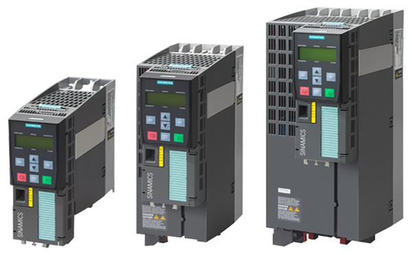
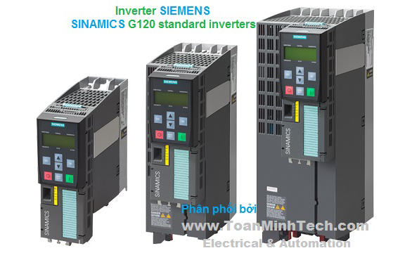
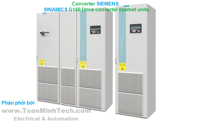
With its SINAMICS G180 cabinet units, Siemens is offering a drive system on which all line-side and motor-side components are integrated extremely compactly into a specially designed cabinet enclosure. This approach minimizes the effort and expense required to configure and install them.
SINAMICS G180 cabinet units are available in air-cooled and liquid-cooled versions.
SINAMICS G180 converter cabinet units are available for the following voltages and power ratings:
|
Rated line voltage |
Power |
|---|---|
|
400 V 3 AC |
200 ... 630 kW1) |
|
500 V 3 AC |
250 ... 800 kW1) |
|
690 V 3 AC |
250 ... 6600 kW |
1) Higher outputs available on request.
Global use
SINAMICS G180 converter cabinet units are manufactured in compliance with relevant international standards and regulations, and are therefore suitable for global use (see technical data).
Air-cooled converter cabinet units are equipped with an ingeniously designed, highly efficient air guidance system which is quiet in operation.
These specially designed liquid-cooled versions of the SINAMICS G180 converter cabinet unit are extremely quiet in operation. Closed control cabinets in degree of protection IP54 or higher make these liquid-cooled converters suitable for applications in harsh environmental conditions.
The advantages of the liquid-cooled version as compared to the air-cooled version are as follows:
The most important directives and standards are listed below. These are used as basis for the SINAMICS G180 cabinet units and they must be carefully observed to achieve an EMC-compliant configuration that is safe both functionally and in operation.
|
European directives |
|
|---|---|
|
2006/95/EC |
Low-voltage directive: |
|
2004/108/EC |
EMC Directive: |
|
International and European standards |
|
|
EN 954‑1 |
Safety of machinery – Safety-related parts of control systems; |
|
EN ISO 13849‑1 |
Safety of machinery – Safety-related parts of control systems; |
|
EN 60146‑1‑1 |
Semiconductor converters – General requirements and line-commutated converters |
|
EN 60204‑1 |
Electrical equipment of machines |
|
EN 60529 |
Degrees of protection provided by enclosures (IP code) |
|
EN 61140 |
Protection against electric shock - Common aspects for installation and equipment |
|
EN 61508‑1 |
Functional safety of electrical/electronic/programmable electronic safety-related systems |
|
EN 61800‑2 |
Adjustable speed electrical power drive systems, |
|
EN 61800‑3 |
Adjustable speed electrical power drive systems, |
|
EN 61800-5-1 |
Adjustable speed electrical power drive systems, |
|
EN 61800‑5‑2 |
Adjustable speed electrical power drive systems, |
|
North American standards |
|
|
UL508C1) |
Power conversion equipment |
|
Approvals |
|
|
TÜV NRTL US1) |
Nationally Recognized Testing Laboratory |
1) On request
|
Electrical data |
|||
|---|---|---|---|
|
|
Line voltages |
Type of supply system |
Output ranges |
|
|
230 … 400 … 415 V 3 AC, -15/+10 % |
TN/TT system |
200 ... 630 kW (at 400 V) |
|
|
230 … 500 V 3 AC, -15/+10 % |
TN/TT/IT system |
250 ... 800 kW (at 500 V) |
|
|
400 … 690 V 3 AC, -15/+10 % |
TN/TT/IT system |
250 ... 6000 kW (at 690 V) |
|
Line frequency |
47 … 63 Hz |
||
|
Output frequency |
0 … 250 Hz |
||
|
Voltage rise in motor |
Typ. 500 ... 1000 V/µs, but < 1500 V/µs |
||
|
Pulse number |
6/12/18/24 |
||
|
Typical line harmonics (I) in % of fundamental mode for the 5/7/11/13/17/19/23/25 harmonics, max. |
38/18/8/7/5/4/3/2 |
||
|
Typical line harmonics (I) in % of fundamental mode for the 5/7/11/13/17/19/23/25 harmonics, max. |
1.5/1/6/4/0.5/0.2/2/2 |
||
|
Typical line harmonics (I) in % of fundamental mode for the 5/7/11/13/17/19/23/25 harmonics, max. |
1/0.5/0.5/0.5/4/3.5/0.5/0.5 |
||
|
Typical line harmonics (I) in % of fundamental mode for the 5/7/11/13/17/19/23/25 harmonics, max. |
1/0.5/0.5/0.5/0.5/0.2/2/2 |
||
|
Typical line harmonics (I) in % of fundamental mode for the 5/7/11/13/17/19/23/25 |
4.5/4.7/2.8/1.6/1.2/0.9/0.6/0.5 |
||
|
Overvoltage category |
III to EN 61800‑5‑1 |
||
|
Short Circuit Current Rating (SCCR) |
20 times rated current, but at least 50 kA |
||
|
Control method |
|
||
|
Fixed speeds |
3 fixed speeds + 1 minimum speed, parameterizable |
||
|
Skipped speed ranges |
2, parameterizable |
||
|
Setpoint resolution |
13 bits digital with n/f setpoint, 12 bits digital with U/I torque setpoint, 9 bits + sign analog |
||
|
Braking operation |
The oversaturation control system makes it possible to generate a braking torque of up to 50 % at low to mid-range speeds, and of up to 10 % at high speeds. If a higher braking torque is required, an optionally available braking module with appropriate braking resistor must be installed. |
||
|
Mechanical data |
|||
|
Degree of protection |
IP21 (higher degrees of protection optionally available) / with liquid cooling IP54 |
||
|
Protection class |
I acc. to EN 61800‑5‑1 |
||
|
Touch protection |
EN 50274 / BGV A3 |
||
|
Type of cooling |
Forced air cooling AF to EN 60146 / Coolant is water and a mixture of water and Antifrogen N with 45 % Antifrogen N |
||
|
Paint finish |
RAL 7035; Rittal TS8 cabinet frame: With nano-ceramic and anodized coating, layer thickness approx. 10 to 20 µm; parts mounted on TS8 cabinet: With nano-ceramic and anodized coating, layer thickness approx. 10 to 20 µm, plus layer of hybrid polyester epoxy powder, thickness approx. 50 to 80 µm |
||
|
Cable entry |
From below by means of profile clamp (from the top as option) |
||
|
Door hinge and opening angle |
Right/130° |
||
|
For liquid-cooled units only |
|||
|
Coolant quality |
See below under "Permissible substance values for the coolant" |
||
|
Permissible coolant temperature |
+10 °C … 28/30/35 °C (dependent on output, see technical data) |
||
|
Ambient conditions2) |
Storage 3) |
Transport 3) |
Operation |
|
Ambient temperature |
-25 … +70 °C |
-25 ... +70 °C |
Air: 0 … 40 °C/ |
|
Relative humidity |
5 ... 95 % |
5 … 95 % |
5 … 95 % |
|
Environmental class/harmful chemical substances |
Class 1C2 acc. to EN 60721‑3‑1 |
Class 2C2 acc. to EN 60721‑3‑2 |
Class 3C2 acc. to EN 60721‑3‑3 |
|
Organic/biological influences |
Class 1B1 acc. to EN 60721‑3‑1 |
Class 2B1 acc. to EN 60721‑3‑2 |
Class 3B1 acc. to EN 60721‑3‑3 |
|
Pollution degree |
2 acc. to EN 61800‑5‑1 |
||
|
Installation altitude |
Up to 1000 m above sea level without derating, > 1000 m see derating data |
||
|
Mechanical stability2) |
Storage 3) |
Transport 3) |
Operation |
|
Vibratory load
|
1.5 mm at 5 … 9 Hz 5 m/s2 at > 9 … 200 Hz |
3.5 mm at 5 … 9 Hz 10 m/s2 at > 9 …200 Hz |
0.075 mm at 10 … 57 Hz 10 m/s2 at > 57 … 150 Hz |
|
Shock load
|
40 m/s2 at 22 ms |
100 m/s2 at 11 ms |
100 m/s2 at 11 ms |
|
Compliance with standards |
|||
|
CE Label |
Acc. to EMC Directive No. 2004/108/EC and Low-Voltage Directive No. 2006/95/EC |
||
|
Radio interference suppression |
Complies with EMC guidelines defined in EN 61800‑3 thanks to line filter which is integrated as standard with grounded supply system:
|
||
|
Approvals |
TÜV NRTL US2) |
||
1) On request
2) Higher standards on request
3) In transport packaging
Deviations from the specified classes are underlined.
The following table lists the permissible substance values for the cooling water (service water and demineralized water) for cooling the converter with an open standard cooling system without cooling unit.
|
Permissible values for SINAMICS G180 cabinet units |
|
|---|---|
|
Coolant temperature |
+10 … 28/30/35 °C |
|
pH value |
7 … 8 |
|
Total hardness |
6 … 20 °dH |
|
Carbonate hardness |
3 … 10 dH |
|
Total dissolved solids 105 °C |
< 500 mg/l |
|
Free carbon dioxide |
< 1 mmol/l |
|
Chlorides |
< 150 mg/l |
|
Sulfates |
500 mg/l |
|
Nitrates |
< 10 mg/l |
|
Nitrites |
0 mg/l |
|
Phosphates |
< 0.5 mg/l |
|
Ammonium NH4 |
< 0.5 mg/l |
|
Ammoniac |
0 mg/l |
|
Silicon (SiO2 crystalline) |
< 10 mg/l |
|
Free CO2 (p value) |
< 15 mg/l |
|
Iron |
< 0.2 mg/l |
|
Hydrogen sulfide |
< 1 mg/l |
|
Suspended solids < 50 μm |
< 10 mg/l |
|
Conductivity |
< 3000 μS/cm |
|
Oxygen |
8 … 12 mg/l |
We recommend the agent "Antifrogen N" supplied by Clariant as a cooling water additive.
The appropriate level of anti-freeze protection can be provided by choosing the correct mixing ratio. A minimum concentration of 20 % by volume provides anti-freeze protection down to ‑10 °C. An Antifrogen/water mixing ratio of 1:2 provides anti-freeze protection down to ‑20 °C.
Unpolluted water mixed with a minimum concentration of 20 % by volume of Antifrogen N prevents the growth of microorganisms and the formation of algae.
|
Line voltage, supply system type |
|
400, 415 V 3 AC TT/TN |
|
|
||
|---|---|---|---|---|---|---|
|
SINAMICS G180 |
|
6SE0180‑ |
6SE0180‑ |
6SE0180‑ |
6SE0180‑ |
6SE0180‑ |
|
Converter type (air-cooled) |
2T3A‑ |
2T3A‑ |
2T3A‑ |
2T3A‑ |
2T3A‑ |
|
|
SINAMICS G180 |
6SE0170‑ |
6SE0170‑ |
6SE0170‑ |
6SE0170‑ |
6SE0170‑ |
|
|
Converter type (liquid-cooled) |
2T6A‑ |
2T6A‑ |
2T6A‑ |
2T6A‑ |
2T6A‑ |
|
|
Electrical data at motor end |
||||||
|
Type rating 1) |
|
|
|
|
|
|
|
kW |
200 |
250 |
315 |
400 |
500 |
|
hp |
268 |
335 |
422 |
536 |
671 |
|
Output voltage2) |
V |
0 ... 0.98 × Vline |
0 ... 0.98 × Vline |
0 ... 0.98 × Vline |
0 ... 0.98 × Vline |
0 ... 0.98 × Vline |
|
Output current |
|
|
|
|
|
|
|
A |
380 |
460 |
630 |
740 |
910 |
|
A |
470 |
560 |
700 |
900 |
1110 |
|
Overload capability |
% |
24 |
22 |
11 |
22 |
22 |
|
Output power |
kVA |
263 |
319 |
436 |
513 |
630 |
|
Output frequency, max. |
Hz |
250 |
250 |
250 |
120 |
120 |
|
Rated clock cycle |
kHz |
3 |
3 |
3 |
2.4 |
2.4 |
|
adjustable from |
kHz |
2 ... 5 |
2 ... 5 |
2 ... 5 |
1.5 ... 3.7 |
1.5 ... 3.7 |
|
Power loss 3) |
kW |
5.6 |
6.42 |
8.4 |
11.9 |
14.9 |
|
Rated efficiency |
% |
97.4 |
97.6 |
97.5 |
97.2 |
97.2 |
|
Electrical data at line end |
||||||
|
Connected load |
kVA |
249 |
300 |
403 |
476 |
603 |
|
Rated input voltage |
V |
400 |
400 |
400 |
400 |
400 |
|
Input current |
|
|
|
|
|
|
|
A |
360 |
433 |
582 |
687 |
871 |
|
A |
445 |
527 |
647 |
836 |
1062 |
|
Line fuse (provided by customer) |
gL (A) |
400 |
500 |
630 |
800 |
900 |
|
λline |
|
0.931 |
0.928 |
0.943 |
0.942 |
0.946 |
|
Cos φline |
|
1 |
1 |
1 |
1 |
1 |
|
Radio interference suppression acc. to EN 61800‑3 |
|
C3 (class A filter) |
C3 (class A filter) |
C3 (class A filter) |
C3 (class A filter) |
C3 (class A filter) |
|
Mechanical data for air-cooled cabinet units |
||||||
|
Frame size (dimensional drawing classification) |
SL2 |
SL2 |
SL2 |
SL21 |
SL3 |
|
|
Sound pressure level LpA |
|
|
|
|
|
|
|
(1 m) at 50/60 Hz |
dB |
70 |
70 |
73 |
75 |
75 |
|
Standard converter dimensions |
|
|
|
|
|
|
|
mm |
806 |
806 |
806 |
1206 |
1606 |
|
mm |
2112 |
2112 |
2112 |
2112 |
2112 |
|
mm |
605 |
605 |
605 |
605 |
605 |
|
Coolant requirements |
m3/h |
1900 |
1900 |
1900 |
2250 |
3800 |
|
Weight, approx. |
kg |
490 |
510 |
530 |
780 |
890 |
|
Mechanical data for liquid-cooled cabinet units |
||||||
|
Frame size (dimensional drawing classification) |
SW2 |
SW2 |
SW2 |
SW21 |
SW3 |
|
|
Sound pressure level LpA |
|
|
|
|
|
|
|
(1 m) at 50/60 Hz |
dB |
68 |
68 |
71 |
73 |
73 |
|
Standard converter dimensions6) |
|
|
|
|
|
|
|
mm |
806 |
806 |
806 |
1206 |
1806 |
|
mm |
2202 |
2202 |
2202 |
2202 |
2202 |
|
mm |
605 |
605 |
605 |
605 |
605 |
|
Coolant requirements |
l/h |
1200 |
1200 |
1200 |
1200 |
2000 |
|
Min. coolant pressure |
bar |
2.5 |
2.5 |
2.5 |
2.5 |
2.5 |
|
Max. coolant pressure |
bar |
6 |
6 |
6 |
6 |
6 |
|
Coolant test pressure |
bar |
10 |
10 |
10 |
10 |
10 |
|
Coolant pressure loss |
bar |
1.9 |
1.9 |
1.9 |
1.9 |
1.9 |
|
Min. coolant temperature |
°C |
10 |
10 |
10 |
10 |
10 |
|
Max. coolant temperature |
°C |
35 |
35 |
35 |
30 |
35 |
|
Weight, approx. |
kg |
490 |
510 |
530 |
860 |
920 |
|
General mechanical data |
||||||
|
Max. cable length between converter and motor with standard insulation |
|
|
|
|
|
|
|
(shielded) |
m |
3005) |
3005) |
3005) |
3005) |
3005) |
|
Line/load connection |
|
|
|
|
|
|
|
L1, L2, L3/U2, V2, W2 |
|
|
|
|
|
|
|
For connection cross-sections, see "Cable cross-sections and connections" in section "Configuring instructions" |
|
|
|
|
|
|
|
Approvals, according to |
|
NRTL6) |
NRTL6) |
NRTL6) |
NRTL6) |
NRTL6) |
1) Rated power of a typical 2- to 6-pole standard motor.
2) Typical output voltage dependent on filter and unit type.
3) Maximum power loss with continuous motor current.
4) With IP21 protective top cover (110 mm).
5) Option L10 included (strengthened dv/dt filter; strengthened filter is integrated in unit).
6) On request.
|
Line voltage, supply system type |
|
400, 415 V 3 AC TT/TN |
|
|
||
|---|---|---|---|---|---|---|
|
SINAMICS G180 |
|
6SE0180‑ |
6SE0180‑ |
|
|
|
|
Converter type (air-cooled) |
2T3A‑ |
2T3A‑ |
||||
|
SINAMICS G180 |
6SE0170‑ |
6SE0170‑ |
|
|
||
|
Converter type (liquid-cooled) |
2T6A‑ |
2T6A‑ |
|
|
|
|
|
Electrical data at motor end |
||||||
|
Type rating 1) |
|
|
|
|
|
|
|
kW |
560 |
630 |
|
|
|
|
hp |
751 |
845 |
|
|
|
|
Output voltage2) |
V |
0 ... 0.98 × Vline |
0 ... 0.98 × Vline |
|
|
|
|
Output current |
|
|
|
|
|
|
|
A |
1020 |
1140 |
|
|
|
|
A |
1230 |
1370 |
|
|
|
|
Overload capability |
% |
21 |
20 |
|
|
|
|
Output power |
kVA |
707 |
790 |
|
|
|
|
Output frequency, max. |
Hz |
120 |
120 |
|
|
|
|
Rated clock cycle |
kHz |
2.4 |
2.4 |
|
|
|
|
adjustable from |
kHz |
1.5 ... 3.7 |
1.5 ... 3.7 |
|
|
|
|
Power loss 3) |
kW |
16.7 |
18.1 |
|
|
|
|
Rated efficiency |
% |
97.2 |
97.3 |
|
|
|
|
Electrical data at line end |
||||||
|
Connected load |
kVA |
676 |
761 |
|
|
|
|
Rated input voltage |
V |
400 |
400 |
|
|
|
|
Input current |
|
|
|
|
|
|
|
A |
975 |
1098 |
|
|
|
|
A |
1176 |
1320 |
|
|
|
|
Line fuse (provided by customer) |
gL (A) |
1000 |
1250 |
|
|
|
|
λline |
|
0.947 |
0.95 |
|
|
|
|
Cos φline |
|
1 |
1 |
|
|
|
|
Radio interference suppression acc. to EN 61800‑3 |
|
C3 (class A filter) |
C3 (class A filter) |
|
|
|
|
Mechanical data for air-cooled cabinet units |
||||||
|
Frame size (dimensional drawing classification) |
SL3 |
SL3 |
||||
|
Sound pressure level LpA |
|
|
|
|
|
|
|
(1 m) at 50/60 Hz |
dB |
75 |
75 |
|
|
|
|
Standard converter dimensions |
|
|
|
|
|
|
|
mm |
1606 |
1606 |
|
|
|
|
mm |
2112 |
2112 |
|
|
|
|
mm |
605 |
605 |
|
|
|
|
Coolant requirements |
m3/h |
3200 |
3800 |
|
|
|
|
Weight, approx. |
kg |
900 |
930 |
|
|
|
|
Mechanical data for liquid-cooled cabinet units |
||||||
|
Frame size (dimensional drawing classification) |
SW3 |
SW3 |
||||
|
Sound pressure level LpA |
|
|
|
|
|
|
|
(1 m) at 50/60 Hz |
dB |
73 |
73 |
|
|
|
|
Standard converter dimensions6) |
|
|
|
|
|
|
|
mm |
1806 |
1806 |
|
|
|
|
mm |
2202 |
2202 |
|
|
|
|
mm |
605 |
605 |
|
|
|
|
Coolant requirements |
l/h |
2000 |
2000 |
|
|
|
|
Min. coolant pressure |
bar |
2.5 |
2.5 |
|
|
|
|
Max. coolant pressure |
bar |
6 |
6 |
|
|
|
|
Coolant test pressure |
bar |
10 |
10 |
|
|
|
|
Coolant pressure loss |
bar |
1.9 |
1.9 |
|
|
|
|
Min. coolant temperature |
°C |
10 |
10 |
|
|
|
|
Max. coolant temperature |
°C |
35 |
35 |
|
|
|
|
Weight, approx. |
kg |
930 |
960 |
|
|
|
|
General mechanical data |
||||||
|
Max. cable length between converter and motor with standard insulation |
|
|
|
|
|
|
|
(shielded) |
m |
3005) |
3005) |
|
|
|
|
Line/load connection |
|
|
|
|
|
|
|
L1, L2, L3/U2, V2, W2 |
|
|
|
|
|
|
|
For connection cross-sections, see "Cable cross-sections and connections" in section "Configuring instructions" |
|
|
|
|
|
|
|
Approvals, according to |
|
NRTL6) |
NRTL6) |
|
|
|
1) Rated power of a typical 2- to 6-pole standard motor.
2) Typical output voltage dependent on filter and unit type.
3) Maximum power loss with continuous motor current.
4) With IP21 protective top cover (110 mm).
5) Option L10 included (strengthened dv/dt filter; strengthened filter is integrated in unit).
6) On request.
|
Line voltage, supply system type |
|
400, 415 V 3 AC IT |
|
|
||
|---|---|---|---|---|---|---|
|
SINAMICS G180 |
|
6SE0180‑ |
6SE0180‑ |
6SE0180‑ |
6SE0180‑ |
6SE0180‑ |
|
Converter type (air-cooled) |
2T3F‑ |
2T3F‑ |
2T3F‑ |
2T3F‑ |
2T3F‑ |
|
|
SINAMICS G180 |
6SE0170‑ |
6SE0170‑ |
6SE0170‑ |
6SE0170‑ |
6SE0170‑ |
|
|
Converter type (liquid-cooled) |
2T6F‑ |
2T6F‑ |
2T6F‑ |
2T6F‑ |
2T6F‑ |
|
|
Electrical data at motor end |
||||||
|
Type rating 1) |
|
|
|
|
|
|
|
kW |
200 |
250 |
315 |
400 |
500 |
|
hp |
268 |
335 |
422 |
536 |
671 |
|
Output voltage2) |
V |
0 ... 0.98 × Vline |
0 ... 0.98 × Vline |
0 ... 0.98 × Vline |
0 ... 0.98 × Vline |
0 ... 0.98 × Vline |
|
Output current |
|
|
|
|
|
|
|
A |
380 |
460 |
630 |
740 |
910 |
|
A |
470 |
560 |
700 |
900 |
1110 |
|
Overload capability |
% |
24 |
22 |
11 |
22 |
22 |
|
Output power |
kVA |
263 |
319 |
436 |
513 |
630 |
|
Output frequency, max. |
Hz |
250 |
250 |
250 |
120 |
120 |
|
Rated clock cycle |
kHz |
3 |
3 |
3 |
2.4 |
2.4 |
|
adjustable from |
kHz |
2 ... 5 |
2 ... 5 |
2 ... 5 |
1.5 ... 3.7 |
1.5 ... 3.7 |
|
Power loss 3) |
kW |
5.6 |
6.42 |
8.4 |
11.9 |
14.9 |
|
Rated efficiency |
% |
97.4 |
97.6 |
97.5 |
97.2 |
97.2 |
|
Electrical data at line end |
||||||
|
Connected load |
kVA |
249 |
301 |
405 |
477 |
604 |
|
Rated input voltage |
V |
400 |
400 |
400 |
400 |
400 |
|
Input current |
|
|
|
|
|
|
|
A |
180 |
217 |
292 |
344 |
436 |
|
A |
223 |
264 |
324 |
418 |
532 |
|
Line fuse (provided by customer) |
gL (A) |
200 |
250 |
400 |
400 |
500 |
|
λline |
|
0.994 |
0.994 |
0.994 |
0.996 |
0.996 |
|
Cos φline |
|
1 |
1 |
1 |
1 |
1 |
|
Radio interference suppression acc. to EN 61800‑3 |
|
C3 (class A filter) |
C3 (class A filter) |
C3 (class A filter) |
C3 (class A filter) |
C3 (class A filter) |
|
Mechanical data for air-cooled cabinet units |
||||||
|
Frame size (dimensional drawing classification) |
SL5 |
SL5 |
SL5 |
SL5 |
SL6 |
|
|
Sound pressure level LpA |
|
|
|
|
|
|
|
(1 m) at 50/60 Hz |
dB |
70 |
70 |
73 |
75 |
75 |
|
Standard converter dimensions |
|
|
|
|
|
|
|
mm |
1406 |
1406 |
1406 |
1406 |
1806 |
|
mm |
2112 |
2112 |
2112 |
2112 |
2112 |
|
mm |
605 |
605 |
605 |
605 |
605 |
|
Coolant requirements |
m3/h |
1900 |
1900 |
1900 |
2250 |
3800 |
|
Weight, approx. |
kg |
690 |
710 |
730 |
810 |
920 |
|
Mechanical data for liquid-cooled cabinet units |
||||||
|
Frame size (dimensional drawing classification) |
SW5 |
SW5 |
SW5 |
SW5 |
SW6 |
|
|
Sound pressure level LpA |
|
|
|
|
|
|
|
(1 m) at 50/60 Hz |
dB |
68 |
68 |
71 |
73 |
73 |
|
Standard converter dimensions |
|
|
|
|
|
|
|
mm |
1406 |
1406 |
1406 |
1406 |
2006 |
|
mm |
2202 |
2202 |
2202 |
2202 |
2202 |
|
mm |
605 |
605 |
605 |
605 |
605 |
|
Coolant requirements |
l/h |
1200 |
1200 |
1200 |
1200 |
2000 |
|
Min. coolant pressure |
bar |
2.5 |
2.5 |
2.5 |
2.5 |
2.5 |
|
Max. coolant pressure |
bar |
6 |
6 |
6 |
6 |
6 |
|
Coolant test pressure |
bar |
10 |
10 |
10 |
10 |
10 |
|
Coolant pressure loss |
bar |
1.9 |
1.9 |
1.9 |
1.9 |
1.9 |
|
Min. coolant temperature |
°C |
10 |
10 |
10 |
10 |
10 |
|
Max. coolant temperature |
°C |
35 |
35 |
35 |
30 |
35 |
|
Weight, approx. |
kg |
690 |
710 |
730 |
810 |
950 |
|
General mechanical data |
||||||
|
Max. cable length between converter and motor with standard insulation |
|
|
|
|
|
|
|
(shielded) |
m |
3005) |
3005) |
3005) |
3005) |
3005) |
|
Line/load connection |
|
|
|
|
|
|
|
L1, L2, L3/U2, V2, W2 |
|
|
|
|
|
|
|
For connection cross-sections, see "Cable cross-sections and connections" in section "Configuring instructions" |
|
|
|
|
|
|
|
Approvals, according to |
|
NRTL6) |
NRTL6) |
NRTL6) |
NRTL6) |
NRTL6) |
1) Rated power of a typical 2- to 6-pole standard motor.
2) Typical output voltage dependent on filter and unit type.
3) Maximum power loss with continuous motor current.
4) With IP21 protective top cover (110 mm).
5) Option L10 included (strengthened dv/dt filter; strengthened filter is integrated in unit).
6) On request.
|
Line voltage, supply system type |
|
400, 415 V 3 AC IT |
||||
|---|---|---|---|---|---|---|
|
SINAMICS G180 |
|
6SE0180‑2BA41‑0❑A7 |
6SE0180‑2BA41‑1❑A7 |
|
|
|
|
Converter type (air-cooled) |
2T3F‑87401‑560 |
2T3F‑87401‑630 |
|
|
|
|
|
SINAMICS G180 |
|
6SE0170‑2BA41‑0❑A7 |
6SE0170‑2BA41‑1❑A7 |
|
|
|
|
Converter type (liquid-cooled) |
2T6F‑77401‑560 |
2T6F‑77401‑630 |
|
|
|
|
|
Electrical data at motor end |
||||||
|
Type rating 1) |
|
|
|
|
|
|
|
kW |
560 |
630 |
|
|
|
|
hp |
751 |
845 |
|
|
|
|
Output voltage2) |
V |
0 ... 0.98 × Vline |
0 ... 0.98 × Vline |
|
|
|
|
Output current |
|
|
|
|
|
|
|
A |
1020 |
1140 |
|
|
|
|
A |
1230 |
1370 |
|
|
|
|
Overload capability |
% |
21 |
20 |
|
|
|
|
Output power |
kVA |
707 |
790 |
|
|
|
|
Output frequency, max. |
Hz |
120 |
120 |
|
|
|
|
Rated clock cycle |
kHz |
2.4 |
2.4 |
|
|
|
|
adjustable from |
kHz |
1.5 ... 3.7 |
1.5 ... 3.7 |
|
|
|
|
Power loss 3) |
kW |
16.7 |
18.1 |
|
|
|
|
Rated efficiency |
% |
97.2 |
97.3 |
|
|
|
|
Electrical data at line end |
||||||
|
Connected load |
kVA |
676 |
762 |
|
|
|
|
Rated input voltage |
V |
400 |
400 |
|
|
|
|
Input current |
|
|
|
|
|
|
|
A |
488 |
550 |
|
|
|
|
A |
588 |
661 |
|
|
|
|
Line fuse (provided by customer) |
gL (A) |
630 |
630 |
|
|
|
|
λline |
|
0.996 |
0.997 |
|
|
|
|
Cos φline |
|
1 |
1 |
|
|
|
|
Radio interference suppression acc. to EN 61800‑3 |
|
C4 |
C4 |
|
|
|
|
Mechanical data for air-cooled cabinet units |
||||||
|
Frame size (dimensional drawing classification) |
SL6 |
SL6 |
||||
|
Sound pressure level LpA |
|
|
|
|
|
|
|
(1 m) at 50/60 Hz |
dB |
75 |
75 |
|
|
|
|
Standard converter dimensions |
|
|
|
|
|
|
|
mm |
1806 |
1806 |
|
|
|
|
mm |
2112 |
2112 |
|
|
|
|
mm |
605 |
605 |
|
|
|
|
Coolant requirements |
m3/h |
3200 |
3800 |
|
|
|
|
Weight, approx. |
kg |
930 |
960 |
|
|
|
|
Mechanical data for liquid-cooled cabinet units |
||||||
|
Frame size (dimensional drawing classification) |
SW6 |
SW6 |
||||
|
Sound pressure level LpA |
|
|
|
|
|
|
|
(1 m) at 50/60 Hz |
dB |
73 |
73 |
|
|
|
|
Standard converter dimensions |
|
|
|
|
|
|
|
mm |
2006 |
2006 |
|
|
|
|
mm |
2202 |
2202 |
|
|
|
|
mm |
605 |
605 |
|
|
|
|
Coolant requirements |
l/h |
2000 |
2000 |
|
|
|
|
Min. coolant pressure |
bar |
2.5 |
2.5 |
|
|
|
|
Max. coolant pressure |
bar |
6 |
6 |
|
|
|
|
Coolant test pressure |
bar |
10 |
10 |
|
|
|
|
Coolant pressure loss |
bar |
1.9 |
1.9 |
|
|
|
|
Min. coolant temperature |
°C |
10 |
10 |
|
|
|
|
Max. coolant temperature |
°C |
35 |
35 |
|
|
|
|
Weight, approx. |
kg |
960 |
990 |
|
|
|
|
General mechanical data |
||||||
|
Max. cable length between converter and motor with standard insulation |
|
|
|
|
|
|
|
(shielded) |
m |
3005) |
3005) |
|
|
|
|
Line/load connection |
|
|
|
|
|
|
|
L1, L2, L3/U2, V2, W2 |
|
|
|
|
|
|
|
For connection cross-sections, see "Cable cross-sections and connections" in section "Configuring instructions" |
|
|
|
|
|
|
|
Approvals, according to |
|
NRTL6) |
NRTL6) |
|
|
|
1) Rated power of a typical 2- to 6-pole standard motor.
2) Typical output voltage dependent on filter and unit type.
3) Maximum power loss with continuous motor current.
4) With IP21 protective top cover (110 mm).
5) Option L10 included (strengthened dv/dt filter; strengthened filter is integrated in unit).
6) On request.
|
Line voltage, supply system type |
|
400, 415, 460, 500 V 3 AC IT/TT/TN |
||||
|---|---|---|---|---|---|---|
|
SINAMICS G180 |
|
6SE0180‑ |
6SE0180‑ |
6SE0180‑ |
6SE0180‑ |
6SE0180‑ |
|
Converter type (air-cooled) |
2T3A‑ |
2T3A‑ |
2T3A‑ |
2T3A‑ |
2T3A‑ |
|
|
SINAMICS G180 |
|
6SE0170‑ |
6SE0170‑ |
6SE0170‑ |
6SE0170‑ |
6SE0170‑ |
|
Converter type (liquid-cooled) |
2T6A‑ |
2T6A‑ |
2T6A‑ |
2T6A‑ |
2T6A‑ |
|
|
Electrical data at motor end |
||||||
|
Type rating 1) |
|
|
|
|
|
|
|
kW |
250 |
315 |
400 |
500 |
560 |
|
hp |
309 |
389 |
494 |
617 |
691 |
|
Output voltage2) |
V |
0 ... 0.98 × Vline |
0 ... 0.98 × Vline |
0 ... 0.98 × Vline |
0 ... 0.98 × Vline |
0 ... 0.98 × Vline |
|
Output current |
|
|
|
|
|
|
|
A |
370 |
460 |
640 |
730 |
820 |
|
A |
450 |
560 |
700 |
900 |
980 |
|
Overload capability |
% |
22 |
22 |
9 |
23 |
20 |
|
Output power |
kVA |
320 |
398 |
554 |
632 |
710 |
|
Output frequency, max. |
Hz |
250 |
250 |
250 |
120 |
120 |
|
Rated clock cycle |
kHz |
3 |
3 |
2.4 |
2.4 |
2.4 |
|
adjustable from |
kHz |
2 ... 5 |
2 ... 5 |
1.5 ... 3.7 |
1.5 ... 3.7 |
1.5 ... 3.7 |
|
Power loss 3) |
kW |
6.15 |
7.39 |
9.37 |
12.8 |
13.7 |
|
Rated efficiency |
% |
97.7 |
97.8 |
97.8 |
97.6 |
97.7 |
|
Electrical data at line end |
||||||
|
Connected load |
kVA |
303 |
378 |
515 |
606 |
678 |
|
Rated input voltage |
V |
500 |
500 |
500 |
500 |
500 |
|
Input current |
|
|
|
|
|
|
|
A |
350 |
437 |
595 |
700 |
783 |
|
A |
426 |
532 |
651 |
863 |
936 |
|
Line fuse (provided by customer) |
gL (A) |
400 |
500 |
630 |
800 |
800 |
|
λline |
|
0.918 |
0.916 |
0.936 |
0.942 |
0.944 |
|
Cos φline |
|
1 |
1 |
1 |
1 |
1 |
|
Radio interference suppression acc. to EN 61800‑34) |
|
C3 (class A filter) |
C3 (class A filter) |
C3 (class A filter) |
C3 (class A filter) |
C3 (class A filter) |
|
Mechanical data for air-cooled cabinet units |
||||||
|
Frame size (dimensional drawing classification) |
SL2 |
SL2 |
SL2 |
SL21 |
SL3 |
|
|
Sound pressure level LpA |
|
|
|
|
|
|
|
(1 m) at 50/60 Hz |
dB |
70 |
73 |
73 |
75 |
75 |
|
Standard converter dimensions |
|
|
|
|
|
|
|
mm |
806 |
806 |
806 |
1206 |
1606 |
|
mm |
2112 |
2112 |
2112 |
2112 |
2112 |
|
mm |
605 |
605 |
605 |
605 |
605 |
|
Coolant requirements |
m3/h |
1900 |
1900 |
1900 |
2250 |
3200 |
|
Weight, approx. |
kg |
490 |
510 |
530 |
780 |
890 |
|
Mechanical data for liquid-cooled cabinet units |
||||||
|
Frame size (dimensional drawing classification) |
SW2 |
SW2 |
SW2 |
SW21 |
SW3 |
|
|
Sound pressure level LpA |
|
|
|
|
|
|
|
(1 m) at 50/60 Hz |
dB |
68 |
71 |
71 |
73 |
73 |
|
Standard converter dimensions |
|
|
|
|
|
|
|
mm |
806 |
806 |
806 |
1206 |
1806 |
|
mm |
2202 |
2202 |
2202 |
2202 |
2202 |
|
mm |
605 |
605 |
605 |
605 |
605 |
|
Coolant requirements |
l/h |
1200 |
1200 |
1200 |
1200 |
2000 |
|
Min. coolant pressure |
bar |
2.5 |
2.5 |
2.5 |
2.5 |
2.5 |
|
Max. coolant pressure |
bar |
6 |
6 |
6 |
6 |
6 |
|
Coolant test pressure |
bar |
10 |
10 |
10 |
10 |
10 |
|
Coolant pressure loss |
bar |
1.9 |
1.9 |
1.9 |
1.9 |
1.9 |
|
Min. coolant temperature |
°C |
10 |
10 |
10 |
10 |
10 |
|
Max. coolant temperature |
°C |
35 |
35 |
35 |
30 |
35 |
|
Weight, approx. |
kg |
490 |
510 |
530 |
850 |
920 |
|
General mechanical data |
||||||
|
Max. cable length between converter and motor with standard insulation |
|
|
|
|
|
|
|
(shielded) |
m |
2506) |
2506) |
2506) |
2506) |
2506) |
|
Line/load connection |
|
|
|
|
|
|
|
L1, L2, L3/U2, V2, W2 |
|
|
|
|
|
|
|
For connection cross-sections, see "Cable cross-sections and connections" in section "Configuring instructions" |
|
|
|
|
|
|
|
Approvals, according to |
|
NRTL7) |
NRTL7) |
NRTL7) |
NRTL7) |
NRTL7) |
1) Rated power of a typical 2- to 6-pole standard motor.
2) Typical output voltage dependent on filter and unit type.
3) Maximum power loss with continuous motor current.
4) EMC filter not required for IT system, in which case RI suppression category C4.
5) With IP21 protective top cover (110 mm).
6) Option L10 included (strengthened dv/dt filter; strengthened filter is integrated in unit).
7) On request.
|
Line voltage, supply system type |
|
400, 415, 460, 500 V 3 AC IT/TT/TN |
|
|
||
|---|---|---|---|---|---|---|
|
SINAMICS G180 |
|
6SE0180‑ |
6SE0180‑ |
6SE0180‑ |
|
|
|
Converter type (air-cooled) |
2T3A‑ |
2T3A‑ |
2T3A‑ |
|||
|
SINAMICS G180 |
|
6SE0170‑ |
6SE0170‑ |
6SE0170‑ |
|
|
|
Converter type (liquid-cooled) |
2T6A‑ |
2T6A‑ |
2T6A‑ |
|||
|
Electrical data at motor end |
||||||
|
Type rating 1) |
|
|
|
|
|
|
|
kW |
630 |
710 |
800 |
|
|
|
hp |
777 |
876 |
987 |
|
|
|
Output voltage2) |
V |
0 ... 0.98 × Vline |
0 ... 0.98 × Vline |
0 ... 0.98 × Vline |
|
|
|
Output current |
|
|
|
|
|
|
|
A |
920 |
1030 |
1150 |
|
|
|
A |
1100 |
1230 |
1380 |
|
|
|
Overload capability |
% |
20 |
19 |
20 |
|
|
|
Output power |
kVA |
797 |
892 |
996 |
|
|
|
Output frequency, max. |
Hz |
120 |
120 |
120 |
|
|
|
Rated clock cycle |
kHz |
2.4 |
2.4 |
2.4 |
|
|
|
adjustable from |
kHz |
1.5 ... 3.7 |
1.5 ... 3.7 |
1.5 ... 3.7 |
|
|
|
Power loss 3) |
kW |
15.4 |
18.1 |
20.3 |
|
|
|
Rated efficiency |
% |
97.7 |
97.6 |
97.6 |
|
|
|
Electrical data at line end |
||||||
|
Connected load |
kVA |
767 |
848 |
944 |
|
|
|
Rated input voltage |
V |
500 |
500 |
500 |
|
|
|
Input current |
|
|
|
|
|
|
|
A |
886 |
979 |
1090 |
|
|
|
A |
1059 |
1169 |
1308 |
|
|
|
Line fuse (provided by customer) |
gL (A) |
900 |
1000 |
1250 |
|
|
|
λline |
|
0.946 |
0.948 |
0.95 |
|
|
|
Cos φline |
|
1 |
1 |
1 |
|
|
|
Radio interference suppression acc. to EN 61800‑34) |
|
C3 (class A filter) |
C3 (class A filter) |
C3 (class A filter) |
|
|
|
Mechanical data for air-cooled cabinet units |
||||||
|
Frame size (dimensional drawing classification) |
SL3 |
SL3 |
SL3 |
|||
|
Sound pressure level LpA |
|
|
|
|
|
|
|
(1 m) at 50/60 Hz |
dB |
75 |
75 |
75 |
|
|
|
Standard converter dimensions |
|
|
|
|
|
|
|
mm |
1606 |
1606 |
1606 |
|
|
|
mm |
2112 |
2112 |
2112 |
|
|
|
mm |
605 |
605 |
605 |
|
|
|
Coolant requirements |
m3/h |
3800 |
3200 |
3800 |
|
|
|
Weight, approx. |
kg |
900 |
930 |
980 |
|
|
|
Mechanical data for liquid-cooled cabinet units |
||||||
|
Frame size (dimensional drawing classification) |
SW3 |
SW3 |
SW3 |
|||
|
Sound pressure level LpA |
|
|
|
|
|
|
|
(1 m) at 50/60 Hz |
dB |
73 |
73 |
73 |
|
|
|
Standard converter dimensions |
|
|
|
|
|
|
|
mm |
1806 |
1806 |
1806 |
|
|
|
mm |
2202 |
2202 |
2202 |
|
|
|
mm |
605 |
605 |
605 |
|
|
|
Coolant requirements |
l/h |
2000 |
2000 |
2000 |
|
|
|
Min. coolant pressure |
bar |
2.5 |
2.5 |
2.5 |
|
|
|
Max. coolant pressure |
bar |
6 |
6 |
6 |
|
|
|
Coolant test pressure |
bar |
10 |
10 |
10 |
|
|
|
Coolant pressure loss |
bar |
1.9 |
1.9 |
1.9 |
|
|
|
Min. coolant temperature |
°C |
10 |
10 |
10 |
|
|
|
Max. coolant temperature |
°C |
35 |
35 |
30 |
|
|
|
Weight, approx. |
kg |
930 |
960 |
1010 |
|
|
|
General mechanical data |
||||||
|
Max. cable length between converter and motor with standard insulation |
|
|
|
|
|
|
|
(shielded) |
m |
2506) |
2506) |
2506) |
|
|
|
Line/load connection |
|
|
|
|
|
|
|
L1, L2, L3/U2, V2, W2 |
|
|
|
|
|
|
|
For connection cross-sections, see "Cable cross-sections and connections" in section "Configuring instructions" |
|
|
|
|
|
|
|
Approvals, according to |
|
NRTL7) |
NRTL7) |
NRTL7) |
|
|
1) Rated power of a typical 2- to 6-pole standard motor.
2) Typical output voltage dependent on filter and unit type.
3) Maximum power loss with continuous motor current.
4) EMC filter not required for IT system, in which case RI suppression category C4.
5) With IP21 protective top cover (110 mm).
6) Option L10 included (strengthened dv/dt filter; strengthened filter is integrated in unit).
7) On request.
|
Line voltage, supply system type |
|
2 × 400, 415, 460, 500 V 3 AC IT |
||||
|---|---|---|---|---|---|---|
|
SINAMICS G180 |
|
6SE0180‑ |
6SE0180‑ |
6SE0180‑ |
6SE0180‑ |
6SE0180‑ |
|
Converter type (air-cooled) |
2T3F‑ |
2T3F‑ |
2T3F‑ |
2T3F‑ |
2T3F‑ |
|
|
SINAMICS G180 |
|
6SE0170‑ |
6SE0170‑ |
6SE0170‑ |
6SE0170‑ |
6SE0170‑ |
|
Converter type (liquid-cooled) |
2T6F‑ |
2T6F‑ |
2T6F‑ |
2T6F‑ |
2T6F‑ |
|
|
Electrical data at motor end |
||||||
|
Type rating 1) |
|
|
|
|
|
|
|
kW |
250 |
315 |
400 |
500 |
560 |
|
hp |
309 |
389 |
494 |
617 |
691 |
|
Output voltage2) |
V |
0 ... 0.98 × Vline |
0 ... 0.98 × Vline |
0 ... 0.98 × Vline |
0 ... 0.98 × Vline |
0 ... 0.98 × Vline |
|
Output current |
|
|
|
|
|
|
|
A |
370 |
460 |
640 |
730 |
820 |
|
A |
450 |
560 |
700 |
900 |
980 |
|
Overload capability |
% |
22 |
22 |
9 |
23 |
20 |
|
Output power |
kVA |
320 |
398 |
554 |
632 |
710 |
|
Output frequency, max. |
Hz |
250 |
250 |
250 |
120 |
120 |
|
Rated clock cycle |
kHz |
3 |
3 |
2.4 |
2.4 |
2.4 |
|
adjustable from |
kHz |
2 ... 5 |
2 ... 5 |
1.5 ... 3.7 |
1.5 ... 3.7 |
1.5 ... 3.7 |
|
Power loss 3) |
kW |
6.15 |
7.39 |
9.37 |
12.8 |
13.7 |
|
Rated efficiency |
% |
97.7 |
97.8 |
97.8 |
97.6 |
97.7 |
|
Electrical data at line end |
||||||
|
Connected load |
kVA |
303 |
378 |
516 |
606 |
677 |
|
Rated input voltage |
V |
2 × 500 |
2 × 500 |
2 × 500 |
2 × 500 |
2 × 500 |
|
Input current |
|
|
|
|
|
|
|
A |
2 × 175 |
2 × 218 |
2 × 298 |
2 × 350 |
2 × 391 |
|
A |
2 × 213 |
2 × 265 |
2 × 326 |
2 × 432 |
2 × 467 |
|
Line fuse (provided by customer) |
gL (A) |
200 |
250 |
400 |
400 |
500 |
|
λline |
|
0.994 |
0.994 |
0.994 |
0.996 |
0.996 |
|
Cos φline |
|
1 |
1 |
1 |
1 |
1 |
|
Radio interference suppression acc. to EN 61800‑3 |
|
C4 |
C4 |
C4 |
C4 |
C4 |
|
Mechanical data for air-cooled cabinet units |
||||||
|
Frame size (dimensional drawing classification) |
SL5 |
SL5 |
SL5 |
SL5 |
SL6 |
|
|
Sound pressure level LpA |
|
|
|
|
|
|
|
(1 m) at 50/60 Hz |
dB |
70 |
73 |
73 |
75 |
75 |
|
Standard converter dimensions |
|
|
|
|
|
|
|
mm |
1406 |
1406 |
1406 |
1406 |
1806 |
|
mm |
2112 |
2112 |
2112 |
2112 |
2112 |
|
mm |
605 |
605 |
605 |
605 |
605 |
|
Coolant requirements |
m3/h |
1900 |
1900 |
1900 |
2250 |
3200 |
|
Weight, approx. |
kg |
690 |
710 |
730 |
810 |
920 |
|
Mechanical data for liquid-cooled cabinet units |
||||||
|
Frame size (dimensional drawing classification) |
SW5 |
SW5 |
SW5 |
SW5 |
SW6 |
|
|
Sound pressure level LpA |
|
|
|
|
|
|
|
(1 m) at 50/60 Hz |
dB |
68 |
71 |
71 |
73 |
73 |
|
Standard converter dimensions |
|
|
|
|
|
|
|
mm |
1406 |
1406 |
1406 |
1406 |
2006 |
|
mm |
2202 |
2202 |
2202 |
2202 |
2202 |
|
mm |
605 |
605 |
605 |
605 |
605 |
|
Coolant requirements |
l/h |
1200 |
1200 |
1200 |
1200 |
2000 |
|
Min. coolant pressure |
bar |
2.5 |
2.5 |
2.5 |
2.5 |
2.5 |
|
Max. coolant pressure |
bar |
6 |
6 |
6 |
6 |
6 |
|
Coolant test pressure |
bar |
10 |
10 |
10 |
10 |
10 |
|
Coolant pressure loss |
bar |
1.9 |
1.9 |
1.9 |
1.9 |
1.9 |
|
Min. coolant temperature |
°C |
10 |
10 |
10 |
10 |
10 |
|
Max. coolant temperature |
°C |
35 |
35 |
35 |
30 |
35 |
|
Weight, approx. |
kg |
690 |
710 |
730 |
810 |
950 |
|
General mechanical data |
||||||
|
Max. cable length between converter and motor with standard insulation |
|
|
|
|
|
|
|
(shielded) |
m |
2505) |
2505) |
2505) |
2505) |
2505) |
|
Line/load connection |
|
|
|
|
|
|
|
L1, L2, L3/U2, V2, W2 |
|
|
|
|
|
|
|
For connection cross-sections, see "Cable cross-sections and connections" in section "Configuring instructions" |
|
|
|
|
|
|
|
Approvals, according to |
|
NRTL6) |
NRTL6) |
NRTL6) |
NRTL6) |
NRTL6) |
1) Rated power of a typical 2- to 6-pole standard motor.
2) Typical output voltage dependent on filter and unit type.
3) Maximum power loss with continuous motor current.
4) With IP21 protective top cover (110 mm).
5) Option L10 included (strengthened dv/dt filter; strengthened filter is integrated in unit).
6) On request.
|
Line voltage, supply system type |
|
2 × 400, 415, 460, 500 V 3 AC IT |
|
|
||
|---|---|---|---|---|---|---|
|
SINAMICS G180 |
|
6SE0180‑ |
6SE0180‑ |
6SE0180‑ |
|
|
|
Converter type (air-cooled) |
2T3F‑ |
2T3F‑ |
2T3F‑ |
|
|
|
|
SINAMICS G180 |
|
6SE0170‑ |
6SE0170‑ |
6SE0170‑ |
|
|
|
Converter type (liquid-cooled) |
2T6F‑ |
2T6F‑ |
2T6F‑ |
|
|
|
|
Electrical data at motor end |
||||||
|
Type rating 1) |
|
|
|
|
|
|
|
kW |
630 |
710 |
800 |
|
|
|
hp |
777 |
876 |
987 |
|
|
|
Output voltage2) |
V |
0 ... 0.98 × Vline |
0 ... 0.98 × Vline |
0 ... 0.98 × Vline |
|
|
|
Output current |
|
|
|
|
|
|
|
A |
920 |
1030 |
1150 |
|
|
|
A |
1100 |
1230 |
1380 |
|
|
|
Overload capability |
% |
20 |
19 |
20 |
|
|
|
Output power |
kVA |
797 |
892 |
996 |
|
|
|
Output frequency, max. |
Hz |
120 |
120 |
120 |
|
|
|
Rated clock cycle |
kHz |
2.4 |
2.4 |
2.4 |
|
|
|
adjustable from |
kHz |
1.5 ... 3.7 |
1.5 ... 3.7 |
1.5 ... 3.7 |
|
|
|
Power loss 3) |
kW |
15.4 |
18.1 |
20.3 |
|
|
|
Rated efficiency |
% |
97.7 |
97.6 |
97.6 |
|
|
|
Electrical data at line end |
||||||
|
Connected load |
kVA |
767 |
849 |
944 |
|
|
|
Rated input voltage |
V |
2 × 500 |
2 × 500 |
2 × 500 |
|
|
|
Input current |
|
|
|
|
|
|
|
A |
2 × 443 |
2 × 490 |
2 × 545 |
|
|
|
A |
2 × 530 |
2 × 585 |
2 × 654 |
|
|
|
Line fuse (provided by customer) |
gL (A) |
500 |
630 |
630 |
|
|
|
λline |
|
0.996 |
0.996 |
0.997 |
|
|
|
Cos φline |
|
1 |
1 |
1 |
|
|
|
Radio interference suppression acc. to EN 61800‑3 |
|
C4 |
C4 |
C4 |
|
|
|
Mechanical data for air-cooled cabinet units |
||||||
|
Frame size (dimensional drawing classification) |
SL6 |
SL6 |
SL6 |
|||
|
Sound pressure level LpA |
|
|
|
|
|
|
|
(1 m) at 50/60 Hz |
dB |
75 |
75 |
75 |
|
|
|
Standard converter dimensions |
|
|
|
|
|
|
|
mm |
1806 |
1806 |
1806 |
|
|
|
mm |
2112 |
2112 |
2112 |
|
|
|
mm |
605 |
605 |
605 |
|
|
|
Coolant requirements |
m3/h |
3800 |
3200 |
3800 |
|
|
|
Weight, approx. |
kg |
930 |
960 |
1010 |
|
|
|
Mechanical data for liquid-cooled cabinet units |
||||||
|
Frame size (dimensional drawing classification) |
SW6 |
SW6 |
SW6 |
|||
|
Sound pressure level LpA |
|
|
|
|
|
|
|
(1 m) at 50/60 Hz |
dB |
73 |
73 |
73 |
|
|
|
Standard converter dimensions |
|
|
|
|
|
|
|
mm |
2006 |
2006 |
2006 |
|
|
|
mm |
2202 |
2202 |
2202 |
|
|
|
mm |
605 |
605 |
605 |
|
|
|
Coolant requirements |
l/h |
2000 |
2000 |
2000 |
|
|
|
Min. coolant pressure |
bar |
2.5 |
2.5 |
2.5 |
|
|
|
Max. coolant pressure |
bar |
6 |
6 |
6 |
|
|
|
Coolant test pressure |
bar |
10 |
10 |
10 |
|
|
|
Coolant pressure loss |
bar |
1.9 |
1.9 |
1.9 |
|
|
|
Min. coolant temperature |
°C |
10 |
10 |
10 |
|
|
|
Max. coolant temperature |
°C |
35 |
35 |
30 |
|
|
|
Weight, approx. |
kg |
960 |
990 |
1040 |
|
|
|
General mechanical data |
||||||
|
Max. cable length between converter and motor with standard insulation |
|
|
|
|
|
|
|
(shielded) |
m |
2505) |
2505) |
2505) |
|
|
|
Line/load connection |
|
|
|
|
|
|
|
L1, L2, L3/U2, V2, W2 |
|
|
|
|
|
|
|
For connection cross-sections, see "Cable cross-sections and connections" in section "Configuring instructions" |
|
|
|
|
|
|
|
Approvals, according to |
|
NRTL6) |
NRTL6) |
NRTL6) |
|
|
1) Rated power of a typical 2- to 6-pole standard motor.
2) Typical output voltage dependent on filter and unit type.
3) Maximum power loss with continuous motor current.
4) With IP21 protective top cover (110 mm).
5) Option L10 included (strengthened dv/dt filter; strengthened filter is integrated in unit).
6) On request
|
Line voltage, supply system type |
|
400, 415, 460, 500, 575, 690 V 3 AC TT/TN or IT |
||||
|---|---|---|---|---|---|---|
|
SINAMICS G180 |
|
6SE0180‑ |
6SE0180‑ |
6SE0180‑ |
6SE0180‑ |
6SE0180‑ |
|
Converter type (air-cooled) |
2T3A‑ |
2T3A‑ |
2T3A‑ |
2T3A‑ |
2T3A‑ |
|
|
SINAMICS G180 |
|
6SE0170‑ |
6SE0170‑ |
6SE0170‑ |
6SE0170‑ |
6SE0170‑ |
|
Converter type (liquid-cooled) |
2T6A‑ |
2T6A‑ |
2T6A‑ |
2T6A‑ |
2T6A‑ |
|
|
Electrical data at motor end |
||||||
|
Type rating 1) |
|
|
|
|
|
|
|
kW |
250 |
315 |
400 |
500 |
560 |
|
hp |
279 |
352 |
447 |
559 |
626 |
|
Output voltage2) |
V |
0 ... 0.98 × Vline |
0 ... 0.98 × Vline |
0 ... 0.98 × Vline |
0 ... 0.98 × Vline |
0 ... 0.98 × Vline |
|
Output current |
|
|
|
|
|
|
|
A |
270 |
340 |
440 |
530 |
590 |
|
A |
320 |
410 |
510 |
640 |
710 |
|
Overload capability |
% |
19 |
21 |
16 |
21 |
20 |
|
Output power |
kVA |
323 |
406 |
526 |
633 |
705 |
|
Output frequency, max. |
Hz |
250 |
250 |
250 |
120 |
120 |
|
Rated clock cycle |
kHz |
3 |
3 |
2.4 |
2.4 |
2.4 |
|
adjustable from |
kHz |
2 ... 5 |
2 ... 5 |
1.5 ... 3.7 |
1.5 ... 3.7 |
1.5 ... 3.7 |
|
Power loss 3) |
kW |
6.15 |
7.73 |
9.37 |
12.2 |
13.7 |
|
Rated efficiency |
% |
97.7 |
97.7 |
97.8 |
97.7 |
97.7 |
|
Electrical data at line end |
||||||
|
Connected load |
kVA |
312 |
391 |
502 |
608 |
676 |
|
Rated input voltage |
V |
690 |
690 |
690 |
690 |
690 |
|
Input current |
|
|
|
|
|
|
|
A |
261 |
327 |
420 |
509 |
566 |
|
A |
309 |
394 |
487 |
615 |
681 |
|
Line fuse (provided by customer) |
gL (A) |
315 |
400 |
500 |
630 |
630 |
|
λline |
|
0.901 |
0.905 |
0.91 |
0.939 |
0.94 |
|
Cos φline |
|
1 |
1 |
1 |
1 |
1 |
|
Radio interference suppression acc. to EN 61800‑34) |
|
C3 (class A filter) |
C3 (class A filter) |
C3 (class A filter) |
C3 (class A filter) |
C3 (class A filter) |
|
Mechanical data for air-cooled cabinet units |
||||||
|
Frame size (dimensional drawing classification) |
SL2 |
SL2 |
SL2 |
SL21 |
SL3 |
|
|
Sound pressure level LpA |
|
|
|
|
|
|
|
(1 m) at 50/60 Hz |
dB |
70 |
70 |
70 |
75 |
75 |
|
Standard converter dimensions |
|
|
|
|
|
|
|
mm |
806 |
806 |
806 |
1206 |
1606 |
|
mm |
2112 |
2112 |
2112 |
2112 |
2112 |
|
mm |
605 |
605 |
605 |
605 |
605 |
|
Coolant requirements |
m3/h |
1900 |
1900 |
1900 |
2650 |
3200 |
|
Weight, approx. |
kg |
490 |
510 |
530 |
780 |
890 |
|
Mechanical data for liquid-cooled cabinet units |
||||||
|
Frame size (dimensional drawing classification) |
SW2 |
SW2 |
SW2 |
SW21 |
SW3 |
|
|
Sound pressure level LpA |
|
|
|
|
|
|
|
(1 m) at 50/60 Hz |
dB |
68 |
68 |
68 |
73 |
73 |
|
Standard converter dimensions |
|
|
|
|
|
|
|
mm |
806 |
806 |
806 |
1206 |
1806 |
|
mm |
2202 |
2202 |
2202 |
2202 |
2202 |
|
mm |
605 |
605 |
605 |
605 |
605 |
|
Coolant requirements |
l/h |
1200 |
1200 |
1200 |
1200 |
2000 |
|
Min. coolant pressure |
bar |
2.5 |
2.5 |
2.5 |
2.5 |
2.5 |
|
Max. coolant pressure |
bar |
6 |
6 |
6 |
6 |
6 |
|
Coolant test pressure |
bar |
10 |
10 |
10 |
10 |
10 |
|
Coolant pressure loss |
bar |
1.9 |
1.9 |
1.9 |
1.9 |
1.9 |
|
Min. coolant temperature |
°C |
10 |
10 |
10 |
10 |
10 |
|
Max. coolant temperature |
°C |
35 |
35 |
35 |
30 |
35 |
|
Weight, approx. |
kg |
490 |
510 |
530 |
850 |
920 |
|
General mechanical data |
||||||
|
Max. cable length between converter and motor with standard insulation |
|
|
|
|
|
|
|
(shielded) |
m |
100/2506) |
100/250 6) |
100/2506) |
100/2506) |
100/2507) |
|
Line/load connection |
|
|
|
|
|
|
|
L1, L2, L3/U2, V2, W2 |
|
|
|
|
|
|
|
For connection cross-sections, see "Cable cross-sections and connections" in section "Configuring instructions" |
|
|
|
|
|
|
|
Approvals, according to |
|
NRTL8) |
NRTL8) |
NRTL8) |
NRTL8) |
NRTL8) |
1) Rated power of a typical 2- to 6-pole standard motor.
2) Typical output voltage dependent on filter and unit type.
3) Maximum power loss with continuous motor current.
4) EMC filter not required for IT system, in which case RI suppression category C4.
5) With IP21 protective top cover (110 mm).
6) Value is applicable with option L10 (strengthened dv/dt filter; filter is integrated in additional 400 mm cabinet).
7) Value is applicable with option L10 (strengthened dv/dt filter; filter is integrated in unit).
8) On request; the voltage range for NRTL units ends at max. 600 V.
|
Line voltage, supply system type |
|
400, 415, 460, 500, 575, 690 V 3 AC TT/TN or IT |
||||
|---|---|---|---|---|---|---|
|
SINAMICS G180 |
|
6SE0180‑ |
6SE0180‑ |
6SE0180‑ |
6SE0180‑ |
6SE0180‑ |
|
Converter type (air-cooled) |
2T3A‑ |
2T3A‑ |
2T3A‑ |
2T3A‑ |
2T3A‑ |
|
|
SINAMICS G180 |
|
6SE0170‑ |
6SE0170‑ |
6SE0170‑ |
6SE0170‑ |
6SE0170‑ |
|
Converter type (liquid-cooled) |
2T6A‑ |
2T6A‑ |
2T6A‑ |
2T6A‑ |
2T6A‑ |
|
|
Electrical data at motor end |
||||||
|
Type rating 1) |
|
|
|
|
|
|
|
kW |
630 |
710 |
800 |
900 |
1000 |
|
hp |
704 |
794 |
894 |
1006 |
1118 |
|
Output voltage2) |
V |
0 ... 0.98 × Vline |
0 ... 0.98 × Vline |
0 ... 0.98 × Vline |
0 ... 0.98 × Vline |
0 ... 0.98 × Vline |
|
Output current |
|
|
|
|
|
|
|
A |
660 |
750 |
840 |
950 |
1040 |
|
A |
800 |
890 |
980 |
1060 |
1130 |
|
Overload capability |
% |
21 |
19 |
17 |
12 |
9 |
|
Output power |
kVA |
789 |
896 |
1004 |
1135 |
1243 |
|
Output frequency, max. |
Hz |
120 |
120 |
120 |
120 |
120 |
|
Rated clock cycle |
kHz |
2.4 |
2.4 |
2.4 |
2.4 |
2.4 |
|
adjustable from |
kHz |
1.5 ... 3.7 |
1.5 ... 3.7 |
1.5 ... 3.7 |
1.5 ... 3.7 |
1.5 ... 3.7 |
|
Power loss 3) |
kW |
15.4 |
16.6 |
18.7 |
21 |
23.3 |
|
Rated efficiency |
% |
97.7 |
97.8 |
97.8 |
97.8 |
97.8 |
|
Electrical data at line end |
||||||
|
Connected load |
kVA |
764 |
854 |
956 |
1078 |
1165 |
|
Rated input voltage |
V |
690 |
690 |
690 |
690 |
690 |
|
Input current |
|
|
|
|
|
|
|
A |
639 |
715 |
800 |
902 |
975 |
|
A |
774 |
848 |
933 |
1006 |
1059 |
|
Line fuse (provided by customer) |
gL (A) |
800 |
800 |
900 |
1000 |
1000 |
|
λline |
|
0.942 |
0.944 |
0.945 |
0.947 |
0.949 |
|
Cos φline |
|
1 |
1 |
1 |
1 |
1 |
|
Radio interference suppression acc. to EN 61800‑34) |
|
C3 (class A filter) |
C3 (class A filter) |
C3 (class A filter) |
C3 (class A filter) |
C3 (class A filter) |
|
Mechanical data for air-cooled cabinet units |
||||||
|
Frame size (dimensional drawing classification) |
SL3 |
SL3 |
SL3 |
SL3 |
SL3 |
|
|
Sound pressure level LpA |
|
|
|
|
|
|
|
(1 m) at 50/60 Hz |
dB |
75 |
75 |
75 |
75 |
75 |
|
Standard converter dimensions |
|
|
|
|
|
|
|
mm |
1606 |
1606 |
1606 |
1606 |
1606 |
|
mm |
2112 |
2112 |
2112 |
2112 |
2112 |
|
mm |
605 |
605 |
605 |
605 |
605 |
|
Coolant requirements |
m3/h |
3200 |
3800 |
3200 |
3800 |
3800 |
|
Weight, approx. |
kg |
890 |
900 |
930 |
980 |
1030 |
|
Mechanical data for liquid-cooled cabinet units |
||||||
|
Frame size (dimensional drawing classification) |
SW3 |
SW3 |
SW3 |
SW3 |
SW3 |
|
|
Sound pressure level LpA |
|
|
|
|
|
|
|
(1 m) at 50/60 Hz |
dB |
73 |
73 |
73 |
73 |
73 |
|
Standard converter dimensions |
|
|
|
|
|
|
|
mm |
1806 |
1806 |
1806 |
1806 |
1806 |
|
mm |
2202 |
2202 |
2202 |
2202 |
2202 |
|
mm |
605 |
605 |
605 |
605 |
605 |
|
Coolant requirements |
l/h |
2000 |
2000 |
2000 |
2000 |
2000 |
|
Min. coolant pressure |
bar |
2.5 |
2.5 |
2.5 |
2.5 |
2.5 |
|
Max. coolant pressure |
bar |
6 |
6 |
6 |
6 |
6 |
|
Coolant test pressure |
bar |
10 |
10 |
10 |
10 |
10 |
|
Coolant pressure loss |
bar |
1.9 |
1.9 |
1.9 |
1.9 |
1.9 |
|
Min. coolant temperature |
°C |
10 |
10 |
10 |
10 |
10 |
|
Max. coolant temperature |
°C |
35 |
35 |
35 |
30 |
28 |
|
Weight, approx. |
kg |
920 |
930 |
960 |
1010 |
1060 |
|
General mechanical data |
||||||
|
Max. cable length between converter and motor with standard insulation |
|
|
|
|
|
|
|
(shielded) |
m |
100/2506) |
100/2506) |
100/2507) |
100/2507) |
100/2507) |
|
Line/load connection |
|
|
|
|
|
|
|
L1, L2, L3/U2, V2, W2 |
|
|
|
|
|
|
|
For connection cross-sections, see "Cable cross-sections and connections" in section "Configuring instructions" |
|
|
|
|
|
|
|
Approvals, according to |
|
NRTL8) |
NRTL8) |
NRTL8) |
NRTL8) |
NRTL8) |
1) Rated power of a typical 2- to 6-pole standard motor.
2) Typical output voltage dependent on filter and unit type.
3) Maximum power loss with continuous motor current.
4) EMC filter not required for IT system, in which case RI suppression category C4.
5) With IP21 protective top cover (110 mm).
6) Value is applicable with option L10 (strengthened dv/dt filter; filter is integrated in unit).
7) Value is applicable with option L10 (strengthened dv/dt filter; filter is integrated in additional 600 mm cabinet).
8) On request; the voltage range for NRTL units ends at max. 600 V.
|
Line voltage, supply system type |
|
400, 415, 460, 500, 575, 690 V 3 AC TT/TN or IT |
||||
|---|---|---|---|---|---|---|
|
SINAMICS G180 |
|
6SE0180‑ |
6SE0180‑ |
6SE0180‑ |
6SE0180‑ |
6SE0180‑ |
|
Converter type (air-cooled) |
2T3A‑ |
2T3A‑ |
2T3A‑ |
2T3A‑ |
2T3A‑ |
|
|
SINAMICS G180 |
|
6SE0170‑ |
6SE0170‑ |
6SE0170‑ |
6SE0170‑ |
6SE0170‑ |
|
Converter type (liquid-cooled) |
2T6A‑ |
2T6A‑ |
2T6A‑ |
2T6A‑ |
2T6A‑ |
|
|
Electrical data at motor end |
||||||
|
Type rating 1) |
|
|
|
|
|
|
|
kW |
1200 |
1300 |
1500 |
1700 |
1900 |
|
hp |
1341 |
1453 |
1676 |
1900 |
2123 |
|
Output voltage2) |
V |
0 ... 0.98 × Vline |
0 ... 0.98 × Vline |
0 ... 0.98 × Vline |
0 ... 0.98 × Vline |
0 ... 0.98 × Vline |
|
Output current |
|
|
|
|
|
|
|
A |
1260 |
1430 |
1600 |
1810 |
1980 |
|
A |
1520 |
1700 |
1870 |
2020 |
2150 |
|
Overload capability |
% |
21 |
19 |
17 |
12 |
9 |
|
Output power |
kVA |
1506 |
1709 |
1912 |
2163 |
2366 |
|
Output frequency, max. |
Hz |
120 |
120 |
120 |
120 |
120 |
|
Rated clock cycle |
kHz |
2.4 |
2.4 |
2.4 |
2.4 |
2.4 |
|
adjustable from |
kHz |
1.5 ... 3.7 |
1.5 ... 3.7 |
1.5 ... 3.7 |
1.5 ... 3.7 |
1.5 ... 3.7 |
|
Power loss 3) |
kW |
28.2 |
33.6 |
37.5 |
42.6 |
46.5 |
|
Rated efficiency |
% |
97.8 |
97.7 |
97.7 |
97.7 |
97.7 |
|
Electrical data at line end |
||||||
|
Connected load |
kVA |
1410 |
1603 |
1795 |
2030 |
2220 |
|
Rated input voltage |
V |
690 |
690 |
690 |
690 |
690 |
|
Input current |
|
|
|
|
|
|
|
A |
1180 |
1341 |
1502 |
1699 |
1858 |
|
A |
1424 |
1594 |
1756 |
1896 |
2018 |
|
Line fuse (provided by customer) |
gL (A) |
1250 |
1500 |
1600 |
1800 |
2000 |
|
λline |
|
0.952 |
0.954 |
0.956 |
0.958 |
0.96 |
|
Cos φline |
|
1 |
1 |
1 |
1 |
1 |
|
Radio interference suppression acc. to EN 61800‑34) |
|
C3 (class A filter) |
C3 (class A filter) |
C3 (class A filter) |
C3 (class A filter) |
C3 (class A filter) |
|
Mechanical data for air-cooled cabinet units |
||||||
|
Frame size (dimensional drawing classification) |
SL4 |
SL4 |
SL4 |
SL4 |
SL4 |
|
|
Sound pressure level LpA |
|
|
|
|
|
|
|
(1 m) at 50/60 Hz |
dB |
77 |
77 |
77 |
77 |
77 |
|
Standard converter dimensions |
|
|
|
|
|
|
|
mm |
3206 |
3206 |
3206 |
3206 |
3206 |
|
mm |
2112 |
2112 |
2112 |
2112 |
2112 |
|
mm |
605 |
605 |
605 |
605 |
605 |
|
Coolant requirements |
m3/h |
6400 |
7600 |
6400 |
7600 |
7600 |
|
Weight, approx. |
kg |
1780 |
1800 |
1860 |
1960 |
2060 |
|
Mechanical data for liquid-cooled cabinet units |
||||||
|
Frame size (dimensional drawing classification) |
SW4 |
SW4 |
SW4 |
SW4 |
SW4 |
|
|
Sound pressure level LpA |
|
|
|
|
|
|
|
(1 m) at 50/60 Hz |
dB |
75 |
75 |
75 |
75 |
75 |
|
Standard converter dimensions |
|
|
|
|
|
|
|
mm |
3606 |
3606 |
3606 |
3606 |
3606 |
|
mm |
2202 |
2202 |
2202 |
2202 |
2202 |
|
mm |
605 |
605 |
605 |
605 |
605 |
|
Coolant requirements |
l/h |
4000 |
4000 |
4000 |
4000 |
4000 |
|
Min. coolant pressure |
bar |
2.5 |
2.5 |
2.5 |
2.5 |
2.5 |
|
Max. coolant pressure |
bar |
6 |
6 |
6 |
6 |
6 |
|
Coolant test pressure |
bar |
10 |
10 |
10 |
10 |
10 |
|
Coolant pressure loss |
bar |
1.9 |
1.9 |
1.9 |
1.9 |
1.9 |
|
Min. coolant temperature |
°C |
10 |
10 |
10 |
10 |
10 |
|
Max. coolant temperature |
°C |
35 |
35 |
35 |
30 |
28 |
|
Weight, approx. |
kg |
1840 |
1860 |
1920 |
2020 |
2120 |
|
General mechanical data |
||||||
|
Max. cable length between converter and motor with standard insulation |
|
|
|
|
|
|
|
(shielded) |
m |
100/2506) |
100/2506) |
100/2507) |
100/2507) |
100/2507) |
|
Line/load connection |
|
|
|
|
|
|
|
L1, L2, L3/U2, V2, W2 |
|
|
|
|
|
|
|
For connection cross-sections, see "Cable cross-sections and connections" in section "Configuring instructions" |
|
|
|
|
|
|
|
Approvals, according to |
|
NRTL8) |
NRTL8) |
NRTL8) |
NRTL8) |
NRTL8) |
1) Rated power of a typical 2- to 6-pole standard motor.
2) Typical output voltage dependent on filter and unit type.
3) Maximum power loss with continuous motor current.
4) EMC filter not required for IT system, in which case RI suppression category C4.
5) With IP21 protective top cover (110 mm).
6) Value is applicable with option L10 (strengthened dv/dt filter; filter is integrated in unit).
7) Value is applicable with option L10 (strengthened dv/dt filter; filter is integrated in additional 2 x 600 mm cabinet).
8) On request; the voltage range for NRTL units ends at max. 600 V.
|
Line voltage, supply system type |
|
2 × 400, 415, 460, 500, 575, 690 V 3 AC IT |
||||
|---|---|---|---|---|---|---|
|
SINAMICS G180 |
|
6SE0180‑ |
6SE0180‑ |
6SE0180‑ |
6SE0180‑ |
6SE0180‑ |
|
Converter type (air-cooled) |
2T3F‑ |
2T3F‑ |
2T3F‑ |
2T3F‑ |
2T3F‑ |
|
|
SINAMICS G180 |
|
6SE0170‑ |
6SE0170‑ |
6SE0170‑ |
6SE0170‑ |
6SE0170‑ |
|
Converter type (liquid-cooled) |
2T6F‑ |
2T6F‑ |
2T6F‑ |
2T6F‑ |
2T6F‑ |
|
|
Electrical data at motor end |
||||||
|
Type rating 1) |
|
|
|
|
|
|
|
kW |
250 |
315 |
400 |
500 |
560 |
|
hp |
279 |
352 |
447 |
559 |
626 |
|
Output voltage2) |
V |
0 ... 0.98 × Vline |
0 ... 0.98 × Vline |
0 ... 0.98 × Vline |
0 ... 0.98 × Vline |
0 ... 0.98 × Vline |
|
Output current |
|
|
|
|
|
|
|
A |
270 |
340 |
440 |
530 |
590 |
|
A |
320 |
410 |
510 |
640 |
710 |
|
Overload capability |
% |
19 |
21 |
16 |
21 |
20 |
|
Output power |
kVA |
323 |
406 |
526 |
633 |
705 |
|
Output frequency, max. |
Hz |
250 |
250 |
250 |
120 |
120 |
|
Rated clock cycle |
kHz |
3 |
3 |
2.4 |
2.4 |
2.4 |
|
adjustable from |
kHz |
2 ... 5 |
2 ... 5 |
1.5 ... 3.7 |
1.5 ... 3.7 |
1.5 ... 3.7 |
|
Power loss 3) |
kW |
6.15 |
7.73 |
9.37 |
12.2 |
13.7 |
|
Rated efficiency |
% |
97.7 |
97.7 |
97.8 |
97.7 |
97.7 |
|
Electrical data at line end |
||||||
|
Connected load |
kVA |
311 |
392 |
502 |
600 |
667 |
|
Rated input voltage |
V |
2 × 690 |
2 × 690 |
2 × 690 |
2 × 690 |
2 × 690 |
|
Input current |
|
|
|
|
|
|
|
A |
2 × 130 |
2 × 164 |
2 × 210 |
2 × 251 |
2 × 279 |
|
A |
2 × 154 |
2 × 198 |
2 × 243 |
2 × 303 |
2 × 336 |
|
Line fuse (provided by customer) |
gL (A) |
160 |
200 |
250 |
315 |
315 |
|
λline |
|
0.995 |
0.995 |
0.995 |
0.997 |
0.997 |
|
Cos φline |
|
1 |
1 |
1 |
1 |
1 |
|
Radio interference suppression acc. to EN 61800‑3 |
|
C4 |
C4 |
C4 |
C4 |
C4 |
|
Mechanical data for air-cooled cabinet units |
||||||
|
Frame size (dimensional drawing classification) |
SL5 |
SL5 |
SL5 |
SL5 |
SL6 |
|
|
Sound pressure level LpA |
|
|
|
|
|
|
|
(1 m) at 50/60 Hz |
dB |
70 |
70 |
70 |
75 |
75 |
|
Standard converter dimensions |
|
|
|
|
|
|
|
mm |
1406 |
1406 |
1406 |
1406 |
1806 |
|
mm |
2112 |
2112 |
2112 |
2112 |
2112 |
|
mm |
605 |
605 |
605 |
605 |
605 |
|
Coolant requirements |
m3/h |
1900 |
1900 |
1900 |
2650 |
3200 |
|
Weight, approx. |
kg |
690 |
710 |
730 |
810 |
920 |
|
Mechanical data for liquid-cooled cabinet units |
||||||
|
Frame size (dimensional drawing classification) |
SW5 |
SW5 |
SW5 |
SW5 |
SW6 |
|
|
Sound pressure level LpA |
|
|
|
|
|
|
|
(1 m) at 50/60 Hz |
dB |
68 |
68 |
68 |
73 |
73 |
|
Standard converter dimensions |
|
|
|
|
|
|
|
mm |
1406 |
1406 |
1406 |
1406 |
2006 |
|
mm |
2202 |
2202 |
2202 |
2202 |
2202 |
|
mm |
605 |
605 |
605 |
605 |
605 |
|
Coolant requirements |
l/h |
1200 |
1200 |
1200 |
1200 |
2000 |
|
Min. coolant pressure |
bar |
2.5 |
2.5 |
2.5 |
2.5 |
2.5 |
|
Max. coolant pressure |
bar |
6 |
6 |
6 |
6 |
6 |
|
Coolant test pressure |
bar |
10 |
10 |
10 |
10 |
10 |
|
Coolant pressure loss |
bar |
1.9 |
1.9 |
1.9 |
1.9 |
1.9 |
|
Min. coolant temperature |
°C |
10 |
10 |
10 |
10 |
10 |
|
Max. coolant temperature |
°C |
35 |
35 |
35 |
30 |
35 |
|
Weight, approx. |
kg |
690 |
710 |
730 |
810 |
950 |
|
General mechanical data |
||||||
|
Max. cable length between converter and motor with standard insulation |
|
|
|
|
|
|
|
(shielded) |
m |
100/2505) |
100/2505) |
100/2505) |
100/2505) |
100/2506) |
|
Line/load connection |
|
|
|
|
|
|
|
L1, L2, L3/U2, V2, W2 |
|
|
|
|
|
|
|
For connection cross-sections, see "Cable cross-sections and connections" in section "Configuring instructions" |
|
|
|
|
|
|
|
Approvals, according to |
|
NRTL7) |
NRTL7) |
NRTL7) |
NRTL7) |
NRTL7) |
1) Rated power of a typical 2- to 6-pole standard motor.
2) Typical output voltage dependent on filter and unit type.
3) Maximum power loss with continuous motor current.
4) With IP21 protective top cover (110 mm).
5) Value is applicable with option L10 (strengthened dv/dt filter; filter is integrated in additional 400 mm cabinet).
6) Value is applicable with option L10 (strengthened dv/dt filter; filter is integrated in unit).
7) On request; the voltage range for NRTL units ends at max. 600 V.
|
Line voltage, supply system type |
|
2 × 400, 415, 460, 500, 575, 690 V 3 AC IT |
||||
|---|---|---|---|---|---|---|
|
SINAMICS G180 |
|
6SE0180‑ |
6SE0180‑ |
6SE0180‑ |
6SE0180‑ |
6SE0180‑ |
|
Converter type (air-cooled) |
2T3F‑ |
2T3F‑ |
2T3F‑ |
2T3F‑ |
2T3F‑ |
|
|
SINAMICS G180 |
|
6SE0170‑ |
6SE0170‑ |
6SE0170‑ |
6SE0170‑ |
6SE0170‑ |
|
Converter type (liquid-cooled) |
2T6F‑ |
2T6F‑ |
2T6F‑ |
2T6F‑ |
2T6F‑ |
|
|
Electrical data at motor end |
||||||
|
Type rating 1) |
|
|
|
|
|
|
|
kW |
630 |
710 |
800 |
900 |
1000 |
|
hp |
704 |
794 |
894 |
1006 |
1118 |
|
Output voltage2) |
V |
0 ... 0.98 × Vline |
0 ... 0.98 × Vline |
0 ... 0.98 × Vline |
0 ... 0.98 × Vline |
0 ... 0.98 × Vline |
|
Output current |
|
|
|
|
|
|
|
A |
660 |
750 |
840 |
950 |
1040 |
|
A |
800 |
890 |
980 |
1060 |
1130 |
|
Overload capability |
% |
21 |
19 |
17 |
12 |
9 |
|
Output power |
kVA |
789 |
896 |
1004 |
1135 |
1243 |
|
Output frequency, max. |
Hz |
120 |
120 |
120 |
120 |
120 |
|
Rated clock cycle |
kHz |
2.4 |
2.4 |
2.4 |
2.4 |
2.4 |
|
adjustable from |
kHz |
1.5 ... 3.7 |
1.5 ... 3.7 |
1.5 ... 3.7 |
1.5 ... 3.7 |
1.5 ... 3.7 |
|
Power loss 3) |
kW |
15.4 |
16.6 |
18.7 |
21 |
23.3 |
|
Rated efficiency |
% |
97.7 |
97.8 |
97.8 |
97.8 |
97.8 |
|
Electrical data at line end |
||||||
|
Connected load |
kVA |
755 |
848 |
949 |
1071 |
1159 |
|
Rated input voltage |
V |
2 × 690 |
2 × 690 |
2 × 690 |
2 × 690 |
2 × 690 |
|
Input current |
|
|
|
|
|
|
|
A |
2 × 316 |
2 × 355 |
2 × 397 |
2 × 448 |
2 × 485 |
|
A |
2 × 383 |
2 × 421 |
2 × 463 |
2 × 500 |
2 × 527 |
|
Line fuse (provided by customer) |
gL (A) |
400 |
400 |
500 |
500 |
630 |
|
λline |
|
0.997 |
0.997 |
0.997 |
0.997 |
0.997 |
|
Cos φline |
|
1 |
1 |
1 |
1 |
1 |
|
Radio interference suppression acc. to EN 61800‑3 |
|
C4 |
C4 |
C4 |
C4 |
C4 |
|
Mechanical data for air-cooled cabinet units |
||||||
|
Frame size (dimensional drawing classification) |
SL6 |
SL6 |
SL6 |
SL6 |
SL6 |
|
|
Sound pressure level LpA |
|
|
|
|
|
|
|
(1 m) at 50/60 Hz |
dB |
75 |
75 |
75 |
75 |
75 |
|
Standard converter dimensions |
|
|
|
|
|
|
|
mm |
1806 |
1806 |
1806 |
1806 |
1806 |
|
mm |
2112 |
2112 |
2112 |
2112 |
2112 |
|
mm |
605 |
605 |
605 |
605 |
605 |
|
Coolant requirements |
m3/h |
3200 |
3800 |
3200 |
3800 |
3800 |
|
Weight, approx. |
kg |
920 |
930 |
960 |
1010 |
1060 |
|
Mechanical data for liquid-cooled cabinet units |
||||||
|
Frame size (dimensional drawing classification) |
SW6 |
SW6 |
SW6 |
SW6 |
SW6 |
|
|
Sound pressure level LpA |
|
|
|
|
|
|
|
(1 m) at 50/60 Hz |
dB |
73 |
73 |
73 |
73 |
73 |
|
Standard converter dimensions |
|
|
|
|
|
|
|
mm |
2006 |
2006 |
2006 |
2006 |
2006 |
|
mm |
2202 |
2202 |
2202 |
2202 |
2202 |
|
mm |
605 |
605 |
605 |
605 |
605 |
|
Coolant requirements |
l/h |
2000 |
2000 |
2000 |
2000 |
2000 |
|
Min. coolant pressure |
bar |
2.5 |
2.5 |
2.5 |
2.5 |
2.5 |
|
Max. coolant pressure |
bar |
6 |
6 |
6 |
6 |
6 |
|
Coolant test pressure |
bar |
10 |
10 |
10 |
10 |
10 |
|
Coolant pressure loss |
bar |
1.9 |
1.9 |
1.9 |
1.9 |
1.9 |
|
Min. coolant temperature |
°C |
10 |
10 |
10 |
10 |
10 |
|
Max. coolant temperature |
°C |
35 |
35 |
35 |
30 |
28 |
|
Weight, approx. |
kg |
950 |
960 |
990 |
1040 |
1090 |
|
General mechanical data |
||||||
|
Max. cable length between converter and motor with standard insulation |
|
|
|
|
|
|
|
(shielded) |
m |
100/2505) |
100/2505) |
100/2506) |
100/2506) |
100/2506) |
|
Line/load connection |
|
|
|
|
|
|
|
L1, L2, L3/U2, V2, W2 |
|
|
|
|
|
|
|
For connection cross-sections, see "Cable cross-sections and connections" in section "Configuring instructions" |
|
|
|
|
|
|
|
Approvals, according to |
|
NRTL7) |
NRTL7) |
NRTL7) |
NRTL7) |
NRTL7) |
1) Rated power of a typical 2- to 6-pole standard motor.
2) Typical output voltage dependent on filter and unit type.
3) Maximum power loss with continuous motor current.
4) With IP21 protective top cover (110 mm).
5) Value is applicable with option L10 (strengthened dv/dt filter; filter is integrated in unit).
6) Value is applicable with option L10 (strengthened dv/dt filter; filter is integrated in additional 600 mm cabinet).
7) On request; the voltage range for NRTL units ends at max. 600 V.
|
Line voltage, supply system type |
|
2 × 400, 415, 460, 500, 575, 690 V 3 AC IT |
||||
|---|---|---|---|---|---|---|
|
SINAMICS G180 |
|
6SE0180‑ |
6SE0180‑ |
6SE0180‑ |
6SE0180‑ |
6SE0180‑ |
|
Converter type (air-cooled) |
2T3F‑ |
2T3F‑ |
2T3F‑ |
2T3F‑ |
2T3F‑ |
|
|
SINAMICS G180 |
|
6SE0170‑ |
6SE0170‑ |
6SE0170‑ |
6SE0170‑ |
6SE0170‑ |
|
Converter type (liquid-cooled) |
2T6F‑ |
2T6F‑ |
2T6F‑ |
2T6F‑ |
2T6F‑ |
|
|
Electrical data at motor end |
||||||
|
Type rating 1) |
|
|
|
|
|
|
|
kW |
1200 |
1300 |
1500 |
1700 |
1900 |
|
hp |
1341 |
1453 |
1676 |
1900 |
2123 |
|
Output voltage2) |
V |
0 ... 0.98 × Vline |
0 ... 0.98 × Vline |
0 ... 0.98 × Vline |
0 ... 0.98 × Vline |
0 ... 0.98 × Vline |
|
Output current |
|
|
|
|
|
|
|
A |
1260 |
1430 |
1600 |
1810 |
1980 |
|
A |
1520 |
1700 |
1870 |
2020 |
2150 |
|
Overload capability |
% |
21 |
19 |
17 |
12 |
9 |
|
Output power |
kVA |
1506 |
1709 |
1912 |
2163 |
2366 |
|
Output frequency, max. |
Hz |
120 |
120 |
120 |
120 |
120 |
|
Rated clock cycle |
kHz |
2.4 |
2.4 |
2.4 |
2.4 |
2.4 |
|
adjustable from |
kHz |
1.5 ... 3.7 |
1.5 ... 3.7 |
1.5 ... 3.7 |
1.5 ... 3.7 |
1.5 ... 3.7 |
|
Power loss 3) |
kW |
28.2 |
33.6 |
37.5 |
42.6 |
46.5 |
|
Rated efficiency |
% |
97.8 |
97.7 |
97.7 |
97.7 |
97.7 |
|
Electrical data at line end |
||||||
|
Connected load |
kVA |
1405 |
1597 |
1781 |
2010 |
2194 |
|
Rated input voltage |
V |
2 × 690 |
2 × 690 |
2 × 690 |
2 × 690 |
2 × 690 |
|
Input current |
|
|
|
|
|
|
|
A |
2 × 588 |
2 × 668 |
2 × 745 |
2 × 841 |
2 × 918 |
|
A |
2 × 709 |
2 × 794 |
2 × 871 |
2 × 939 |
2 × 997 |
|
Line fuse (provided by customer) |
gL (A) |
800 |
800 |
900 |
1000 |
1250 |
|
λline |
|
0.997 |
0.997 |
0.997 |
0.997 |
0.997 |
|
Cos φline |
|
1 |
1 |
1 |
1 |
1 |
|
Radio interference suppression acc. to EN 61800‑3 |
|
C4 |
C4 |
C4 |
C4 |
C4 |
|
Mechanical data for air-cooled cabinet units |
||||||
|
Frame size (dimensional drawing classification) |
SL4 |
SL4 |
SL4 |
SL4 |
SL4 |
|
|
Sound pressure level LpA |
|
|
|
|
|
|
|
(1 m) at 50/60 Hz |
dB |
77 |
77 |
77 |
77 |
77 |
|
Standard converter dimensions |
|
|
|
|
|
|
|
mm |
3206 |
3206 |
3206 |
3206 |
3206 |
|
mm |
2112 |
2112 |
2112 |
2112 |
2112 |
|
mm |
605 |
605 |
605 |
605 |
605 |
|
Coolant requirements |
m3/h |
6400 |
7600 |
6400 |
7600 |
7600 |
|
Weight, approx. |
kg |
1780 |
1800 |
1860 |
1960 |
2060 |
|
Mechanical data for liquid-cooled cabinet units |
||||||
|
Frame size (dimensional drawing classification) |
SW4 |
SW4 |
SW4 |
SW4 |
SW4 |
|
|
Sound pressure level LpA |
|
|
|
|
|
|
|
(1 m) at 50/60 Hz |
dB |
75 |
75 |
75 |
75 |
75 |
|
Standard converter dimensions |
|
|
|
|
|
|
|
mm |
3606 |
3606 |
3606 |
3606 |
3606 |
|
mm |
2202 |
2202 |
2202 |
2202 |
2202 |
|
mm |
605 |
605 |
605 |
605 |
605 |
|
Coolant requirements |
l/h |
4000 |
4000 |
4000 |
4000 |
4000 |
|
Min. coolant pressure |
bar |
2.5 |
2.5 |
2.5 |
2.5 |
2.5 |
|
Max. coolant pressure |
bar |
6 |
6 |
6 |
6 |
6 |
|
Coolant test pressure |
bar |
10 |
10 |
10 |
10 |
10 |
|
Coolant pressure loss |
bar |
1.9 |
1.9 |
1.9 |
1.9 |
1.9 |
|
Min. coolant temperature |
°C |
10 |
10 |
10 |
10 |
10 |
|
Max. coolant temperature |
°C |
35 |
35 |
35 |
30 |
28 |
|
Weight, approx. |
kg |
1840 |
1860 |
1920 |
2020 |
2120 |
|
General mechanical data |
||||||
|
Max. cable length between converter and motor with standard insulation |
|
|
|
|
|
|
|
(shielded) |
m |
100/2505) |
100/2505) |
100/2506) |
100/2506) |
100/2506) |
|
Line/load connection |
|
|
|
|
|
|
|
L1, L2, L3/U2, V2, W2 |
|
|
|
|
|
|
|
For connection cross-sections, see "Cable cross-sections and connections" in section "Configuring instructions" |
|
|
|
|
|
|
|
Approvals, according to |
|
NRTL7) |
NRTL7) |
NRTL7) |
NRTL7) |
NRTL7) |
1) Rated power of a typical 2- to 6-pole standard motor.
2) Typical output voltage dependent on filter and unit type.
3) Maximum power loss with continuous motor current.
4) With IP21 protective top cover (110 mm).
5) Value is applicable with option L10 (strengthened dv/dt filter; filter is integrated in unit).
6) Value is applicable with option L10 (strengthened dv/dt filter; filter is integrated in additional 2 x 600 mm cabinet).
7) On request; the voltage range for NRTL units ends at max. 600 V.
|
Line voltage, supply system type |
|
2 × 400, 415, 460, 500, 575, 690 V 3 AC IT |
||||
|---|---|---|---|---|---|---|
|
SINAMICS G180 |
|
6SE0180‑ |
6SE0180‑ |
6SE0180‑ |
6SE0180‑ |
6SE0180‑ |
|
Converter type (air-cooled) |
2T3F‑ |
2T3F‑ |
2T3F‑ |
2T3F‑ |
2T3F‑ |
|
|
SINAMICS G180 |
|
6SE0170‑ |
6SE0170‑ |
6SE0170‑ |
6SE0170‑ |
6SE0170‑ |
|
Converter type (liquid-cooled) |
2T6F‑ |
2T6F‑ |
2T6F‑ |
2T6F‑ |
2T6F‑ |
|
|
Electrical data at motor end |
||||||
|
Type rating 1) |
|
|
|
|
|
|
|
kW |
2000 |
2300 |
2600 |
2900 |
3100 |
|
hp |
2235 |
2570 |
2906 |
3241 |
3465 |
|
Output voltage2) |
V |
0 ... 0.98 × Vline |
0 ... 0.98 × Vline |
0 ... 0.98 × Vline |
0 ... 0.98 × Vline |
0 ... 0.98 × Vline |
|
Output current |
|
|
|
|
|
|
|
A |
2140 |
2400 |
2710 |
2970 |
3200 |
|
A |
2540 |
2800 |
3030 |
3230 |
3730 |
|
Overload capability |
% |
19 |
17 |
12 |
9 |
17 |
|
Output power |
kVA |
2558 |
2868 |
3239 |
3549 |
3824 |
|
Output frequency, max. |
Hz |
120 |
120 |
120 |
120 |
120 |
|
Rated clock cycle |
kHz |
2.4 |
2.4 |
2.4 |
2.4 |
2.4 |
|
adjustable from |
kHz |
1.5 ... 3.7 |
1.5 ... 3.7 |
1.5 ... 3.7 |
1.5 ... 3.7 |
1.5 ... 3.7 |
|
Power loss 3) |
kW |
50.9 |
57.2 |
64.5 |
73.9 |
77.3 |
|
Rated efficiency |
% |
97.7 |
97.7 |
97.7 |
97.6 |
97.7 |
|
Electrical data at line end |
||||||
|
Connected load |
kVA |
2369 |
2648 |
2983 |
3272 |
3516 |
|
Rated input voltage |
V |
2 × 690 |
2 × 690 |
2 × 690 |
2 × 690 |
2 × 690 |
|
Input current |
|
|
|
|
|
|
|
A |
2 × 991 |
2 × 1108 |
2 × 1248 |
2 × 1369 |
2 × 1471 |
|
A |
2 × 1176 |
2 × 1293 |
2 × 1395 |
2 × 1489 |
2 × 1715 |
|
Line fuse (provided by customer) |
gL (A) |
1250 |
1250 |
1500 |
1600 |
1800 |
|
λline |
|
0.997 |
0.997 |
0.997 |
0.997 |
0.997 |
|
Cos φline |
|
1 |
1 |
1 |
1 |
1 |
|
Radio interference suppression acc. to EN 61800‑3 |
|
C4 |
C4 |
C4 |
C4 |
C4 |
|
Mechanical data for air-cooled cabinet units |
||||||
|
Frame size (dimensional drawing classification) |
SL7 |
SL7 |
SL7 |
SL7 |
SL8 |
|
|
Sound pressure level LpA |
|
|
|
|
|
|
|
(1 m) at 50/60 Hz |
dB |
78 |
78 |
78 |
78 |
79 |
|
Standard converter dimensions |
|
|
|
|
|
|
|
mm |
4806 |
4806 |
4806 |
4806 |
6406 |
|
mm |
2112 |
2112 |
2112 |
2112 |
2112 |
|
mm |
605 |
605 |
605 |
605 |
605 |
|
Coolant requirements |
m3/h |
11400 |
9600 |
11400 |
11400 |
12800 |
|
Weight, approx. |
kg |
2700 |
2790 |
2940 |
3090 |
3720 |
|
Mechanical data for liquid-cooled cabinet units |
||||||
|
Frame size (dimensional drawing classification) |
SW7 |
SW7 |
SW7 |
SW7 |
SW8 |
|
|
Sound pressure level LpA |
|
|
|
|
|
|
|
(1 m) at 50/60 Hz |
dB |
76 |
76 |
76 |
76 |
77 |
|
Standard converter dimensions |
|
|
|
|
|
|
|
mm |
5206 |
5206 |
5206 |
5206 |
7006 |
|
mm |
2202 |
2202 |
2202 |
2202 |
2202 |
|
mm |
605 |
605 |
605 |
605 |
605 |
|
Coolant requirements |
l/h |
6000 |
6000 |
6000 |
6000 |
8000 |
|
Min. coolant pressure |
bar |
2.5 |
2.5 |
2.5 |
2.5 |
2.5 |
|
Max. coolant pressure |
bar |
6 |
6 |
6 |
6 |
6 |
|
Coolant test pressure |
bar |
10 |
10 |
10 |
10 |
10 |
|
Coolant pressure loss |
bar |
1.9 |
1.9 |
1.9 |
1.9 |
1.9 |
|
Min. coolant temperature |
°C |
10 |
10 |
10 |
10 |
10 |
|
Max. coolant temperature |
°C |
35 |
35 |
30 |
28 |
35 |
|
Weight, approx. |
kg |
2750 |
2850 |
2850 |
3100 |
3850 |
|
General mechanical data |
||||||
|
Max. cable length between converter and motor with standard insulation |
|
|
|
|
|
|
|
(shielded) |
m |
100/2505) |
100/2506) |
100/2506) |
100/2506) |
100/2507) |
|
Line/load connection |
|
|
|
|
|
|
|
L1, L2, L3/U2, V2, W2 |
|
|
|
|
|
|
|
For connection cross-sections, see "Cable cross-sections and connections" in section "Configuring instructions" |
|
|
|
|
|
|
|
Approvals, according to |
|
NRTL8) |
NRTL8) |
NRTL8) |
NRTL8) |
NRTL8) |
1) Rated power of a typical 2- to 6-pole standard motor.
2) Typical output voltage dependent on filter and unit type.
3) Maximum power loss with continuous motor current.
4) With IP21 protective top cover (110 mm).
5) Value is applicable with option L10 (strengthened dv/dt filter; filter is integrated in unit).
6) Value is applicable with option L10 (strengthened dv/dt filter; filter is integrated in additional 3 x 600 mm cabinet).
7) Value is applicable with option L10 (strengthened dv/dt filter; filter is integrated in additional 4 x 600 mm cabinet).
8) On request; the voltage range for NRTL units ends at max. 600 V.
|
Line voltage, supply system type |
|
2 × 400, 415, 460, 500, 575, 690 V 3 AC IT |
|
|
|
|
|---|---|---|---|---|---|---|
|
SINAMICS G180 |
|
6SE0180‑2EH43‑6❑A7 |
6SE0180‑2EH44‑0❑A7 |
|
|
|
|
Converter type (air-cooled) |
2T3F‑87604‑935 |
2T3F‑87604‑939 |
||||
|
SINAMICS G180 |
|
6SE0170‑2EH43‑6❑A7 |
6SE0170‑2EH44‑0❑A7 |
|
|
|
|
Converter type (liquid-cooled) |
2T6F‑77604‑935 |
2T6F‑77604‑939 |
||||
|
Electrical data at motor end |
||||||
|
Type rating 1) |
|
|
|
|
|
|
|
kW |
3500 |
3900 |
|
|
|
|
hp |
3912 |
4359 |
|
|
|
|
Output voltage2) |
V |
0 ... 0.98 × Vline |
0 ... 0.98 × Vline |
|
|
|
|
Output current |
|
|
|
|
|
|
|
A |
3610 |
3960 |
|
|
|
|
A |
4030 |
4300 |
|
|
|
|
Overload capability |
% |
12 |
9 |
|
|
|
|
Output power |
kVA |
4314 |
4732 |
|
|
|
|
Output frequency, max. |
Hz |
120 |
120 |
|
|
|
|
Rated clock cycle |
kHz |
2.4 |
2.4 |
|
|
|
|
adjustable from |
kHz |
1.5 ... 3.7 |
1.5 ... 3.7 |
|
|
|
|
Power loss 3) |
kW |
87.3 |
99.7 |
|
|
|
|
Rated efficiency |
% |
97.7 |
97.6 |
|
|
|
|
Electrical data at line end |
||||||
|
Connected load |
kVA |
3956 |
4336 |
|
|
|
|
Rated input voltage |
V |
2 × 690 |
2 × 690 |
|
|
|
|
Input current |
|
|
|
|
|
|
|
A |
2 × 1655 |
2 × 1814 |
|
|
|
|
A |
2 × 1848 |
2 × 1970 |
|
|
|
|
Line fuse (provided by customer) |
gL (A) |
2000 |
2000 |
|
|
|
|
λline |
|
0.997 |
0.997 |
|
|
|
|
Cos φline |
|
1 |
1 |
|
|
|
|
Radio interference suppression acc. to EN 61800‑3 |
|
C4 |
C4 |
|
|
|
|
Mechanical data for air-cooled cabinet units |
||||||
|
Frame size (dimensional drawing classification) |
SL8 |
SL8 |
||||
|
Sound pressure level LpA |
|
|
|
|
|
|
|
(1 m) at 50/60 Hz |
dB |
79 |
79 |
|
|
|
|
Standard converter dimensions |
|
|
|
|
|
|
|
mm |
6406 |
6406 |
|
|
|
|
mm |
2112 |
2112 |
|
|
|
|
mm |
605 |
605 |
|
|
|
|
Coolant requirements |
m3/h |
15200 |
15200 |
|
|
|
|
Weight, approx. |
kg |
3920 |
4120 |
|
|
|
|
Mechanical data for liquid-cooled cabinet units |
||||||
|
Frame size (dimensional drawing classification) |
SW8 |
SW8 |
||||
|
Sound pressure level LpA |
|
|
|
|
|
|
|
(1 m) at 50/60 Hz |
dB |
77 |
77 |
|
|
|
|
Standard converter dimensions |
|
|
|
|
|
|
|
mm |
7006 |
7006 |
|
|
|
|
mm |
2202 |
2202 |
|
|
|
|
mm |
605 |
605 |
|
|
|
|
Coolant requirements |
l/h |
8000 |
8000 |
|
|
|
|
Min. coolant pressure |
bar |
2.5 |
2.5 |
|
|
|
|
Max. coolant pressure |
bar |
6 |
6 |
|
|
|
|
Coolant test pressure |
bar |
10 |
10 |
|
|
|
|
Coolant pressure loss |
bar |
1.9 |
1.9 |
|
|
|
|
Min. coolant temperature |
°C |
10 |
10 |
|
|
|
|
Max. coolant temperature |
°C |
30 |
28 |
|
|
|
|
Weight, approx. |
kg |
4050 |
4250 |
|
|
|
|
General mechanical data |
||||||
|
Max. cable length between converter and motor with standard insulation |
|
|
|
|
|
|
|
(shielded) |
m |
100/2505) |
100/2505) |
|
|
|
|
Line/load connection |
|
|
|
|
|
|
|
L1, L2, L3/U2, V2, W2 |
|
|
|
|
|
|
|
For connection cross-sections, see "Cable cross-sections and connections" in section "Configuring instructions" |
|
|
|
|
|
|
|
Approvals, according to |
|
NRTL6) |
NRTL6) |
|
|
|
1) Rated power of a typical 2- to 6-pole standard motor.
2) Typical output voltage dependent on filter and unit type.
3) Maximum power loss with continuous motor current.
4) With IP21 protective top cover (110 mm).
5) Value is applicable with option L10 (strengthened dv/dt filter; filter is integrated in additional 4 x 600 mm cabinet).
6) On request; the voltage range for NRTL units ends at max. 600 V.
|
Line voltage, supply system type |
|
3 × 400, 415, 460, 500, 575, 690 V 3 AC IT |
||||
|---|---|---|---|---|---|---|
|
SINAMICS G180 |
|
6SE0180‑ |
6SE0180‑ |
6SE0180‑ |
6SE0180‑ |
6SE0180‑ |
|
Converter type (air-cooled) |
2T3K‑ |
2T3K‑ |
2T3K‑ |
2T3K‑ |
2T3K‑ |
|
|
SINAMICS G180 |
|
6SE0170‑ |
6SE0170‑ |
6SE0170‑ |
6SE0170‑ |
6SE0170‑ |
|
Converter type (liquid-cooled) |
2T6K‑ |
2T6K‑ |
2T6K‑ |
2T6K‑ |
2T6K‑ |
|
|
Electrical data at motor end |
||||||
|
Type rating 1) |
|
|
|
|
|
|
|
kW |
2000 |
2300 |
2600 |
2900 |
4100 |
|
hp |
2235 |
2570 |
2906 |
3241 |
4582 |
|
Output voltage2) |
V |
0 ... 0.98 × Vline |
0 ... 0.98 × Vline |
0 ... 0.98 × Vline |
0 ... 0.98 × Vline |
0 ... 0.98 × Vline |
|
Output current |
|
|
|
|
|
|
|
A |
2140 |
2400 |
2710 |
2970 |
4290 |
|
A |
2540 |
2800 |
3030 |
3230 |
5100 |
|
Overload capability |
% |
19 |
17 |
12 |
9 |
19 |
|
Output power |
kVA |
2558 |
2868 |
3239 |
3549 |
5127 |
|
Output frequency, max. |
Hz |
120 |
120 |
120 |
120 |
120 |
|
Rated clock cycle |
kHz |
2.4 |
2.4 |
2.4 |
2.4 |
2.4 |
|
adjustable from |
kHz |
1.5 ... 3.7 |
1.5 ... 3.7 |
1.5 ... 3.7 |
1.5 ... 3.7 |
1.5 ... 3.7 |
|
Power loss 3) |
kW |
50.9 |
57.2 |
64.5 |
73.9 |
102 |
|
Rated efficiency |
% |
97.7 |
97.7 |
97.7 |
97.6 |
97.7 |
|
Electrical data at line end |
||||||
|
Connected load |
kVA |
2369 |
2648 |
2983 |
3272 |
4692 |
|
Rated input voltage |
V |
3 × 690 |
3 × 690 |
3 × 690 |
3 × 690 |
3 × 690 |
|
Input current |
|
|
|
|
|
|
|
A |
3 × 661 |
3 × 739 |
3 × 832 |
3 × 912 |
3 × 1308 |
|
A |
3 × 785 |
3 × 862 |
3 × 930 |
3 × 992 |
3 × 1555 |
|
Line fuse (provided by customer) |
gL (A) |
800 |
900 |
1000 |
1250 |
1500 |
|
λline |
|
1 |
1 |
1 |
1 |
1 |
|
Cos φline |
|
1 |
1 |
1 |
1 |
1 |
|
Radio interference suppression acc. to EN 61800‑3 |
|
C4 |
C4 |
C4 |
C4 |
C4 |
|
Mechanical data for air-cooled cabinet units |
||||||
|
Frame size (dimensional drawing classification) |
SL7 |
SL7 |
SL7 |
SL7 |
SL11 |
|
|
Sound pressure level LpA |
|
|
|
|
|
|
|
(1 m) at 50/60 Hz |
dB |
78 |
78 |
78 |
78 |
79 |
|
Standard converter dimensions |
|
|
|
|
|
|
|
mm |
4806 |
4806 |
4806 |
4806 |
10206 |
|
mm |
2112 |
2112 |
2112 |
2112 |
2112 |
|
mm |
605 |
605 |
605 |
605 |
605 |
|
Coolant requirements |
m3/h |
11400 |
9600 |
11400 |
11400 |
23150 |
|
Weight, approx. |
kg |
2750 |
2840 |
2990 |
3140 |
5750 |
|
Mechanical data for liquid-cooled cabinet units |
||||||
|
Frame size (dimensional drawing classification) |
SW7 |
SW7 |
SW7 |
SW7 |
–5) |
|
|
Sound pressure level LpA |
|
|
|
|
|
|
|
(1 m) at 50/60 Hz |
dB |
76 |
76 |
76 |
76 |
77 |
|
Standard converter dimensions |
|
|
|
|
|
|
|
mm |
5206 |
5206 |
5206 |
5206 |
–5) |
|
mm |
2202 |
2202 |
2202 |
2202 |
–5) |
|
mm |
605 |
605 |
605 |
605 |
–5) |
|
Coolant requirements |
l/h |
6000 |
6000 |
6000 |
6000 |
12000 |
|
Min. coolant pressure |
bar |
2.5 |
2.5 |
2.5 |
2.5 |
2.5 |
|
Max. coolant pressure |
bar |
6 |
6 |
6 |
6 |
6 |
|
Coolant test pressure |
bar |
10 |
10 |
10 |
10 |
10 |
|
Coolant pressure loss |
bar |
1.9 |
1.9 |
1.9 |
1.9 |
1.9 |
|
Min. coolant temperature |
°C |
10 |
10 |
10 |
10 |
10 |
|
Max. coolant temperature |
°C |
35 |
35 |
30 |
28 |
35 |
|
Weight, approx. |
kg |
2830 |
2920 |
3070 |
3220 |
5910 |
|
General mechanical data |
||||||
|
Max. cable length between converter and motor with standard insulation |
|
|
|
|
|
|
|
(shielded) |
m |
100/2506) |
100/2507) |
100/2507) |
100/2507) |
100/2506) |
|
Line/load connection |
|
|
|
|
|
|
|
L1, L2, L3/U2, V2, W2 |
|
|
|
|
|
|
|
For connection cross-sections, see "Cable cross-sections and connections" in section "Configuring instructions" |
|
|
|
|
|
|
|
Approvals, according to |
|
NRTL8) |
NRTL8) |
NRTL8) |
NRTL8) |
NRTL8) |
1) Rated power of a typical 2- to 6-pole standard motor.
2) Typical output voltage dependent on filter and unit type.
3) Maximum power loss with continuous motor current.
4) With IP21 protective top cover (110 mm).
5) Dimensions on request.
6) Value is applicable with option L10 (strengthened dv/dt filter; filter is integrated in unit).
7) Value is applicable with option L10 (strengthened dv/dt filter; filter is integrated in additional 3 x 600 mm cabinet).
8) On request; the voltage range for NRTL units ends at max. 600 V.
|
Line voltage, supply system type |
|
3 × 400, 415, 460, 500, 575, 690 V 3 AC IT |
|
|
||
|---|---|---|---|---|---|---|
|
SINAMICS G180 |
|
6SE0180‑ |
6SE0180‑ |
6SE0180‑ |
|
|
|
Converter type (air-cooled) |
2T3K‑ |
2T3K‑ |
2T3K‑ |
|||
|
SINAMICS G180 |
|
6SE0170‑ |
6SE0170‑ |
6SE0170‑ |
|
|
|
Converter type (liquid-cooled) |
2T6K‑ |
2T6K‑ |
2T6K‑ |
|||
|
Electrical data at motor end |
||||||
|
Type rating 1) |
|
|
|
|
|
|
|
kW |
4700 |
5300 |
5800 |
|
|
|
hp |
5253 |
5923 |
6482 |
|
|
|
Output voltage2) |
V |
0 ... 0.98 × Vline |
0 ... 0.98 × Vline |
0 ... 0.98 × Vline |
|
|
|
Output current |
|
|
|
|
|
|
|
A |
4800 |
5420 |
5940 |
|
|
|
A |
5610 |
6040 |
6450 |
|
|
|
Overload capability |
% |
17 |
11 |
9 |
|
|
|
Output power |
kVA |
5736 |
6477 |
7099 |
|
|
|
Output frequency, max. |
Hz |
120 |
120 |
120 |
|
|
|
Rated clock cycle |
kHz |
2.4 |
2.4 |
2.4 |
|
|
|
adjustable from |
kHz |
1.5 ... 3.7 |
1.5 ... 3.7 |
1.5 ... 3.7 |
|
|
|
Power loss 3) |
kW |
110 |
118 |
129 |
|
|
|
Rated efficiency |
% |
97.8 |
97.9 |
97.9 |
|
|
|
Electrical data at line end |
||||||
|
Connected load |
kVA |
5244 |
5916 |
6482 |
|
|
|
Rated input voltage |
V |
3 × 690 |
3 × 690 |
3 × 690 |
|
|
|
Input current |
|
|
|
|
|
|
|
A |
3 × 1462 |
3 × 1651 |
3 × 1809 |
|
|
|
A |
3 × 1709 |
3 × 1840 |
3 × 1964 |
|
|
|
Line fuse (provided by customer) |
gL (A) |
1800 |
2000 |
2000 ... 2500 |
|
|
|
λline |
|
1 |
1 |
1 |
|
|
|
Cos φline |
|
1 |
1 |
1 |
|
|
|
Radio interference suppression acc. to EN 61800‑3 |
|
C4 |
C4 |
C4 |
|
|
|
Mechanical data for air-cooled cabinet units |
||||||
|
Frame size (dimensional drawing classification) |
SL11 |
SL11 |
SL11 |
|||
|
Sound pressure level LpA |
|
|
|
|
|
|
|
(1 m) at 50/60 Hz |
dB |
79 |
79 |
79 |
|
|
|
Standard converter dimensions |
|
|
|
|
|
|
|
mm |
10206 |
10206 |
10206 |
|
|
|
mm |
2112 |
2112 |
2112 |
|
|
|
mm |
605 |
605 |
605 |
|
|
|
Coolant requirements |
m3/h |
19550 |
23150 |
23150 |
|
|
|
Weight, approx. |
kg |
5930 |
6230 |
6530 |
|
|
|
Mechanical data for liquid-cooled cabinet units |
||||||
|
Frame size (dimensional drawing classification) |
–5) |
–5) |
–5) |
|||
|
Sound pressure level LpA |
|
|
|
|
|
|
|
(1 m) at 50/60 Hz |
dB |
77 |
77 |
77 |
|
|
|
Standard converter dimensions |
|
|
|
|
|
|
|
mm |
–5) |
–5) |
–5) |
|
|
|
mm |
–5) |
–5) |
–5) |
|
|
|
mm |
–5) |
–5) |
–5) |
|
|
|
Coolant requirements |
l/h |
12000 |
12000 |
12000 |
|
|
|
Min. coolant pressure |
bar |
2.5 |
2.5 |
2.5 |
|
|
|
Max. coolant pressure |
bar |
6 |
6 |
6 |
|
|
|
Coolant test pressure |
bar |
10 |
10 |
10 |
|
|
|
Coolant pressure loss |
bar |
1.9 |
1.9 |
1.9 |
|
|
|
Min. coolant temperature |
°C |
10 |
10 |
10 |
|
|
|
Max. coolant temperature |
°C |
38 |
30 |
28 |
|
|
|
Weight, approx. |
kg |
6090 |
6390 |
6690 |
|
|
|
General mechanical data |
||||||
|
Max. cable length between converter and motor with standard insulation |
|
|
|
|
|
|
|
(shielded) |
m |
100/2506) |
100/2506) |
100/2506) |
|
|
|
Line/load connection |
|
|
|
|
|
|
|
L1, L2, L3/U2, V2, W2 |
|
|
|
|
|
|
|
For connection cross-sections, see "Cable cross-sections and connections" in section "Configuring instructions" |
|
|
|
|
|
|
|
Approvals, according to |
|
NRTL7) |
NRTL7) |
NRTL7) |
|
|
1) Rated power of a typical 2- to 6-pole standard motor.
2) Typical output voltage dependent on filter and unit type.
3) Maximum power loss with continuous motor current.
4) With IP21 protective top cover (110 mm).
5) Dimensions on request.
6) Value is applicable with option L10 (strengthened dv/dt filter; filter is integrated in additional 6 x 600 mm cabinet).
7) On request; the voltage range for NRTL units ends at max. 600 V.
|
Line voltage, supply system type |
|
4 × 400, 415, 460, 500, 575, 690 V 3 AC IT |
||||
|---|---|---|---|---|---|---|
|
SINAMICS G180 |
|
6SE0180‑ |
6SE0180‑ |
6SE0180‑ |
6SE0180‑ |
6SE0180‑ |
|
Converter type (air-cooled) |
2T3L‑ |
2T3L‑ |
2T3L‑ |
2T3L‑ |
2T3L‑ |
|
|
SINAMICS G180 |
|
6SE0170‑ |
6SE0170‑ |
6SE0170‑ |
6SE0170‑ |
6SE0170‑ |
|
Converter type (liquid-cooled) |
2T6L‑ |
2T6L‑ |
2T6L‑ |
2T6L‑ |
2T6L‑ |
|
|
Electrical data at motor end |
||||||
|
Type rating 1) |
|
|
|
|
|
|
|
kW |
1200 |
1300 |
1500 |
1700 |
1900 |
|
hp |
1341 |
1453 |
1676 |
1900 |
2123 |
|
Output voltage2) |
V |
0 ... 0.98 × Vline |
0 ... 0.98 × Vline |
0 ... 0.98 × Vline |
0 ... 0.98 × Vline |
0 ... 0.98 × Vline |
|
Output current |
|
|
|
|
|
|
|
A |
1260 |
1430 |
1600 |
1810 |
1980 |
|
A |
1520 |
1700 |
1870 |
2020 |
2150 |
|
Overload capability |
% |
21 |
19 |
17 |
12 |
9 |
|
Output power |
kVA |
1506 |
1709 |
1912 |
2163 |
2366 |
|
Output frequency, max. |
Hz |
120 |
120 |
120 |
120 |
120 |
|
Rated clock cycle |
kHz |
2.4 |
2.4 |
2.4 |
2.4 |
2.4 |
|
adjustable from |
kHz |
1.5 ... 3.7 |
1.5 ... 3.7 |
1.5 ... 3.7 |
1.5 ... 3.7 |
1.5 ... 3.7 |
|
Power loss 3) |
kW |
28.2 |
33.6 |
37.5 |
42.6 |
46.5 |
|
Rated efficiency |
% |
97.8 |
97.7 |
97.7 |
97.7 |
97.7 |
|
Electrical data at line end |
||||||
|
Connected load |
kVA |
1405 |
1597 |
1781 |
2010 |
2194 |
|
Rated input voltage |
V |
4 × 690 |
4 × 690 |
4 × 690 |
4 × 690 |
4 × 690 |
|
Input current |
|
|
|
|
|
|
|
A |
4 × 294 |
4 × 333 |
4 × 372 |
4 × 421 |
4 × 459 |
|
A |
4 × 355 |
4 × 396 |
4 × 435 |
4 × 470 |
4 × 498 |
|
Line fuse (provided by customer) |
gL (A) |
400 |
400 |
500 |
500 |
630 |
|
λline |
|
1 |
1 |
1 |
1 |
1 |
|
Cos φline |
|
1 |
1 |
1 |
1 |
1 |
|
Radio interference suppression acc. to EN 61800‑3 |
|
C4 |
C4 |
C4 |
C4 |
C4 |
|
Mechanical data for air-cooled cabinet units |
||||||
|
Frame size (dimensional drawing classification) |
SL9 |
SL9 |
SL9 |
SL9 |
SL9 |
|
|
Sound pressure level LpA |
|
|
|
|
|
|
|
(1 m) at 50/60 Hz |
dB |
77 |
77 |
77 |
77 |
77 |
|
Standard converter dimensions |
|
|
|
|
|
|
|
mm |
3606 |
3606 |
3606 |
3606 |
3606 |
|
mm |
2112 |
2112 |
2112 |
2112 |
2112 |
|
mm |
605 |
605 |
605 |
605 |
605 |
|
Coolant requirements |
m3/h |
6400 |
7600 |
6400 |
7600 |
7600 |
|
Weight, approx. |
kg |
1830 |
1850 |
1910 |
2010 |
2110 |
|
Mechanical data for liquid-cooled cabinet units |
||||||
|
Frame size (dimensional drawing classification) |
SW9 |
SW9 |
SW9 |
SW9 |
SW9 |
|
|
Sound pressure level LpA |
|
|
|
|
|
|
|
(1 m) at 50/60 Hz |
dB |
75 |
75 |
75 |
75 |
75 |
|
Standard converter dimensions |
|
|
|
|
|
|
|
mm |
4406 |
4406 |
4406 |
4406 |
4406 |
|
mm |
2202 |
2202 |
2202 |
2202 |
2202 |
|
mm |
605 |
605 |
605 |
605 |
605 |
|
Coolant requirements |
l/h |
4000 |
4000 |
4000 |
4000 |
4000 |
|
Min. coolant pressure |
bar |
2.5 |
2.5 |
2.5 |
2.5 |
2.5 |
|
Max. coolant pressure |
bar |
6 |
6 |
6 |
6 |
6 |
|
Coolant test pressure |
bar |
10 |
10 |
10 |
10 |
10 |
|
Coolant pressure loss |
bar |
1.9 |
1.9 |
1.9 |
1.9 |
1.9 |
|
Min. coolant temperature |
°C |
10 |
10 |
10 |
10 |
10 |
|
Max. coolant temperature |
°C |
35 |
35 |
35 |
30 |
28 |
|
Weight, approx. |
kg |
1930 |
1950 |
2010 |
2100 |
2160 |
|
General mechanical data |
||||||
|
Max. cable length between converter and motor with standard insulation |
|
|
|
|
|
|
|
(shielded) |
m |
100/2505) |
100/2505) |
100/2506) |
100/2506) |
100/2506) |
|
Line/load connection |
|
|
|
|
|
|
|
L1, L2, L3/U2, V2, W2 |
|
|
|
|
|
|
|
For connection cross-sections, see "Cable cross-sections and connections" in section "Configuring instructions" |
|
|
|
|
|
|
|
Approvals, according to |
|
NRTL7) |
NRTL7) |
NRTL7) |
NRTL7) |
NRTL7) |
1) Rated power of a typical 2- to 6-pole standard motor.
2) Typical output voltage dependent on filter and unit type.
3) Maximum power loss with continuous motor current.
4) With IP21 protective top cover (110 mm).
5) Value is applicable with option L10 (strengthened dv/dt filter; filter is integrated in unit).
6) Value is applicable with option L10 (strengthened dv/dt filter; filter is integrated in additional 600 mm cabinet).
7) On request; the voltage range for NRTL units ends at max. 600 V.
|
Line voltage, supply system type |
|
4 × 400, 415, 460, 500, 575, 690 V 3 AC IT |
||||
|---|---|---|---|---|---|---|
|
SINAMICS G180 |
|
6SE0180‑ |
6SE0180‑ |
6SE0180‑ |
6SE0180‑ |
6SE0180‑ |
|
Converter type (air-cooled) |
2T3L‑ |
2T3L‑ |
2T3L‑ |
2T3L‑ |
2T3L‑ |
|
|
SINAMICS G180 |
|
6SE0170‑ |
6SE0170‑ |
6SE0170‑ |
6SE0170‑ |
6SE0170‑ |
|
Converter type (liquid-cooled) |
2T6L‑ |
2T6L‑ |
2T6L‑ |
2T6L‑ |
2T6L‑ |
|
|
Electrical data at motor end |
||||||
|
Type rating 1) |
|
|
|
|
|
|
|
kW |
3100 |
3500 |
3900 |
4100 |
4700 |
|
hp |
3465 |
3912 |
4359 |
4582 |
5253 |
|
Output voltage2) |
V |
0 ... 0.98 × Vline |
0 ... 0.98 × Vline |
0 ... 0.98 × Vline |
0 ... 0.98 × Vline |
0 ... 0.98 × Vline |
|
Output current |
|
|
|
|
|
|
|
A |
3200 |
3610 |
3960 |
4290 |
4800 |
|
A |
3730 |
4030 |
4300 |
5100 |
5610 |
|
Overload capability |
% |
17 |
12 |
9 |
19 |
17 |
|
Output power |
kVA |
3824 |
4314 |
4732 |
5127 |
5736 |
|
Output frequency, max. |
Hz |
120 |
120 |
120 |
120 |
120 |
|
Rated clock cycle |
kHz |
2.4 |
2.4 |
2.4 |
2.4 |
2.4 |
|
adjustable from |
kHz |
1.5 ... 3.7 |
1.5 ... 3.7 |
1.5 ... 3.7 |
1.5 ... 3.7 |
1.5 ... 3.7 |
|
Power loss 3) |
kW |
77.3 |
87.3 |
99.7 |
102 |
110 |
|
Rated efficiency |
% |
97.7 |
97.7 |
97.6 |
97.7 |
97.8 |
|
Electrical data at line end |
||||||
|
Connected load |
kVA |
3516 |
3956 |
4336 |
4692 |
5244 |
|
Rated input voltage |
V |
4 × 690 |
4 × 690 |
4 × 690 |
4 × 690 |
4 × 690 |
|
Input current |
|
|
|
|
|
|
|
A |
4 × 735 |
4 × 828 |
4 × 906 |
4 × 982 |
4 × 1098 |
|
A |
4 × 857 |
4 × 924 |
4 × 984 |
4 × 1167 |
4 × 1283 |
|
Line fuse (provided by customer) |
gL (A) |
900 |
1000 |
1000 ... 1250 |
1250 |
1250 ... 1500 |
|
λline |
|
1 |
1 |
1 |
1 |
1 |
|
Cos φline |
|
1 |
1 |
1 |
1 |
1 |
|
Radio interference suppression acc. to EN 61800‑3 |
|
C4 |
C4 |
C4 |
C4 |
C4 |
|
Mechanical data for air-cooled cabinet units |
||||||
|
Frame size (dimensional drawing classification) |
SL10 |
SL10 |
SL10 |
SL12 |
SL12 |
|
|
Sound pressure level LpA |
|
|
|
|
|
|
|
(1 m) at 50/60 Hz |
dB |
79 |
79 |
79 |
79 |
79 |
|
Standard converter dimensions |
|
|
|
|
|
|
|
mm |
7206 |
7206 |
7206 |
11406 |
11406 |
|
mm |
2112 |
2112 |
2112 |
2112 |
2112 |
|
mm |
605 |
605 |
605 |
605 |
605 |
|
Coolant requirements |
m3/h |
12800 |
15200 |
15200 |
23150 |
19550 |
|
Weight, approx. |
kg |
3760 |
3970 |
4170 |
5750 |
5930 |
|
Mechanical data for liquid-cooled cabinet units |
||||||
|
Frame size (dimensional drawing classification) |
SW10 |
SW10 |
SW10 |
–5) |
–5) |
|
|
Sound pressure level LpA |
|
|
|
|
|
|
|
(1 m) at 50/60 Hz |
dB |
77 |
77 |
77 |
77 |
77 |
|
Standard converter dimensions |
|
|
|
|
|
|
|
mm |
7806 |
7806 |
7806 |
–5) |
–5) |
|
mm |
2202 |
2202 |
2202 |
–5) |
–5) |
|
mm |
605 |
605 |
605 |
–5) |
–5) |
|
Coolant requirements |
l/h |
8000 |
8000 |
8000 |
12000 |
12000 |
|
Min. coolant pressure |
bar |
2.5 |
2.5 |
2.5 |
2.5 |
2.5 |
|
Max. coolant pressure |
bar |
6 |
6 |
6 |
6 |
6 |
|
Coolant test pressure |
bar |
10 |
10 |
10 |
10 |
10 |
|
Coolant pressure loss |
bar |
1.9 |
1.9 |
1.9 |
1.9 |
1.9 |
|
Min. coolant temperature |
°C |
10 |
10 |
10 |
10 |
10 |
|
Max. coolant temperature |
°C |
35 |
30 |
28 |
35 |
38 |
|
Weight, approx. |
kg |
3860 |
4070 |
4270 |
5910 |
6090 |
|
General mechanical data |
||||||
|
Max. cable length between converter and motor with standard insulation |
|
|
|
|
|
|
|
(shielded) |
m |
100/2506) |
100/2506) |
100/2506) |
100/2507) |
100/2508) |
|
Line/load connection |
|
|
|
|
|
|
|
L1, L2, L3/U2, V2, W2 |
|
|
|
|
|
|
|
For connection cross-sections, see "Cable cross-sections and connections" in section "Configuring instructions" |
|
|
|
|
|
|
|
Approvals, according to |
|
NRTL9) |
NRTL9) |
NRTL9) |
NRTL9) |
NRTL9) |
1) Rated power of a typical 2- to 6-pole standard motor.
2) Typical output voltage dependent on filter and unit type.
3) Maximum power loss with continuous motor current.
4) With IP21 protective top cover (110 mm).
5) Dimensions on request.
6) With option L10 (strengthened dv/dt filter) the filter is integrated in additional 4 × 600 mm cabinet.
7) Value is applicable with option L10 (strengthened dv/dt filter; filter is integrated in unit).
8) Value is applicable with option L10 (strengthened dv/dt filter; filter is integrated in additional 6 x 600 mm cabinet).
9) On request; the voltage range for NRTL units ends at max. 600 V.
|
Line voltage, supply system type |
|
4 × 400, 415, 460, 500, 575, 690 V 3 AC IT |
|
|
|
|
|---|---|---|---|---|---|---|
|
SINAMICS G180 |
|
6SE0180‑ |
6SE0180‑ |
|
|
|
|
Converter type (air-cooled) |
2T3L‑ |
2T3L‑ |
||||
|
SINAMICS G180 |
|
6SE0170‑ |
6SE0170‑ |
|
|
|
|
Converter type (liquid-cooled) |
2T6L‑ |
2T6L‑ |
||||
|
Electrical data at motor end |
||||||
|
Type rating 1) |
|
|
|
|
|
|
|
kW |
5300 |
5800 |
|
|
|
|
hp |
5923 |
6482 |
|
|
|
|
Output voltage2) |
V |
0 ... 0.98 × Vline |
0 ... 0.98 × Vline |
|
|
|
|
Output current |
|
|
|
|
|
|
|
A |
5420 |
5940 |
|
|
|
|
A |
6040 |
6450 |
|
|
|
|
Overload capability |
% |
11 |
9 |
|
|
|
|
Output power |
kVA |
6477 |
7099 |
|
|
|
|
Output frequency, max. |
Hz |
120 |
120 |
|
|
|
|
Rated clock cycle |
kHz |
2.4 |
2.4 |
|
|
|
|
adjustable from |
kHz |
1.5 ... 3.7 |
1.5 ... 3.7 |
|
|
|
|
Power loss 3) |
kW |
118 |
129 |
|
|
|
|
Rated efficiency |
% |
97.9 |
97.9 |
|
|
|
|
Electrical data at line end |
||||||
|
Connected load |
kVA |
5916 |
6482 |
|
|
|
|
Rated input voltage |
V |
4 × 690 |
4 × 690 |
|
|
|
|
Input current |
|
|
|
|
|
|
|
A |
4 × 1237 |
4 × 1357 |
|
|
|
|
A |
4 × 1378 |
4 × 1474 |
|
|
|
|
Line fuse (provided by customer) |
gL (A) |
1500 |
1500 ... 1800 |
|
|
|
|
λline |
|
1 |
1 |
|
|
|
|
Cos φline |
|
1 |
1 |
|
|
|
|
Radio interference suppression acc. to EN 61800‑3 |
|
C4 |
C4 |
|
|
|
|
Mechanical data for air-cooled cabinet units |
||||||
|
Frame size (dimensional drawing classification) |
SL12 |
SL12 |
||||
|
Sound pressure level LpA |
|
|
|
|
|
|
|
(1 m) at 50/60 Hz |
dB |
79 |
79 |
|
|
|
|
Standard converter dimensions |
|
|
|
|
|
|
|
mm |
11406 |
11406 |
|
|
|
|
mm |
2112 |
2112 |
|
|
|
|
mm |
605 |
605 |
|
|
|
|
Coolant requirements |
m3/h |
23150 |
23150 |
|
|
|
|
Weight, approx. |
kg |
6230 |
6530 |
|
|
|
|
Mechanical data for liquid-cooled cabinet units |
||||||
|
Frame size (dimensional drawing classification) |
–5) |
–5) |
||||
|
Sound pressure level LpA |
|
|
|
|
|
|
|
(1 m) at 50/60 Hz |
dB |
77 |
77 |
|
|
|
|
Standard converter dimensions |
|
|
|
|
|
|
|
mm |
–5) |
–5) |
|
|
|
|
mm |
–5) |
–5) |
|
|
|
|
mm |
–5) |
–5) |
|
|
|
|
Coolant requirements |
l/h |
12000 |
12000 |
|
|
|
|
Min. coolant pressure |
bar |
2.5 |
2.5 |
|
|
|
|
Max. coolant pressure |
bar |
6 |
6 |
|
|
|
|
Coolant test pressure |
bar |
10 |
10 |
|
|
|
|
Coolant pressure loss |
bar |
1.9 |
1.9 |
|
|
|
|
Min. coolant temperature |
°C |
10 |
10 |
|
|
|
|
Max. coolant temperature |
°C |
30 |
28 |
|
|
|
|
Weight, approx. |
kg |
6390 |
6690 |
|
|
|
|
General mechanical data |
||||||
|
Max. cable length between converter and motor with standard insulation |
|
|
|
|
|
|
|
(shielded) |
m |
100/2506) |
100/2506) |
|
|
|
|
Line/load connection |
|
|
|
|
|
|
|
L1, L2, L3/U2, V2, W2 |
|
|
|
|
|
|
|
For connection cross-sections, see "Cable cross-sections and connections" in section "Configuring instructions" |
|
|
|
|
|
|
|
Approvals, according to |
|
NRTL7) |
NRTL7) |
|
|
|
1) Rated power of a typical 2- to 6-pole standard motor.
2) Typical output voltage dependent on filter and unit type.
3) Maximum power loss with continuous motor current.
4) With IP21 protective top cover (110 mm).
5) Dimensions on request.
6) Value is applicable with option L10 (strengthened dv/dt filter; filter is integrated in additional 6 x 600 mm cabinet).
7) On request; the voltage range for NRTL units ends at max. 600 V.
The following tables provide an overview of the options and their availability for SINAMICS G180 cabinet units with a supply voltage of 400 V, 500 V or 690 V. (For details, see catalog chapter 4 "Option descriptions".)
|
|
|
Air-cooled and liquid- |
||||||||||||||
|---|---|---|---|---|---|---|---|---|---|---|---|---|---|---|---|---|
|
|
|
400 V |
500 V |
690 V |
||||||||||||
|
Pulse number |
|
6 |
12 |
6 |
12 |
6 |
12 |
|||||||||
|
Version – see selection and ordering data |
||||||||||||||||
|
Option text |
Additional ordering data -Z with order code and, if necessary, with plain text specification |
A |
B |
C |
D |
E |
F |
G |
H |
I |
J |
K |
L |
M |
N |
O |
|
Line voltages |
||||||||||||||||
|
Line voltage 380 V, 50 Hz |
V70 |
✓ |
✓ |
✓ |
✓ |
✓ |
✓ |
✓ |
✓ |
– |
– |
– |
– |
– |
– |
– |
|
Line voltage 400 V, 50 Hz |
V71 |
❑ |
❑ |
❑ |
❑ |
❑ |
✓ |
✓ |
✓ |
✓ |
✓ |
✓ |
✓ |
✓ |
✓ |
✓ |
|
Line voltage 415 V, 50 Hz |
V72 |
✓ |
✓ |
✓ |
✓ |
✓ |
✓ |
✓ |
✓ |
✓ |
✓ |
✓ |
✓ |
✓ |
✓ |
✓ |
|
Line voltage 500 V, 50 Hz |
V73 |
– |
– |
– |
– |
– |
❑ |
❑ |
❑ |
✓ |
✓ |
✓ |
✓ |
✓ |
✓ |
✓ |
|
Line voltage 660 V, 50 Hz |
V74 |
– |
– |
– |
– |
– |
– |
– |
– |
✓ |
✓ |
✓ |
✓ |
✓ |
✓ |
✓ |
|
Line voltage 690 V, 50 Hz |
V75 |
– |
– |
– |
– |
– |
– |
– |
– |
❑ |
❑ |
❑ |
❑ |
❑ |
❑ |
❑ |
|
Line voltage 440 V, 60 Hz |
V76 |
– |
– |
– |
– |
– |
✓ |
✓ |
✓ |
✓ |
✓ |
✓ |
✓ |
✓ |
✓ |
✓ |
|
Line voltage 460 V, 60 Hz |
V77 |
– |
– |
– |
– |
– |
✓ |
✓ |
✓ |
✓ |
✓ |
✓ |
✓ |
✓ |
✓ |
✓ |
|
Line voltage 480 V, 60 Hz |
V78 |
– |
– |
– |
– |
– |
✓ |
✓ |
✓ |
✓ |
✓ |
✓ |
✓ |
✓ |
✓ |
✓ |
|
Line voltage 600 V, 60 Hz |
V79 |
– |
– |
– |
– |
– |
– |
– |
– |
✓ |
✓ |
✓ |
✓ |
✓ |
✓ |
✓ |
|
Line voltage 660 V, 60 Hz |
V80 |
– |
– |
– |
– |
– |
– |
– |
– |
✓ |
✓ |
✓ |
✓ |
✓ |
✓ |
✓ |
|
Special line voltage; please specify voltage |
Y70 • and identification code |
✓1) |
✓1) |
✓1) |
✓1) |
✓1) |
✓2) |
✓2) |
✓2) |
✓3) |
✓3) |
✓3) |
✓3) |
✓3) |
✓3) |
✓3) |
|
Additional cabinet |
||||||||||||||||
|
400 mm |
H90 |
✓ |
✓ |
✓ |
✓ |
✓ |
✓ |
✓ |
✓ |
✓ |
✓ |
✓ |
✓ |
✓ |
✓ |
✓ |
|
600 mm |
H91 |
✓ |
✓ |
✓ |
✓ |
✓ |
✓ |
✓ |
✓ |
✓ |
✓ |
✓ |
✓ |
✓ |
✓ |
✓ |
|
800 mm |
H92 |
✓ |
✓ |
✓ |
✓ |
✓ |
✓ |
✓ |
✓ |
✓ |
✓ |
✓ |
✓ |
✓ |
✓ |
✓ |
|
1000 mm |
H93 |
✓ |
✓ |
✓ |
✓ |
✓ |
✓ |
✓ |
✓ |
✓ |
✓ |
✓ |
✓ |
✓ |
✓ |
✓ |
|
1200 mm |
H94 |
✓ |
✓ |
✓ |
✓ |
✓ |
✓ |
✓ |
✓ |
✓ |
✓ |
✓ |
✓ |
✓ |
✓ |
✓ |
|
External auxiliary power supply |
||||||||||||||||
|
Connection for 230 V 1 AC 50 Hz auxiliary voltage provided by customer |
C36 |
✓ |
✓ |
✓ |
✓ |
✓ |
✓ |
✓ |
✓ |
✓ |
✓ |
✓ |
✓ |
✓ |
✓ |
✓ |
|
Connection for 400 V 3 AC 50 Hz auxiliary voltage provided by customer |
C38 |
✓ |
✓ |
✓ |
✓ |
✓ |
✓ |
✓ |
✓ |
✓ |
✓ |
✓ |
✓ |
✓ |
✓ |
✓ |
|
Connection for 500 V 3 AC 50 Hz auxiliary voltage provided by customer |
C43 |
✓ |
✓ |
✓ |
✓ |
✓ |
✓ |
✓ |
✓ |
✓ |
✓ |
✓ |
✓ |
✓ |
✓ |
✓ |
|
Connection for 690 V 3 AC 50 Hz auxiliary voltage provided by customer |
C48 |
✓ |
✓ |
✓ |
✓ |
✓ |
✓ |
✓ |
✓ |
✓ |
✓ |
✓ |
✓ |
✓ |
✓ |
✓ |
|
Connection for other 3 AC voltage provided by customer; please specify voltage |
Y36 • and identification code |
✓ |
✓ |
✓ |
✓ |
✓ |
✓ |
✓ |
✓ |
✓ |
✓ |
✓ |
✓ |
✓ |
✓ |
✓ |
|
External control voltage supply |
||||||||||||||||
|
Connection for 230 V 1 AC 50 Hz control voltage provided by customer, without UPS backup |
C56 |
✓ |
✓ |
✓ |
✓ |
✓ |
✓ |
✓ |
✓ |
✓ |
✓ |
✓ |
✓ |
✓ |
✓ |
✓ |
|
Connection for 230 V 1 AC 50 Hz control voltage provided by customer, with UPS backup |
C57 |
✓ |
✓ |
✓ |
✓ |
✓ |
✓ |
✓ |
✓ |
✓ |
✓ |
✓ |
✓ |
✓ |
✓ |
✓ |
|
Connection for different 1 AC control voltage (47 to 63 Hz) provided by customer; please specify voltage |
Y55 • and identification code |
✓ |
✓ |
✓ |
✓ |
✓ |
✓ |
✓ |
✓ |
✓ |
✓ |
✓ |
✓ |
✓ |
✓ |
✓ |
|
Other option |
||||||||||||||||
|
Board for mains supply backup |
E85 |
✓ |
✓ |
✓ |
✓ |
✓ |
✓ |
✓ |
✓ |
✓ |
✓ |
✓ |
✓ |
✓ |
✓ |
✓ |
|
RFI suppression filter |
||||||||||||||||
|
RFI suppression filter, category C2 or C3 (class A) |
L00 |
❑ |
❑ |
❑ |
❑ |
– |
✓ |
✓ |
– |
❑ |
❑ |
❑ |
✓ |
✓ |
✓ |
– |
|
Line Harmonics Filter |
||||||||||||||||
|
Line Harmonics Filter for 50 Hz line frequency |
L03 |
H926) |
H926) |
H936) |
✓5) |
– |
H936) |
✓5) |
– |
H926) |
H936) |
✓5) |
H926) |
H936) |
✓5) |
– |
|
Line Harmonics Filter for 60 Hz line frequency |
L04 |
H926) |
H926) |
H936) |
✓5) |
– |
H936) |
✓5) |
– |
H926) |
H936) |
✓5) |
H926) |
H936) |
✓5) |
– |
|
Output filter |
||||||||||||||||
|
Strengthened dv/dtoutput filter for max. 250/300 m (type-dependent). Design for longer motor cables available on request |
L10 |
❑ |
❑ |
❑ |
❑ |
❑ |
❑ |
❑ |
❑ |
✓4) |
✓4) |
✓4) |
✓4) |
✓4) |
✓4) |
✓4) |
|
Sine-wave filter integrated in control cabinet or additional cabinet, suitable for motor frequencies of ≤ 75 Hz, voltage drop of approximately 10 % of line voltage |
L14 |
H916) |
H926) |
H926) |
H926) |
✓5) |
H916) |
H926) |
✓5) |
– |
– |
– |
– |
– |
– |
– |
|
Sine-wave filter integrated in control cabinet or additional cabinet, suitable for motor frequencies of ≤ 60 Hz, voltage drop of approximately 10 % of line voltage |
L15 |
– |
– |
– |
– |
– |
– |
– |
– |
✓5) |
✓5) |
✓5) |
✓5) |
✓5) |
✓5) |
✓5) |
|
Standard accessories packages |
||||||||||||||||
|
Peripheral board 4 (G05) instead of peripheral board 2 (G03) (only in conjunction with package S01, S02, S03, S04, S08, S09, S11, S12) |
G08 |
✓ |
✓ |
✓ |
✓ |
✓ |
✓ |
✓ |
✓ |
✓ |
✓ |
✓ |
✓ |
✓ |
✓ |
✓ |
|
Accessories package S01 with main switch, line contactor, EMERGENCY OFF pushbutton and safety relay, board G03, local/remote switch |
S01 |
✓ |
✓ |
✓ |
✓ |
✓ |
✓ |
✓ |
✓ |
✓ |
✓ |
✓ |
✓ |
✓ |
✓ |
✓ |
|
Accessories package S02 with circuit breaker, line contactor, EMERGENCY OFF pushbutton and safety relay, board G03, local/remote switch |
S02 |
✓ |
✓ |
✓ |
✓ |
✓ |
✓ |
✓ |
✓ |
✓ |
✓ |
✓ |
✓ |
✓ |
✓ |
✓ |
|
Accessories package with main switch, line contactor, board G03, local/remote switch |
S03 |
✓ |
✓ |
✓ |
✓ |
✓ |
✓ |
✓ |
✓ |
✓ |
✓ |
✓ |
✓ |
✓ |
✓ |
✓ |
|
Accessories package with circuit breaker, line contactor, board G03, local/remote switch |
S04 |
✓ |
✓ |
✓ |
✓ |
✓ |
✓ |
✓ |
✓ |
✓ |
✓ |
✓ |
✓ |
✓ |
✓ |
✓ |
|
Accessories package with main switch, line contactor, Calomat, RCU box connection |
S06 |
✓ |
✓ |
✓ |
✓ |
✓ |
✓ |
✓ |
✓ |
✓ |
✓ |
✓ |
✓ |
✓ |
✓ |
✓ |
|
Bypass for smooth line synchronization (soft start function) incl. line-side main switch and contactors at the converter output and in bypass |
S08 |
H926) |
H926) |
H926) |
H926) |
✓5) |
H926) |
H926) |
✓5) |
H926) |
H926) |
H926) |
✓5) |
✓5) |
✓5) |
✓5) |
|
Bypass for smooth line synchronization (soft start function) incl. line-side circuit breaker and contactors at the converter output and in bypass |
S09 |
H926) |
H926) |
H926) |
H926) |
✓5) |
H926) |
H926) |
✓5) |
H926) |
H926) |
H926) |
✓5) |
✓5) |
✓5) |
✓5) |
|
Accessories package S11 with line-side main switch, board G03, local/remote switch |
S11 |
✓ |
✓ |
✓ |
✓ |
✓ |
✓ |
✓ |
✓ |
✓ |
✓ |
✓ |
✓ |
✓ |
✓ |
✓ |
|
Accessories package S12 with line-side circuit breaker, board G03, local/remote switch |
S12 |
✓ |
✓ |
✓ |
✓ |
✓ |
✓ |
✓ |
✓ |
✓ |
✓ |
✓ |
✓ |
✓ |
✓ |
✓ |
|
Bypass with line-side main switch, contactors at converter output and in bypass, switchover between manual and automatic, local/remote switch |
S21 |
H916) |
H916) |
H916) |
H916) |
✓5) |
H916) |
H916) |
✓5) |
H916) |
H916) |
H916) |
✓5) |
✓5) |
✓5) |
✓5) |
|
Bypass with line-side circuit breaker, contactors at converter output and in bypass, switchover between manual and automatic, local/remote switch |
S22 |
H916) |
H916) |
H916) |
H916) |
✓5) |
H916) |
H916) |
✓5) |
H916) |
H916) |
H916) |
✓5) |
✓5) |
✓5) |
✓5) |
|
Bypass with line-side main switch, contactors at converter output and in bypass, EMERGENCY OFF safety relay, switchover between manual and automatic, local/remote switch |
S23 |
H916) |
H916) |
H916) |
H916) |
✓5) |
H916) |
H916) |
✓5) |
H916) |
H916) |
H916) |
✓5) |
✓5) |
✓5) |
✓5) |
|
Bypass with line-side circuit breaker, contactors at converter output and in bypass, EMERGENCY OFF safety relay, switchover between manual and automatic, local/remote switch |
S24 |
H916) |
H916) |
H916) |
H916) |
✓5) |
H916) |
H916) |
✓5) |
H916) |
H916) |
H916) |
✓5) |
✓5) |
✓5) |
✓5) |
|
NAMUR accessories package with Test/Normal operation switch, option G05, terminal strip compliant with NAMUR NE37 (without main switch) |
S31 |
✓ |
✓ |
✓ |
✓ |
✓ |
✓ |
✓ |
✓ |
✓ |
✓ |
✓ |
✓ |
✓ |
✓ |
✓ |
|
NAMUR accessories package with Test/Normal operation switch, main switch, line contactor, option G05, terminal strip compliant with NAMUR NE37 |
S32 |
✓ |
✓ |
✓ |
✓ |
✓ |
✓ |
✓ |
✓ |
✓ |
✓ |
✓ |
✓ |
✓ |
✓ |
✓ |
|
Braking chopper |
||||||||||||||||
|
Braking chopper integrated into converter (braking resistor is not included and must be ordered separately) |
L72 |
✓ |
✓ |
✓ |
✓ |
✓ |
✓ |
✓ |
✓ |
✓ |
✓ |
✓ |
✓ |
✓ |
✓ |
✓ |
|
Insulation monitoring |
||||||||||||||||
|
Integrated insulation monitoring system for operation on secondary side of unit transformer in an IT system |
L87 |
– |
– |
– |
– |
❑ |
– |
– |
❑ |
– |
– |
– |
– |
– |
– |
❑ |
|
CALOMAT CK145 |
||||||||||||||||
|
CALOMAT CK145 without storage for motor temperature prewarning |
L80 |
✓ |
✓ |
✓ |
✓ |
✓ |
✓ |
✓ |
✓ |
✓ |
✓ |
✓ |
✓ |
✓ |
✓ |
✓ |
|
CALOMAT CK145 with storage for motor temperature trip |
L81 |
✓ |
✓ |
✓ |
✓ |
✓ |
✓ |
✓ |
✓ |
✓ |
✓ |
✓ |
✓ |
✓ |
✓ |
✓ |
|
CALOMAT CK145 without storage for transformer temperature prewarning |
L82 |
✓ |
✓ |
✓ |
✓ |
✓ |
✓ |
✓ |
✓ |
✓ |
✓ |
✓ |
✓ |
✓ |
✓ |
✓ |
|
CALOMAT CK145 with storage for transformer temperature trip |
L83 |
✓ |
✓ |
✓ |
✓ |
✓ |
✓ |
✓ |
✓ |
✓ |
✓ |
✓ |
✓ |
✓ |
✓ |
✓ |
|
CALOMAT CK145 for other PTC thermistor monitoring functions |
Y80 • and identification code |
✓ |
✓ |
✓ |
✓ |
✓ |
✓ |
✓ |
✓ |
✓ |
✓ |
✓ |
✓ |
✓ |
✓ |
✓ |
|
Pt100 evaluation unit |
||||||||||||||||
|
Pt100 evaluation unit for motor winding temperature, integrated in control cabinet for monitoring of 3 × Pt100 or 3 × KTY83/84 sensors |
L90 |
✓ |
✓ |
✓ |
✓ |
✓ |
✓ |
✓ |
✓ |
✓ |
✓ |
✓ |
✓ |
✓ |
✓ |
✓ |
|
Pt100 evaluation unit for motor bearing temperature, integrated in control cabinet for monitoring of 2 × Pt100 or 2 × KTY83/84 sensors |
L91 |
✓ |
✓ |
✓ |
✓ |
✓ |
✓ |
✓ |
✓ |
✓ |
✓ |
✓ |
✓ |
✓ |
✓ |
✓ |
|
Pt100 evaluation unit for motor winding temperature, integrated in cabinet for monitoring 3 × Pt100 sensors; plus an analog output 0 to 10 V or 0(4) to 20 mA connected to terminals for the hottest winding temperature |
L92 |
✓ |
✓ |
✓ |
✓ |
✓ |
✓ |
✓ |
✓ |
✓ |
✓ |
✓ |
✓ |
✓ |
✓ |
✓ |
|
Pt100 evaluation unit for motor bearing temperature, integrated in cabinet for monitoring 2 × Pt100 sensors or 2 × KTY83/84 sensors; plus two analog outputs 0 to 10 V or 0(4) to 20 mA connected to terminals for bearing temperature |
L93 |
✓ |
✓ |
✓ |
✓ |
✓ |
✓ |
✓ |
✓ |
✓ |
✓ |
✓ |
✓ |
✓ |
✓ |
✓ |
|
Pt100 evaluation unit for motor winding and bearing temperatures, integrated in cabinet for monitoring 6 × Pt100 sensors; plus two analog outputs 0 to 10 V or 0(4) to 20 mA connected to terminals for the hottest winding and bearing temperatures |
L94 |
✓ |
✓ |
✓ |
✓ |
✓ |
✓ |
✓ |
✓ |
✓ |
✓ |
✓ |
✓ |
✓ |
✓ |
✓ |
|
Pt100 evaluation unit for other temperature monitoring functions, integrated in cabinet for monitoring of 3 × Pt100 or 3 × KTY83/84 sensors |
Y90 • and identification code |
✓ |
✓ |
✓ |
✓ |
✓ |
✓ |
✓ |
✓ |
✓ |
✓ |
✓ |
✓ |
✓ |
✓ |
✓ |
|
Pt100 evaluation unit for other temperature monitoring functions, integrated in cabinet for monitoring 6 × Pt100 sensors; plus two analog outputs 0 to 10 V or 0(4) to 20 mA connected to terminals |
Y94 • and identification code |
✓ |
✓ |
✓ |
✓ |
✓ |
✓ |
✓ |
✓ |
✓ |
✓ |
✓ |
✓ |
✓ |
✓ |
✓ |
|
Degrees of protection |
||||||||||||||||
|
Increased degree of protection IP41 for air-cooled cabinet units and systems |
M41 |
✓ |
✓ |
✓ |
✓ |
✓ |
✓ |
✓ |
✓ |
✓ |
✓ |
✓ |
✓ |
✓ |
✓ |
✓ |
|
Increased degree of protection IP43 for air-cooled cabinet units and systems |
M43 |
✓ |
✓ |
✓ |
✓ |
✓ |
✓ |
✓ |
✓ |
✓ |
✓ |
✓ |
✓ |
✓ |
✓ |
✓ |
|
Increased degree of protection IP54 for air-cooled cabinet units and systems; not suitable for outdoor applications |
M54 |
✓ |
✓ |
– |
– |
– |
✓ |
– |
– |
✓ |
✓ |
– |
– |
– |
– |
– |
|
Increased degree of protection IP55 for liquid-cooled cabinet units (no display in cabinet door) |
M55 |
✓ |
✓ |
✓ |
✓ |
✓ |
✓ |
✓ |
✓ |
✓ |
✓ |
✓ |
✓ |
✓ |
✓ |
✓ |
|
Air flange for connection to customer's exhaust air systems (air outlet IP00) |
M63 |
✓ |
✓ |
✓ |
✓ |
✓ |
✓ |
✓ |
✓ |
✓ |
✓ |
✓ |
✓ |
✓ |
✓ |
✓ |
|
Cabinet options |
||||||||||||||||
|
Control cabinet base, welded and suitable for use with transport rollers, in RAL 7035, h = 200 mm |
M05 |
✓ |
✓ |
✓ |
✓ |
✓ |
✓ |
✓ |
✓ |
✓ |
✓ |
✓ |
✓ |
✓ |
✓ |
✓ |
|
Control cabinet base, standard version in RAL 7022/9005, h = 100 mm |
M06 |
✓ |
✓ |
✓ |
✓ |
✓ |
✓ |
✓ |
✓ |
✓ |
✓ |
✓ |
✓ |
✓ |
✓ |
✓ |
|
Control cabinet base, standard version in RAL 7022/9005, h = 200 mm |
M07 |
✓ |
✓ |
✓ |
✓ |
✓ |
✓ |
✓ |
✓ |
✓ |
✓ |
✓ |
✓ |
✓ |
✓ |
✓ |
|
Cable entry from the top: Power cable |
M13 |
✓5) |
✓5) |
✓5) |
✓5) |
✓5) |
✓5) |
✓5) |
✓5) |
✓5) |
✓5) |
✓5) |
✓5) |
✓5) |
✓5) |
✓5) |
|
Door opening angle 180° |
M17 |
✓ |
✓ |
✓ |
✓ |
✓ |
✓ |
✓ |
✓ |
✓ |
✓ |
✓ |
✓ |
✓ |
✓ |
✓ |
|
Window in door for viewing internal display |
M19 |
✓ |
✓ |
✓ |
✓ |
✓ |
✓ |
✓ |
✓ |
✓ |
✓ |
✓ |
✓ |
✓ |
✓ |
✓ |
|
Partitions between compact units for cabinet systems |
M24 |
✓ |
✓ |
✓ |
✓ |
✓ |
✓ |
✓ |
✓ |
✓ |
✓ |
✓ |
✓ |
✓ |
✓ |
✓ |
|
Door hinge on left |
M28 |
✓ |
✓ |
✓ |
✓ |
✓ |
✓ |
✓ |
✓ |
✓ |
✓ |
✓ |
✓ |
✓ |
✓ |
✓ |
|
Cable entry from the top: Control cables |
M34 |
✓5) |
✓5) |
✓5) |
✓5) |
✓5) |
✓5) |
✓5) |
✓5) |
✓5) |
✓5) |
✓5) |
✓5) |
✓5) |
✓5) |
✓5) |
|
Comfort-grip handle with double-bit key lock |
M38 |
✓ |
✓ |
✓ |
✓ |
✓ |
✓ |
✓ |
✓ |
✓ |
✓ |
✓ |
✓ |
✓ |
✓ |
✓ |
|
Comfort-grip handle with integrated pushbutton |
M39 |
✓ |
✓ |
✓ |
✓ |
✓ |
✓ |
✓ |
✓ |
✓ |
✓ |
✓ |
✓ |
✓ |
✓ |
✓ |
|
Comfort-grip handle with cylinder lock |
M40 |
✓ |
✓ |
✓ |
✓ |
✓ |
✓ |
✓ |
✓ |
✓ |
✓ |
✓ |
✓ |
✓ |
✓ |
✓ |
|
Air supply via cable floor. No filter mats required in door |
M59 |
✓ |
✓ |
✓ |
✓ |
✓ |
✓ |
✓ |
✓ |
✓ |
✓ |
✓ |
✓ |
✓ |
✓ |
✓ |
|
Cable entry from the top: Motor cables |
M78 |
✓5) |
✓5) |
✓5) |
✓5) |
✓5) |
✓5) |
✓5) |
✓5) |
✓5) |
✓5) |
✓5) |
✓5) |
✓5) |
✓5) |
✓5) |
|
Special control cabinet paint color: Please specify RAL |
Y09 • and identification code |
✓ |
✓ |
✓ |
✓ |
✓ |
✓ |
✓ |
✓ |
✓ |
✓ |
✓ |
✓ |
✓ |
✓ |
✓ |
|
Window in door for viewing internal components |
Y19 • and identification code |
✓ |
✓ |
✓ |
✓ |
✓ |
✓ |
✓ |
✓ |
✓ |
✓ |
✓ |
✓ |
✓ |
✓ |
✓ |
|
Control elements and display instruments in control cabinet door |
||||||||||||||||
|
SENTRON PAC3200 power monitoring device (without current transformer) |
G10 |
✓ |
✓ |
✓ |
✓ |
✓ |
✓ |
✓ |
✓ |
✓ |
✓ |
✓ |
✓ |
✓ |
✓ |
✓ |
|
SENTRON PAC3200 power monitoring device (with current transformer) |
G11 |
✓ |
✓ |
✓ |
✓ |
✓ |
✓ |
✓ |
✓ |
✓ |
✓ |
✓ |
✓ |
✓ |
✓ |
✓ |
|
External 4-line operator panel, supplied separately packed |
K14 |
✓ |
✓ |
✓ |
✓ |
✓ |
✓ |
✓ |
✓ |
✓ |
✓ |
✓ |
✓ |
✓ |
✓ |
✓ |
|
External 4-line operator panel integrated in control cabinet door |
K15 |
❑ |
❑ |
❑ |
❑ |
❑ |
❑ |
❑ |
❑ |
❑ |
❑ |
❑ |
❑ |
❑ |
❑ |
❑ |
|
Selector switch in form of key-operated switch |
K37 |
✓ |
✓ |
✓ |
✓ |
✓ |
✓ |
✓ |
✓ |
✓ |
✓ |
✓ |
✓ |
✓ |
✓ |
✓ |
|
Accessories |
||||||||||||||||
|
Grounding socket outlet 230 V, 50 Hz, 10 A, in control cabinet with 30 mA ground-fault circuit interrupter, external incoming supply |
L48 |
✓ |
✓ |
✓ |
✓ |
✓ |
✓ |
✓ |
✓ |
✓ |
✓ |
✓ |
✓ |
✓ |
✓ |
✓ |
|
Socket outlet 230 V, 50 Hz, 1 A, in control cabinet with 30 mA ground-fault circuit interrupter, supplied internally |
L49 |
✓ |
✓ |
✓ |
✓ |
✓ |
✓ |
✓ |
✓ |
✓ |
✓ |
✓ |
✓ |
✓ |
✓ |
✓ |
|
Magnetically attached cabinet light and door contact switch |
L50 |
✓ |
✓ |
✓ |
✓ |
✓ |
✓ |
✓ |
✓ |
✓ |
✓ |
✓ |
✓ |
✓ |
✓ |
✓ |
|
Cabinet heater to protect against condensation and/or for operation with supply air temperature of -5 °C or below |
L55 |
✓ |
✓ |
✓ |
✓ |
✓ |
✓ |
✓ |
✓ |
✓ |
✓ |
✓ |
✓ |
✓ |
✓ |
✓ |
|
Controlled outgoing feeder for motor heater, 230 V 1 AC, max. 4 kW |
N35 |
✓ |
✓ |
✓ |
✓ |
✓ |
✓ |
✓ |
✓ |
✓ |
✓ |
✓ |
✓ |
✓ |
✓ |
✓ |
|
Controlled outgoing feeder for external motor fan, external fan voltage for 3 AC. Converter line voltage, max. 4 kW |
N36 |
✓ |
✓ |
✓ |
✓ |
✓ |
✓ |
✓ |
✓ |
✓ |
✓ |
✓ |
✓ |
✓ |
✓ |
✓ |
|
Undervoltage release for main switch or circuit breaker; specify coil voltage |
Y11 • and identification code |
✓ |
✓ |
✓ |
✓ |
✓ |
✓ |
✓ |
✓ |
✓ |
✓ |
✓ |
✓ |
✓ |
✓ |
✓ |
|
Controlled outgoing feeder for auxiliary drive up to max. 4 kW; please specify type of drive, voltage, number of phases |
Y98 • and identification code |
✓ |
✓ |
✓ |
✓ |
✓ |
✓ |
✓ |
✓ |
✓ |
✓ |
✓ |
✓ |
✓ |
✓ |
✓ |
|
Marking of cable cores and items of equipment |
||||||||||||||||
|
Dual marking of items of equipment |
M96 |
✓ |
✓ |
✓ |
✓ |
✓ |
✓ |
✓ |
✓ |
✓ |
✓ |
✓ |
✓ |
✓ |
✓ |
✓ |
|
Cable marking, C-type |
M93 |
✓ |
✓ |
✓ |
✓ |
✓ |
✓ |
✓ |
✓ |
✓ |
✓ |
✓ |
✓ |
✓ |
✓ |
✓ |
|
Cable marking (shrink-on sleeve) |
M94 |
✓ |
✓ |
✓ |
✓ |
✓ |
✓ |
✓ |
✓ |
✓ |
✓ |
✓ |
✓ |
✓ |
✓ |
✓ |
|
Wiring options |
||||||||||||||||
|
Cross-section of cables installed inside cabinet 1.5 mm2 |
M20 |
✓ |
✓ |
✓ |
✓ |
✓ |
✓ |
✓ |
✓ |
✓ |
✓ |
✓ |
✓ |
✓ |
✓ |
✓ |
|
Use of halogen-free cables inside cabinet |
N50 |
✓ |
✓ |
✓ |
✓ |
✓ |
✓ |
✓ |
✓ |
✓ |
✓ |
✓ |
✓ |
✓ |
✓ |
✓ |
|
Peripheral boards |
||||||||||||||||
|
Peripheral board 1 |
G02 |
✓ |
✓ |
✓ |
✓ |
✓ |
✓ |
✓ |
✓ |
✓ |
✓ |
✓ |
✓ |
✓ |
✓ |
✓ |
|
Peripheral board 2 |
G03 |
✓ |
✓ |
✓ |
✓ |
✓ |
✓ |
✓ |
✓ |
✓ |
✓ |
✓ |
✓ |
✓ |
✓ |
✓ |
|
Peripheral board 3 |
G04 |
✓ |
✓ |
✓ |
✓ |
✓ |
✓ |
✓ |
✓ |
✓ |
✓ |
✓ |
✓ |
✓ |
✓ |
✓ |
|
Peripheral board 4 |
G05 |
✓ |
✓ |
✓ |
✓ |
✓ |
✓ |
✓ |
✓ |
✓ |
✓ |
✓ |
✓ |
✓ |
✓ |
✓ |
|
Additional boards for bus connection |
||||||||||||||||
|
Board for PROFIBUS DP-V1 |
G01 |
✓ |
✓ |
✓ |
✓ |
✓ |
✓ |
✓ |
✓ |
✓ |
✓ |
✓ |
✓ |
✓ |
✓ |
✓ |
|
PROFIBUS expansion module for option G10 or G11 (SENTRON PAC3200 power monitoring device) |
G12 |
✓ |
✓ |
✓ |
✓ |
✓ |
✓ |
✓ |
✓ |
✓ |
✓ |
✓ |
✓ |
✓ |
✓ |
✓ |
|
Board for CANopen |
G20 |
✓ |
✓ |
✓ |
✓ |
✓ |
✓ |
✓ |
✓ |
✓ |
✓ |
✓ |
✓ |
✓ |
✓ |
✓ |
|
Board for Modbus RTU |
G22 |
✓ |
✓ |
✓ |
✓ |
✓ |
✓ |
✓ |
✓ |
✓ |
✓ |
✓ |
✓ |
✓ |
✓ |
✓ |
|
Board for Modbus TCP |
G27 |
✓ |
✓ |
✓ |
✓ |
✓ |
✓ |
✓ |
✓ |
✓ |
✓ |
✓ |
✓ |
✓ |
✓ |
✓ |
|
Accessories for IMS |
||||||||||||||||
|
USB PROFIBUS interface (supplied separately packed) |
G13 |
✓ |
✓ |
✓ |
✓ |
✓ |
✓ |
✓ |
✓ |
✓ |
✓ |
✓ |
✓ |
✓ |
✓ |
✓ |
|
Ethernet-PROFIBUS gateway |
G14 |
✓ |
✓ |
✓ |
✓ |
✓ |
✓ |
✓ |
✓ |
✓ |
✓ |
✓ |
✓ |
✓ |
✓ |
✓ |
|
Ethernet-to-RS232/485/422 converter (supplied separately packed) |
G15 |
✓ |
✓ |
✓ |
✓ |
✓ |
✓ |
✓ |
✓ |
✓ |
✓ |
✓ |
✓ |
✓ |
✓ |
✓ |
|
USB cable A/B (supplied separately packed) |
G16 |
✓ |
✓ |
✓ |
✓ |
✓ |
✓ |
✓ |
✓ |
✓ |
✓ |
✓ |
✓ |
✓ |
✓ |
✓ |
|
USB connector on front of control cabinet door |
G18 |
✓ |
✓ |
✓ |
✓ |
✓ |
✓ |
✓ |
✓ |
✓ |
✓ |
✓ |
✓ |
✓ |
✓ |
✓ |
|
Extension of the liability for defects |
||||||||||||||||
|
Extension of the liability for defects by 12 months as of commissioning date or by 24 months as of delivery date |
Q80 |
✓ |
✓ |
✓ |
✓ |
✓ |
✓ |
✓ |
✓ |
✓ |
✓ |
✓ |
✓ |
✓ |
✓ |
✓ |
|
Extension of the liability for defects by 18 months as of commissioning date or by 30 months as of delivery date |
Q81 |
✓ |
✓ |
✓ |
✓ |
✓ |
✓ |
✓ |
✓ |
✓ |
✓ |
✓ |
✓ |
✓ |
✓ |
✓ |
|
Extension of the liability for defects by 24 months as of commissioning date or by 36 months as of delivery date |
Q82 |
✓ |
✓ |
✓ |
✓ |
✓ |
✓ |
✓ |
✓ |
✓ |
✓ |
✓ |
✓ |
✓ |
✓ |
✓ |
|
Extension of the liability for defects by 30 months as of commissioning date or by 42 months as of delivery date |
Q83 |
✓ |
✓ |
✓ |
✓ |
✓ |
✓ |
✓ |
✓ |
✓ |
✓ |
✓ |
✓ |
✓ |
✓ |
✓ |
|
Extension of the liability for defects by 36 months as of commissioning date or by 48 months as of delivery date |
Q84 |
✓ |
✓ |
✓ |
✓ |
✓ |
✓ |
✓ |
✓ |
✓ |
✓ |
✓ |
✓ |
✓ |
✓ |
✓ |
|
Extension of the liability for defects by 48 months as of commissioning date or by 60 months as of delivery date |
Q85 |
✓ |
✓ |
✓ |
✓ |
✓ |
✓ |
✓ |
✓ |
✓ |
✓ |
✓ |
✓ |
✓ |
✓ |
✓ |
|
Label for plant identification |
||||||||||||||||
|
Cabinet designation TAG/ITEM number according to ordering data |
T01 |
✓ |
✓ |
✓ |
✓ |
✓ |
✓ |
✓ |
✓ |
✓ |
✓ |
✓ |
✓ |
✓ |
✓ |
✓ |
|
Customized labels |
Y33 • and identification code |
✓ |
✓ |
✓ |
✓ |
✓ |
✓ |
✓ |
✓ |
✓ |
✓ |
✓ |
✓ |
✓ |
✓ |
✓ |
|
Ambient temperature for air-cooled converters |
||||||||||||||||
|
45 °C ambient temperature (with corresponding derating) |
V61 |
✓ |
✓ |
✓ |
✓ |
✓ |
✓ |
✓ |
✓ |
✓ |
✓ |
✓ |
✓ |
✓ |
✓ |
✓ |
|
50 °C ambient temperature (with corresponding derating) |
V62 |
✓ |
✓ |
✓ |
✓ |
✓ |
✓ |
✓ |
✓ |
✓ |
✓ |
✓ |
✓ |
✓ |
✓ |
✓ |
|
Water inlet temperature for liquid-cooled converters |
||||||||||||||||
|
30 °C water inlet temperature (with corresponding derating) |
V66 |
✓ |
✓ |
✓ |
✓ |
✓ |
✓ |
✓ |
✓ |
✓ |
✓ |
✓ |
✓ |
✓ |
✓ |
✓ |
|
35 °C water inlet temperature (with corresponding derating) |
V67 |
✓ |
✓ |
✓ |
✓ |
✓ |
✓ |
✓ |
✓ |
✓ |
✓ |
✓ |
✓ |
✓ |
✓ |
✓ |
|
40 °C water inlet temperature (with corresponding derating) |
V68 |
✓ |
✓ |
✓ |
✓ |
✓ |
✓ |
✓ |
✓ |
✓ |
✓ |
✓ |
✓ |
✓ |
✓ |
✓ |
|
Installation altitude |
||||||||||||||||
|
Installation altitude max. 1500 m above sea level (with corresponding derating) |
V86 |
✓ |
✓ |
✓ |
✓ |
✓ |
✓ |
✓ |
✓ |
✓ |
✓ |
✓ |
✓ |
✓ |
✓ |
✓ |
|
Installation altitude max. 2000 m above sea level (with corresponding derating) |
V87 |
✓ |
✓ |
✓ |
✓ |
✓ |
✓ |
✓ |
✓ |
✓ |
✓ |
✓ |
✓ |
✓ |
✓ |
✓ |
|
Installation altitude max. 2500 m above sea level (with corresponding derating) |
V88 |
✓ |
✓ |
✓ |
✓ |
✓ |
✓ |
✓ |
✓ |
✓ |
✓ |
✓ |
✓ |
✓ |
✓ |
✓ |
|
Installation altitude max. 3000 m above sea level (with corresponding derating) |
V89 |
✓ |
✓ |
✓ |
✓ |
✓ |
✓ |
✓ |
✓ |
✓ |
✓ |
✓ |
✓ |
✓ |
✓ |
✓ |
|
Acceptance tests for converters |
||||||||||||||||
|
Routine test under no-load conditions with customer present |
F71 |
✓ |
✓ |
✓ |
✓ |
✓ |
✓ |
✓ |
✓ |
✓ |
✓ |
✓ |
✓ |
✓ |
✓ |
✓ |
|
Routine test with 1PS or 1MD motor (ordered with converter in package), under no-load conditions (without customer present) |
F72 |
✓ |
✓ |
✓ |
✓ |
✓ |
✓ |
✓ |
✓ |
✓ |
✓ |
✓ |
✓ |
✓ |
✓ |
✓ |
|
Routine test with 1PS or 1MD motor (ordered with converter in package), under no-load conditions with customer present |
F73 |
✓ |
✓ |
✓ |
✓ |
✓ |
✓ |
✓ |
✓ |
✓ |
✓ |
✓ |
✓ |
✓ |
✓ |
✓ |
|
Visual inspection and function test under rated load using test bay motor (without customer present) |
F80 |
✓ |
✓ |
✓ |
✓ |
✓ |
✓ |
✓ |
✓ |
✓ |
✓ |
✓ |
✓ |
✓ |
✓ |
✓ |
|
Visual inspection and function test under rated load using test bay motor with customer present |
F81 |
✓ |
✓ |
✓ |
✓ |
✓ |
✓ |
✓ |
✓ |
✓ |
✓ |
✓ |
✓ |
✓ |
✓ |
✓ |
|
Visual inspection and function test under rated load with 1PS or 1MD motor (ordered with converter in package) (without customer present) |
F82 |
✓ |
✓ |
✓ |
✓ |
✓ |
✓ |
✓ |
✓ |
✓ |
✓ |
✓ |
✓ |
✓ |
✓ |
✓ |
|
Visual inspection and function test under rated load with 1PS or 1MD motor (ordered with converter in package) with customer present |
F83 |
✓ |
✓ |
✓ |
✓ |
✓ |
✓ |
✓ |
✓ |
✓ |
✓ |
✓ |
✓ |
✓ |
✓ |
✓ |
|
Advanced visual inspection and function test under rated load with 1PS or 1MD motor (ordered with converter in package) (without customer present) |
F84 |
✓ |
✓ |
✓ |
✓ |
✓ |
✓ |
✓ |
✓ |
✓ |
✓ |
✓ |
✓ |
✓ |
✓ |
✓ |
|
Advanced visual inspection and function test under rated load with 1PS or 1MD motor (ordered with converter in package) with customer present |
F85 |
✓ |
✓ |
✓ |
✓ |
✓ |
✓ |
✓ |
✓ |
✓ |
✓ |
✓ |
✓ |
✓ |
✓ |
✓ |
|
Supplementary documentation |
||||||||||||||||
|
Test sequence schedule |
B48 |
✓ |
✓ |
✓ |
✓ |
✓ |
✓ |
✓ |
✓ |
✓ |
✓ |
✓ |
✓ |
✓ |
✓ |
✓ |
|
Spare parts price list |
B38 |
✓ |
✓ |
✓ |
✓ |
✓ |
✓ |
✓ |
✓ |
✓ |
✓ |
✓ |
✓ |
✓ |
✓ |
✓ |
|
Production flowchart: Generated once |
B43 |
✓ |
✓ |
✓ |
✓ |
✓ |
✓ |
✓ |
✓ |
✓ |
✓ |
✓ |
✓ |
✓ |
✓ |
✓ |
|
Production flowchart: Generated once per month |
B45 |
✓ |
✓ |
✓ |
✓ |
✓ |
✓ |
✓ |
✓ |
✓ |
✓ |
✓ |
✓ |
✓ |
✓ |
✓ |
|
Converter display language |
||||||||||||||||
|
Display language Norwegian/English |
T23 |
✓ |
✓ |
✓ |
✓ |
✓ |
✓ |
✓ |
✓ |
✓ |
✓ |
✓ |
✓ |
✓ |
✓ |
✓ |
|
Display language Swedish/English |
T24 |
✓ |
✓ |
✓ |
✓ |
✓ |
✓ |
✓ |
✓ |
✓ |
✓ |
✓ |
✓ |
✓ |
✓ |
✓ |
|
Display language Czech/English |
T25 |
✓ |
✓ |
✓ |
✓ |
✓ |
✓ |
✓ |
✓ |
✓ |
✓ |
✓ |
✓ |
✓ |
✓ |
✓ |
|
Display language Hungarian/English |
T26 |
✓ |
✓ |
✓ |
✓ |
✓ |
✓ |
✓ |
✓ |
✓ |
✓ |
✓ |
✓ |
✓ |
✓ |
✓ |
|
Display language French/English |
T58 |
✓ |
✓ |
✓ |
✓ |
✓ |
✓ |
✓ |
✓ |
✓ |
✓ |
✓ |
✓ |
✓ |
✓ |
✓ |
|
Display language Spanish/English |
T60 |
✓ |
✓ |
✓ |
✓ |
✓ |
✓ |
✓ |
✓ |
✓ |
✓ |
✓ |
✓ |
✓ |
✓ |
✓ |
|
Display language German/English |
T74 |
✓ |
✓ |
✓ |
✓ |
✓ |
✓ |
✓ |
✓ |
✓ |
✓ |
✓ |
✓ |
✓ |
✓ |
✓ |
|
Display language English/German |
T76 |
✓ |
✓ |
✓ |
✓ |
✓ |
✓ |
✓ |
✓ |
✓ |
✓ |
✓ |
✓ |
✓ |
✓ |
✓ |
|
Display language Portuguese/English |
T82 |
✓ |
✓ |
✓ |
✓ |
✓ |
✓ |
✓ |
✓ |
✓ |
✓ |
✓ |
✓ |
✓ |
✓ |
✓ |
|
Display language Russian/English |
T85 |
✓ |
✓ |
✓ |
✓ |
✓ |
✓ |
✓ |
✓ |
✓ |
✓ |
✓ |
✓ |
✓ |
✓ |
✓ |
|
Display language Polish/English |
T86 |
✓ |
✓ |
✓ |
✓ |
✓ |
✓ |
✓ |
✓ |
✓ |
✓ |
✓ |
✓ |
✓ |
✓ |
✓ |
|
Converter documentation |
||||||||||||||||
|
Manual and set of diagrams in PDF format per e-mail, German/English |
D01 |
❑ |
❑ |
❑ |
❑ |
❑ |
❑ |
❑ |
❑ |
❑ |
❑ |
❑ |
❑ |
❑ |
❑ |
❑ |
|
Manual in PDF format, set of diagrams in DXF format per e-mail, German/English |
D02 |
✓ |
✓ |
✓ |
✓ |
✓ |
✓ |
✓ |
✓ |
✓ |
✓ |
✓ |
✓ |
✓ |
✓ |
✓ |
|
Manual and set of diagrams, single hardcopy, German/English |
D04 |
✓ |
✓ |
✓ |
✓ |
✓ |
✓ |
✓ |
✓ |
✓ |
✓ |
✓ |
✓ |
✓ |
✓ |
✓ |
|
Manual and set of diagrams in PDF format on CD, German/English |
D05 |
✓ |
✓ |
✓ |
✓ |
✓ |
✓ |
✓ |
✓ |
✓ |
✓ |
✓ |
✓ |
✓ |
✓ |
✓ |
|
Manual in PDF format, set of diagrams in DWG format on CD, German/English |
D06 |
✓ |
✓ |
✓ |
✓ |
✓ |
✓ |
✓ |
✓ |
✓ |
✓ |
✓ |
✓ |
✓ |
✓ |
✓ |
|
Language of assembly and operating instructions |
||||||||||||||||
|
Different language for assembly and operating instructions |
Y13 • and identification code |
✓ |
✓ |
✓ |
✓ |
✓ |
✓ |
✓ |
✓ |
✓ |
✓ |
✓ |
✓ |
✓ |
✓ |
✓ |
|
Certifications |
||||||||||||||||
|
Gost R certificate |
U04 |
✓ |
✓ |
✓ |
✓ |
✓ |
✓ |
✓ |
✓ |
✓ |
✓ |
✓ |
✓ |
✓ |
✓ |
✓ |
|
Engineering (for description refer to section Option descriptions under Engineer To Order – ETO) |
||||||||||||||||
|
Mechanical system |
✓ |
✓ |
✓ |
✓ |
✓ |
✓ |
✓ |
✓ |
✓ |
✓ |
✓ |
✓ |
✓ |
✓ |
✓ |
|
|
Parameterization |
✓ |
✓ |
✓ |
✓ |
✓ |
✓ |
✓ |
✓ |
✓ |
✓ |
✓ |
✓ |
✓ |
✓ |
✓ |
|
|
Electrical (power output, control) |
✓ |
✓ |
✓ |
✓ |
✓ |
✓ |
✓ |
✓ |
✓ |
✓ |
✓ |
✓ |
✓ |
✓ |
✓ |
|
|
Extended overvoltage range |
–7) |
–7) |
–7) |
–7) |
–7) |
–8) |
–8) |
–8) |
✓ |
✓ |
✓ |
✓ |
✓ |
✓ |
✓ |
|
|
Test bay converter |
✓ |
✓ |
✓ |
✓ |
✓ |
✓ |
✓ |
✓ |
✓ |
✓ |
✓ |
✓ |
✓ |
✓ |
✓ |
|
|
Special tests |
✓ |
✓ |
✓ |
✓ |
✓ |
✓ |
✓ |
✓ |
✓ |
✓ |
✓ |
✓ |
✓ |
✓ |
✓ |
|
|
Special documentation |
✓ |
✓ |
✓ |
✓ |
✓ |
✓ |
✓ |
✓ |
✓ |
✓ |
✓ |
✓ |
✓ |
✓ |
✓ |
|
|
Special version |
✓ |
✓ |
✓ |
✓ |
✓ |
✓ |
✓ |
✓ |
✓ |
✓ |
✓ |
✓ |
✓ |
✓ |
✓ |
|
✓ Available
❑ Standard version
– Not possible
X Not required
• This order code only determines the price of the version – additional plain text is required.
1) Voltage between 230 and 415 V.
2) Voltage between 230 and 500 V.
3) Voltage between 400 and 690 V.
4) Please refer to technical data for cabinet dimensions.
5) Please ask your Siemens contact person for the exact cabinet dimensions.
6) Additional option included in the original option.
7) 500 V cabinet units + the next-higher rating must be selected for the "Extended overvoltage range" function.
8) 690 V cabinet units + the next-higher rating must be selected for the "Extended overvoltage range" function.
With liquid-cooled units, warm air can condense on the cold surfaces of the pipes and heat sink. This condensation depends on the air humidity and the temperature difference between the ambient air and the coolant. The higher the humidity level, the smaller the temperature difference at which condensate will form. The water which is produced as a result of condensation can cause corrosion as well as electrical damage such as creepage shorts and flashovers. The solenoid valve (-Y1) integrated in the converter regulates the coolant temperature according to the temperature of the ambient air and thus effectively protects the unit against condensation.
The following diagram shows a typical example of a closed cooling circuit with an explanation of all the main cooling circuit components.

SINAMICS G180 liquid-cooled cabinet unit – recommended layout for a closed cooling circuit
The following diagram shows a typical example of an open cooling circuit with an explanation of all the main cooling circuit components.

SINAMICS G180 liquid-cooled cabinet unit – recommended layout for an open cooling circuit

Dimensional drawing applies to standard converters without options. The cabinet dimensions might change if options are selected.
|
SINAMICS G180 cabinet units, liquid-cooled |
Converter type |
|---|---|
|
6SE0170‑1BA33‑7❑A7 |
2T6A‑77401‑200 |
|
6SE0170‑1BA34‑6❑A7 |
2T6A‑77401‑250 |
|
6SE0170‑1BA36‑3❑A7 |
2T6A‑77401‑315 |
|
6SE0170‑1BD33‑7❑A7 |
2T6A‑77501‑250 |
|
6SE0170‑1BD34‑6❑A7 |
2T6A‑77501‑315 |
|
6SE0170‑1BD36‑0❑A7 |
2T6A‑77501‑400 |
|
6SE0170‑1B❑33‑2❑A7 |
2T6A‑77601‑250 |
|
6SE0170‑1B❑33‑6❑A7 |
2T6A‑77601‑315 |
|
6SE0170‑1B❑34‑2❑A7 |
2T6A‑77601‑400 |

Dimensional drawing applies to standard converters without options. The cabinet dimensions might change if options are selected.
|
SINAMICS G180 cabinet units, liquid-cooled |
Converter type |
|---|---|
|
6SE0170‑1BA37‑3❑A7 |
2T6A‑77401‑400 |
|
6SE0170‑1BD37‑3❑A7 |
2T6A‑77501‑500 |
|
6SE0170‑1B❑35‑2❑A7 |
2T6A‑77601‑500 |

Dimensional drawing applies to standard converters without options. The cabinet dimensions might change if options are selected.
|
SINAMICS G180 cabinet units, liquid-cooled |
Converter type |
|---|---|
|
6SE0170‑1BA38‑8❑A7 |
2T6A‑77401‑500 |
|
6SE0170‑1BA41‑0❑A7 |
2T6A‑77401‑560 |
|
6SE0170‑1BA41‑1❑A7 |
2T6A‑77401‑630 |
|
6SE0170‑1BD38‑2❑A7 |
2T6A‑77501‑560 |
|
6SE0170‑1BD38‑8❑A7 |
2T6A‑77501‑630 |
|
6SE0170‑1BD41‑0❑A7 |
2T6A‑77501‑710 |
|
6SE0170‑1BD41‑1❑A7 |
2T6A‑77501‑800 |
|
6SE0170‑1B❑35‑7❑A7 |
2T6A‑77601‑560 |
|
6SE0170‑1B❑36‑4❑A7 |
2T6A‑77601‑630 |
|
6SE0170‑1B❑37‑1❑A7 |
2T6A‑77601‑710 |
|
6SE0170‑1B❑37‑7❑A7 |
2T6A‑77601‑800 |
|
6SE0170‑1B❑41‑0❑A7 |
2T6A‑77601‑909 |
|
6SE0170‑1B❑41‑1❑A7 |
2T6A‑77601‑910 |

Dimensional drawing applies to standard converters without options. The cabinet dimensions might change if options are selected.
|
SINAMICS G180 cabinet units, liquid-cooled |
Converter type |
|---|---|
|
6SE0170‑1C❑41‑2❑A7 |
2T6A‑77602‑912 |
|
6SE0170‑1C❑41‑3❑A7 |
2T6A‑77602‑913 |
|
6SE0170‑1C❑41‑5❑A7 |
2T6A‑77602‑915 |
|
6SE0170‑1C❑41‑7❑A7 |
2T6A‑77602‑917 |
|
6SE0170‑1C❑42‑0❑A7 |
2T6A‑77602‑919 |
|
6SE0170‑2CH41‑2❑A7 |
2T6F‑77602‑912 |
|
6SE0170‑2CH41‑3❑A7 |
2T6F‑77602‑913 |
|
6SE0170‑2CH41‑5❑A7 |
2T6F‑77602‑915 |
|
6SE0170‑2CH41‑7❑A7 |
2T6F‑77602‑917 |
|
6SE0170‑2CH42‑0❑A7 |
2T6F‑77602‑919 |

Dimensional drawing applies to standard converters without options. The cabinet dimensions might change if options are selected.
|
SINAMICS G180 cabinet units, liquid-cooled |
Converter type |
|---|---|
|
6SE0170‑2BA33‑7❑A7 |
2T6F‑77401‑200 |
|
6SE0170‑2BA34‑6❑A7 |
2T6F‑77401‑250 |
|
6SE0170‑2BA36‑3❑A7 |
2T6F‑77401‑315 |
|
6SE0170‑2BA37‑3❑A7 |
2T6F‑77401‑400 |
|
6SE0170‑2BD33‑7❑A7 |
2T6F‑77501‑250 |
|
6SE0170‑2BD34‑6❑A7 |
2T6F‑77501‑315 |
|
6SE0170‑2BD36‑3❑A7 |
2T6F‑77501‑400 |
|
6SE0170‑2BD37‑3❑A7 |
2T6F‑77501‑500 |
|
6SE0170‑2BH33‑2❑A7 |
2T6F‑77601‑250 |
|
6SE0170‑2BH33‑6❑A7 |
2T6F‑77601‑315 |
|
6SE0170‑2BH34‑2❑A7 |
2T6F‑77601‑400 |
|
6SE0170‑2BH35‑2❑A7 |
2T6F‑77601‑500 |

Dimensional drawing applies to standard converters without options. The cabinet dimensions might change if options are selected.
|
SINAMICS G180 cabinet units, liquid-cooled |
Converter type |
|---|---|
|
6SE0170‑2BA38‑8❑A7 |
2T6F‑77401‑500 |
|
6SE0170‑2BA41‑0❑A7 |
2T6F‑77401‑560 |
|
6SE0170‑2BA41‑1❑A7 |
2T6F‑77401‑630 |
|
6SE0170‑2BD38‑2❑A7 |
2T6F‑77501‑560 |
|
6SE0170‑2BD38‑8❑A7 |
2T6F‑77501‑630 |
|
6SE0170‑2BD41‑0❑A7 |
2T6F‑77501‑710 |
|
6SE0170‑2BD41‑1❑A7 |
2T6F‑77501‑800 |
|
6SE0170‑2BH35‑7❑A7 |
2T6F‑77601‑560 |
|
6SE0170‑2BH36‑4❑A7 |
2T6F‑77601‑630 |
|
6SE0170‑2BH37‑1❑A7 |
2T6F‑77601‑710 |
|
6SE0170‑2BH37‑7❑A7 |
2T6F‑77601‑800 |
|
6SE0170‑2BH41‑0❑A7 |
2T6F‑77601‑909 |
|
6SE0170‑2BH41‑1❑A7 |
2T6F‑77601‑910 |

Dimensional drawing applies to standard converters without options. The cabinet dimensions might change if options are selected.
|
SINAMICS G180 cabinet units, liquid-cooled |
Converter type |
|---|---|
|
6SE0170‑2DH42‑2❑A7 |
2T6F‑77603‑920 |
|
6SE0170‑2DH42‑4❑A7 |
2T6F‑77603‑923 |
|
6SE0170‑2DH42‑7❑A7 |
2T6F‑77603‑926 |
|
6SE0170‑2DH43‑0❑A7 |
2T6F‑77603‑929 |
|
6SE0170‑3DH42‑2❑A7 |
2T6K‑77603‑920 |
|
6SE0170‑3DH42‑4❑A7 |
2T6K‑77603‑923 |
|
6SE0170‑3DH42‑7❑A7 |
2T6K‑77603‑926 |
|
6SE0170‑3DH43‑0❑A7 |
2T6K‑77603‑929 |

Dimensional drawing applies to standard converters without options. The cabinet dimensions might change if options are selected.
|
SINAMICS G180 cabinet units, liquid-cooled |
Converter type |
|---|---|
|
6SE0170‑2EH43‑2❑A7 |
2T6F‑77604‑931 |
|
6SE0170‑2EH43‑6❑A7 |
2T6F‑77604‑935 |
|
6SE0170‑2EH44‑0❑A7 |
2T6F‑77604‑939 |

Dimensional drawing applies to standard converters without options. The cabinet dimensions might change if options are selected.
|
SINAMICS G180 cabinet units, liquid-cooled |
Converter type |
|---|---|
|
6SE0170‑4CH41‑2❑A7 |
2T6L‑77602‑912 |
|
6SE0170‑4CH41‑3❑A7 |
2T6L‑77602‑913 |
|
6SE0170‑4CH41‑5❑A7 |
2T6L‑77602‑915 |
|
6SE0170‑4CH41‑7❑A7 |
2T6L‑77602‑917 |
|
6SE0170‑4CH42‑0❑A7 |
2T6L‑77602‑919 |

Dimensional drawing applies to standard converters without options. The cabinet dimensions might change if options are selected.
|
SINAMICS G180 cabinet units, liquid-cooled |
Converter type |
|---|---|
|
6SE0170‑4EH43‑2❑A7 |
2T6L‑77604‑931 |
|
6SE0170‑4EH43‑6❑A7 |
2T6L‑77604‑935 |
|
6SE0170‑4EH44‑0❑A7 |
2T6L‑77604‑939 |