dienelectrics@gmail.com
 0909186879 dienelectrics@gmail.com
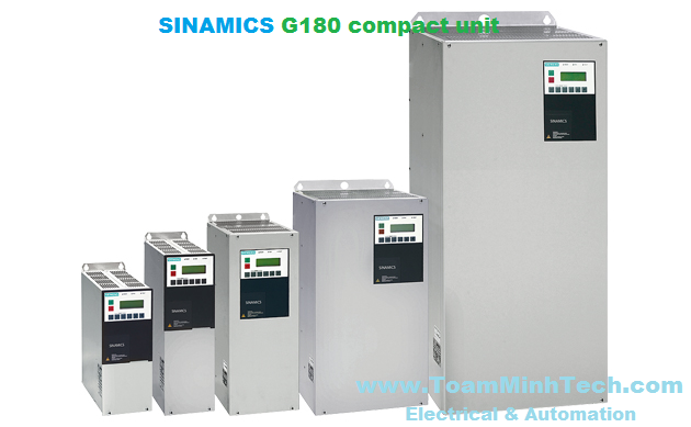

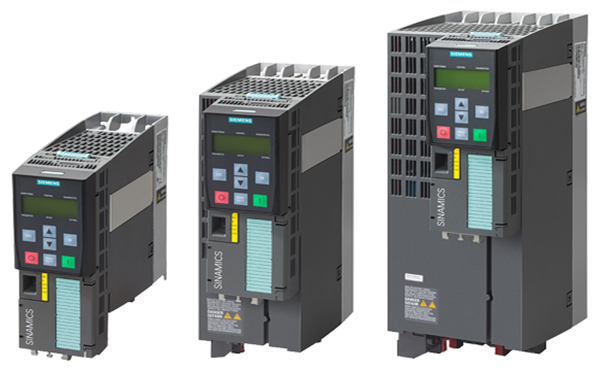
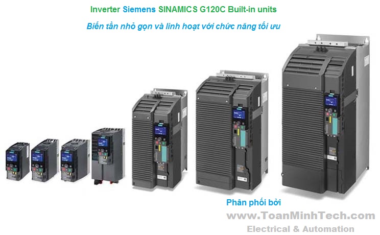
The compact version of the SINAMICS G180 is a converter that can be combined very flexibly with the associated system components and integrated into customer-specific control cabinets or directly into machines.
SINAMICS G180 converter compact units are manufactured in compliance with relevant international standards and regulations, and are therefore suitable for global use (see technical data).
SINAMICS G180 compact unit
SINAMICS G180 converter compact units are available for the following voltages and power ratings:
Overview of voltages and power ratings for SINAMICS G180 compact units
|
Rated line voltage |
Power |
|---|---|
|
400 V 3 AC |
2.2 ... 160 kW |
|
500 V 3 AC |
2.2 ... 200 kW |
|
690 V 3 AC |
7.5 ... 200 kW |
The most important directives and standards are listed below. These are used as basis for the SINAMICS G180 compact units and they must be carefully observed to achieve an EMC-compliant configuration that is safe both functionally and in operation.
|
European directives |
|
|---|---|
|
2006/95/EC |
Low-voltage directive: |
|
2004/108/EC |
EMC Directive: |
|
International and European standards |
|
|
EN 954-1 |
Safety of machinery – Safety-related parts of control systems; |
|
EN ISO 13849‑1 |
Safety of machinery – Safety-related parts of control systems; |
|
EN 60146‑1‑1 |
Semiconductor converters – General requirements and line-commutated converters |
|
EN 60204‑1 |
Electrical equipment of machines |
|
EN 60529 |
Degrees of protection provided by enclosures (IP code) |
|
EN 61140 |
Protection against electric shock - Common aspects for installation and equipment |
|
EN 61508‑1 |
Functional safety of electrical/electronic/programmable electronic safety-related systems, |
|
EN 61800‑2 |
Adjustable speed electrical power drive systems, |
|
EN 61800‑3 |
Adjustable speed electrical power drive systems, |
|
EN 61800-5-1 |
Adjustable speed electrical power drive systems, |
|
EN 61800‑5‑2 |
Adjustable speed electrical power drive systems, |
|
North American standards |
|
|
UL508C1) |
Power conversion equipment |
|
Approvals |
|
|
TÜV NRTL US1) |
Nationally Recognized Testing Laboratory |
1) On request
|
Electrical data |
|||
|---|---|---|---|
|
Line voltages |
Type of supply system |
Power ranges |
|
|
230 ... 400 ... 500 V 3 AC, -15/+10 % |
TN/TT system |
2.2 ... 160 kW (at 400 V) |
|
|
230 ... 500 V 3 AC, -15/+10 % |
IT system |
2.2 ... 200 kW (at 500 V) |
|
|
230 ... 690 V 3 AC, -15/+10 % |
TN/TT or IT system |
7.5 ... 200 kW (at 690 V) |
|
|
Line frequency |
47 ... 63 Hz |
||
|
Output frequency |
0 ... 250 Hz |
||
|
Voltage rise in motor |
Typ. 500 ... 1000 V/μs, but < 1500 V/μs |
||
|
Typical line harmonics (I) in % of fundamental mode for the 5/7/11/13/17/19/23/25 harmonics max. |
38/18/8/7/5/4/3/2 |
||
|
Typical line harmonics (I) in % of fundamental mode for the 5/7/11/13/17/19/23/25 harmonics max. with LHF filter |
1.4/3.6/2.4/1.7/1.0/0.6/0.8/0.4 |
||
|
Pulse number |
6 |
||
|
Overvoltage category |
III to EN 61800‑5‑1 |
||
|
Short Circuit Current Rating (SCCR) according to UL508C (up to 600 V), in conjunction with the specified fuses or circuit breakers |
60 kA |
||
|
Control method |
|
||
|
Fixed speeds |
3 fixed speeds + 1 minimum speed, parameterizable |
||
|
Skipped speed ranges |
2, parameterizable |
||
|
Setpoint resolution |
13 bits digital with n/f setpoint, 12 bits digital with U/I torque setpoint, 9 bits + sign analog |
||
|
Braking operation |
The oversaturation control system makes it possible to generate a braking torque of up to 50 % at low to mid-range speeds, and of up to 10 % at high speeds. If a higher braking torque is required, an optionally available braking module with appropriate braking resistor must be installed. |
||
|
Mechanical data |
|||
|
Degree of protection |
IP20, optionally IP21 provided by protective top cover (aluminum, unpainted) |
||
|
Protection class |
I acc. to EN 61800‑5‑1 |
||
|
Touch protection |
EN 50274 / BGV A3 |
||
|
Type of cooling |
Forced air cooling AF to EN 60146 |
||
|
Paint finish |
RAL 9023 (R-Pearl Dark Grey) |
||
|
Cable entry |
From below |
||
|
Ambient conditions2) |
Storage 3) |
Transport 3) |
Operation |
|
Ambient temperature |
-25 ... +70 °C |
-25 ... +70 °C |
Air: 0 ... 40 °C/ |
|
Relative humidity |
5 ... 95 % |
5 ... 95 % |
5 ... 95 % |
|
Environmental class/harmful |
Class 1C2 acc. to EN 60721‑3‑1 |
Class 2C2 acc. to EN 60721‑3‑2 |
Class 3C2 acc. to EN 60721‑3‑3 |
|
Organic/biological influences |
Class 1B1 acc. to EN 60721‑3‑1 |
Class 2B1 acc. to EN 60721‑3‑2 |
Class 3B1 acc. to EN 60721‑3‑3 |
|
Pollution degree |
2 acc. to EN 61800‑5‑1 |
||
|
Installation altitude |
Up to 1000 m above sea level without derating, > 1000 m see derating table (in chapter Configuring instructions) |
||
|
Mechanical stability2) |
Storage 3) |
Transport 3) |
Operation |
|
Vibratory load
|
1.5 mm at 5 ... 9 Hz 5 m/s2 at > 9 ... 200 Hz Class 1M2 acc. to EN 60721‑3‑1 |
3.1 mm at 5 ... 9 Hz 10 m/s2 at > 9 ... 200 Hz Class 2M2 acc. to EN 60721‑3‑2 |
0.075 mm at 10 … 58 Hz 10 m/s2 at > 58 … 200 Hz - |
|
Shock load
|
40 m/s2 at 22 ms Class 1M2 acc. to EN 60721‑3‑1 |
100 m/s2 at 11 ms Class 2M2 acc. to EN 60721‑3‑2 |
100 m/s2 at 11 ms Class 3M4 acc. to EN 60721‑3‑3 |
|
Compliance with standards |
|||
|
CE Label |
Acc. to EMC Directive No. 2004/108/EC and Low-Voltage Directive No. 2006/95/EC |
||
|
Radio interference suppression |
Complies with EMC guidelines defined in EN 61800‑3 thanks to line filter which is integrated as standard (with grounded supply system):
|
||
|
Approvals |
TÜV NRTL US2) |
||
1) On request
2) Higher standards on request
3) In transport packaging
Deviations from the specified classes are underlined.
|
Line voltage, supply system type |
|
230 ... 500 V 3 AC, TT/TN |
||||
|---|---|---|---|---|---|---|
|
SINAMICS G180 |
|
6SE0100‑1AC15‑5❑A7 |
6SE0100‑1AC17‑0❑A7 |
6SE0100‑1AC21‑0❑A7 |
6SE0100‑1AC21‑3❑A7 |
6SE0100‑1AC21‑8❑A7 |
|
Converter type |
|
2T2A‑07400‑002 |
2T2A‑07400‑003 |
2T2A‑07400‑004 |
2T2A‑07400‑005 |
2T2A‑07400‑007 |
|
Electrical data at motor end |
||||||
|
Type rating 1) |
|
|
|
|
|
|
|
kW |
2.2 |
3 |
4 |
5.5 |
7.5 |
|
hp |
3 |
5 |
6 |
9 |
12 |
|
Output voltage2) |
V |
0 ... 0.98 × Vline |
0 ... 0.98 × Vline |
0 ... 0.98 × Vline |
0 ... 0.98 × Vline |
0 ... 0.98 × Vline |
|
Output current |
|
|
|
|
|
|
|
A |
5.5 |
7 |
9.5 |
13 |
18 |
|
A |
6.5 |
8 |
11 |
15 |
20 |
|
Overload capability |
% |
18 |
14 |
16 |
15 |
11 |
|
Output power |
kVA |
3.8 |
4.8 |
6.6 |
9 |
12.5 |
|
Output frequency, max. |
Hz |
250 |
250 |
250 |
250 |
250 |
|
Rated clock cycle |
kHz |
4.5 |
4.5 |
4.5 |
4.5 |
4.5 |
|
adjustable from |
kHz |
3 ... 7.5 |
3 ... 7.5 |
3 ... 7.5 |
3 ... 7.5 |
3 ... 7.5 |
|
Power loss 3) |
kW |
0.13 |
0.16 |
0.2 |
0.26 |
0.33 |
|
Rated efficiency |
% |
95.2 |
95.8 |
95.9 |
96 |
96.2 |
|
Electrical data at line end |
||||||
|
Connected load |
kVA |
3.7 |
4.5 |
6.2 |
8.5 |
12 |
|
Rated input voltage |
V |
400 |
400 |
400 |
400 |
400 |
|
Input current |
|
|
|
|
|
|
|
A |
5.3 |
6.5 |
8.9 |
12.2 |
17.3 |
|
A |
6.3 |
7.4 |
10 |
14 |
19 |
|
Line fuse (provided by customer) |
gL (A) |
6 … 16 |
10 ... 16 |
10 ... 16 |
16 |
20 ... 32 |
|
λline |
|
0.927 |
0.94 |
0.918 |
0.937 |
0.918 |
|
Cos φline |
|
1 |
1 |
1 |
1 |
1 |
|
Radio interference suppression acc. to |
|
C2 (class A filter) |
C2 (class A filter) |
C2 (class A filter) |
C2 (class A filter) |
C2 (class A filter) |
|
Mechanical data |
||||||
|
Coolant requirements |
m3/h |
45 |
45 |
90 |
90 |
90 |
|
Sound pressure level LpA |
|
|
|
|
|
|
|
(1 m) at 50/60 Hz |
dB |
60 |
60 |
60 |
60 |
60 |
|
Max. cable length between converter and motor with standard insulation |
|
|
|
|
|
|
|
m |
200/3504) |
200/3504) |
200/3504) |
200/3504) |
200/3504) |
|
m |
150/3004) |
150/3004) |
150/3004) |
150/3004) |
150/3004) |
|
Line/load connection |
|
|
|
|
|
|
|
L1, L2, L3/U2, V2, W2 |
|
|
|
|
|
|
|
For connection cross-sections, see "Cable cross-sections and connections" in section "Configuring instructions" |
|
|
|
|
|
|
|
|
||||||
|
Dimensions |
|
|
|
|
|
|
|
mm |
165 |
165 |
165 |
165 |
165 |
|
mm |
410 |
410 |
410 |
410 |
510 |
|
mm |
320 |
320 |
320 |
320 |
320 |
|
Weight, approx. |
kg |
11.5 |
11.5 |
11.5 |
11.5 |
16.5 |
|
Approvals, according to |
|
NRTL5) |
NRTL5) |
NRTL5) |
NRTL5) |
NRTL5) |
|
Frame size |
|
K1 |
K1 |
K1 |
K1 |
K2 |
1) Rated power of a typical 2- to 6-pole standard motor.
2) Typical output voltage dependent on filter and unit type.
3) Maximum power loss with continuous current.
4) Value is applicable with option L10 (strengthened dv/dt filter; strengthened filter is integrated in unit).
5) On request
|
Line voltage, supply system type |
|
230 ... 500 V 3 AC, TT/TN |
||||
|---|---|---|---|---|---|---|
|
SINAMICS G180 |
|
6SE0100‑1AC22‑5❑A7 |
6SE0100‑1AC23‑7❑A7 |
6SE0100‑1AC24‑8❑A7 |
6SE0100‑1AC25‑8❑A7 |
6SE0100‑1AC27‑8❑A7 |
|
Converter type |
2T2A‑07400‑011 |
2T2A‑07400‑015 |
2T2A‑07400‑022 |
2T2A‑07400‑030 |
2T2A‑07400‑037 |
|
|
Electrical data at motor end |
||||||
|
Type rating 1) |
|
|
|
|
|
|
|
kW |
11 |
15 |
22 |
30 |
37 |
|
hp |
17 |
23 |
34 |
46 |
57 |
|
Output voltage2) |
V |
0 ... 0.98 × Vline |
0 ... 0.98 × Vline |
0 ... 0.98 × Vline |
0 ... 0.98 × Vline |
0 ... 0.98 × Vline |
|
Output current |
|
|
|
|
|
|
|
A |
24.5 |
37 |
48 |
58 |
78 |
|
A |
27 |
44 |
54 |
63 |
88 |
|
Overload capability |
% |
10 |
19 |
13 |
9 |
13 |
|
Output power |
kVA |
17 |
25.6 |
33.3 |
40.2 |
54 |
|
Output frequency, max. |
Hz |
250 |
250 |
250 |
250 |
250 |
|
Rated clock cycle |
kHz |
4.5 |
4.5 |
4.5 |
4.5 |
3 |
|
adjustable from |
kHz |
3 ... 7.5 |
3 ... 7.5 |
3 ... 7.5 |
3 ... 7.5 |
2 ... 5 |
|
Power loss 3) |
kW |
0.47 |
0.6 |
0.84 |
1.1 |
1.35 |
|
Rated efficiency |
% |
96.3 |
96.5 |
96.6 |
96.7 |
96.7 |
|
Electrical data at line end |
||||||
|
Connected load |
kVA |
15.7 |
24.3 |
31.8 |
39.1 |
52.2 |
|
Rated input voltage |
V |
400 |
400 |
400 |
400 |
400 |
|
Input current |
|
|
|
|
|
|
|
A |
22.7 |
35.1 |
45.9 |
56.5 |
75.3 |
|
A |
25 |
42 |
52 |
61 |
85 |
|
Line fuse (provided by customer) |
gL (A) |
25 ... 32 |
40 ... 80 |
50 ... 80 |
63 … 80 |
80 ... 100 |
|
λline |
|
0.932 |
0.932 |
0.932 |
0.924 |
0.932 |
|
Cos φline |
|
1 |
1 |
1 |
1 |
1 |
|
Radio interference suppression acc. to |
|
C2 (class A filter) |
C2 (class A filter) |
C2 (class A filter) |
C2 (class A filter) |
C2 (class A filter) |
|
Mechanical data |
||||||
|
Coolant requirements |
m3/h |
130 |
280 |
280 |
280 |
750 |
|
Sound pressure level LpA |
|
|
|
|
|
|
|
(1 m) at 50/60 Hz |
dB |
60 |
60 |
60 |
60 |
62 |
|
Max. cable length between converter and motor with standard insulation |
|
|
|
|
|
|
|
m |
200/3504) |
200/3504) |
200/3504) |
200/3504) |
200/3504) |
|
m |
150/3004) |
150/3004) |
150/3004) |
150/3004) |
150/3004) |
|
Line/load connection |
|
|||||
|
L1, L2, L3/U2, V2, W2 |
|
|||||
|
For connection cross-sections, see "Cable cross-sections and connections" in section "Configuring instructions" |
|
|||||
|
Dimensions |
|
|||||
|
mm |
165 |
225 |
225 |
225 |
350 |
|
mm |
510 |
610 |
610 |
610 |
710 |
|
mm |
320 |
320 |
320 |
320 |
320 |
|
Weight, approx. |
kg |
16.5 |
30 |
31 |
31 |
51 |
|
Approvals, according to |
|
NRTL5) |
NRTL5) |
NRTL5) |
NRTL5) |
NRTL5) |
|
Frame size |
|
K2 |
K3 |
K3 |
K3 |
K4 |
1) Rated power of a typical 2- to 6-pole standard motor.
2) Typical output voltage dependent on filter and unit type.
3) Maximum power loss with continuous current.
4) Value is applicable with option L10 (strengthened dv/dt filter; strengthened filter is integrated in unit).
5) On request
|
Line voltage, supply system type |
|
230 ... 500 V 3 AC, TT/TN |
||||
|---|---|---|---|---|---|---|
|
SINAMICS G180 |
|
6SE0100‑1AC28‑8❑A7 |
6SE0100‑1AC31‑1❑A7 |
6SE0100‑1AC31‑5❑A7 |
6SE0100‑1AC31‑8❑A7 |
6SE0100‑1AC32‑1❑A7 |
|
Converter type |
2T2A‑07400‑045 |
2T2A‑07400‑055 |
2T2A‑07400‑075 |
2T2A‑07400‑090 |
2T2A‑07400‑110 |
|
|
Electrical data at motor end |
||||||
|
Type rating 1) |
|
|
|
|
|
|
|
kW |
45 |
55 |
75 |
90 |
110 |
|
hp |
69 |
85 |
116 |
139 |
170 |
|
Output voltage2) |
V |
0 ... 0.98 × Vline |
0 ... 0.98 × Vline |
0 ... 0.98 × Vline |
0 ... 0.98 × Vline |
0 ... 0.98 × Vline |
|
Output current |
|
|
|
|
|
|
|
A |
88 |
110 |
145 |
175 |
205 |
|
A |
110 |
126 |
165 |
204 |
240 |
|
Overload capability |
% |
25 |
15 |
14 |
17 |
17 |
|
Output power |
kVA |
61 |
76.2 |
100 |
121 |
142 |
|
Output frequency, max. |
Hz |
250 |
250 |
250 |
250 |
250 |
|
Rated clock cycle |
kHz |
3 |
3 |
3 |
3 |
3 |
|
adjustable from |
kHz |
2 ... 5 |
2 ... 5 |
2 ... 5 |
2 ... 5 |
2 ... 5 |
|
Power loss 3) |
kW |
1.59 |
1.86 |
2.37 |
2.83 |
3.33 |
|
Rated efficiency |
% |
96.8 |
96.9 |
97.1 |
97.1 |
97.2 |
|
Electrical data at line end |
||||||
|
Connected load |
kVA |
57.3 |
74.8 |
97.7 |
119 |
134 |
|
Rated input voltage |
V |
400 |
400 |
400 |
400 |
400 |
|
Input current |
|
|
|
|
|
|
|
A |
82.7 |
108 |
141 |
172 |
194 |
|
A |
103 |
124 |
160 |
200 |
227 |
|
Line fuse (provided by customer) |
gL (A) |
100 |
125 |
160 |
200 |
200 ... 250 |
|
λline |
|
0.924 |
0.929 |
0.929 |
0.924 |
0.924 |
|
Cos φline |
|
1 |
1 |
1 |
1 |
1 |
|
Radio interference suppression acc. to |
|
C2 (class A filter) |
C2 (class A filter) |
C2 (class A filter) |
C2 (class A filter) |
C2 (class A filter) |
|
Mechanical data |
||||||
|
Coolant requirements |
m3/h |
750 |
750 |
1050 |
1050 |
1050 |
|
Sound pressure level LpA |
|
|
|
|
|
|
|
(1 m) at 50/60 Hz |
dB |
62 |
62 |
64 |
64 |
64 |
|
Max. cable length between converter and motor with standard insulation |
|
|
|
|
|
|
|
m |
200/3504) |
200/3504) |
200/3504) |
200/3504) |
200/3504) |
|
m |
150/3004) |
150/3004) |
150/3004) |
150/3004) |
150/3004) |
|
Line/load connection |
|
|
|
|
|
|
|
L1, L2, L3/U2, V2, W2 |
|
|
|
|
|
|
|
For connection cross-sections, see "Cable cross-sections and connections" in section "Configuring instructions" |
|
|
|
|
|
|
|
Dimensions |
|
|
|
|
|
|
|
mm |
350 |
350 |
350 |
350 |
350 |
|
mm |
710 |
710 |
1060 |
1060 |
1060 |
|
mm |
320 |
320 |
320 |
320 |
320 |
|
Weight, approx. |
kg |
53 |
55 |
90 |
94 |
96 |
|
Approvals, according to |
|
NRTL5) |
NRTL5) |
NRTL5) |
NRTL5) |
NRTL5) |
|
Frame size |
|
K4 |
K4 |
K5 |
K5 |
K5 |
1) Rated power of a typical 2- to 6-pole standard motor.
2) Typical output voltage dependent on filter and unit type.
3) Maximum power loss with continuous current.
4) Value is applicable with option L10 (strengthened dv/dt filter; strengthened filter is integrated in unit).
5) On request
|
Line voltage, supply system type |
|
230 ... 500 V 3 AC, TT/TN |
||||
|---|---|---|---|---|---|---|
|
SINAMICS G180 |
|
6SE0100‑1AC32‑5❑A7 |
6SE0100‑1AC33‑0❑A7 |
|
|
|
|
Converter type |
2T2A‑07400‑132 |
2T2A‑07400‑160 |
||||
|
Electrical data at motor end |
||||||
|
Type rating 1) |
|
|
|
|
|
|
|
kW |
132 |
160 |
|
|
|
|
hp |
204 |
247 |
|
|
|
|
Output voltage2) |
V |
0 ... 0.98 × Vline |
0 ... 0.98 × Vline |
|
|
|
|
Output current |
|
|
|
|
|
|
|
A |
245 |
295 |
|
|
|
|
A |
300 |
360 |
|
|
|
|
Overload capability |
% |
22 |
22 |
|
|
|
|
Output power |
kVA |
170 |
204 |
|
|
|
|
Output frequency, max. |
Hz |
250 |
250 |
|
|
|
|
Rated clock cycle |
kHz |
3 |
3 |
|
|
|
|
adjustable from |
kHz |
2 ... 5 |
2 ... 5 |
|
|
|
|
Power loss 3) |
kW |
3.84 |
4.65 |
|
|
|
|
Rated efficiency |
% |
97.3 |
97.3 |
|
|
|
|
Electrical data at line end |
||||||
|
Connected load |
kVA |
161 |
197 |
|
|
|
|
Rated input voltage |
V |
400 |
400 |
|
|
|
|
Input current |
|
|
|
|
|
|
|
A |
232 |
284 |
|
|
|
|
A |
284 |
347 |
|
|
|
|
Line fuse (provided by customer) |
gL (A) |
250 ... 315 |
315 ... 400 |
|
|
|
|
λline |
|
0.924 |
0.924 |
|
|
|
|
Cos φline |
|
1 |
1 |
|
|
|
|
Radio interference suppression acc. to |
|
C2 (class A filter) |
C2 (class A filter) |
|
|
|
|
Mechanical data |
||||||
|
Coolant requirements |
m3/h |
1600 |
1600 |
|
|
|
|
Sound pressure level LpA |
|
|
|
|
|
|
|
(1 m) at 50/60 Hz |
dB |
66 |
66 |
|
|
|
|
Max. cable length between converter and motor with standard insulation |
|
|
|
|
|
|
|
m |
200/3504) |
200/3504) |
|
|
|
|
m |
150/3004) |
150/3004) |
|
|
|
|
Line/load connection |
|
|
|
|
|
|
|
L1, L2, L3/U2, V2, W2 |
|
|
|
|
|
|
|
For connection cross-sections, see "Cable cross-sections and connections" in section "Configuring instructions" |
|
|
|
|
|
|
|
Dimensions |
|
|
|
|
|
|
|
mm |
500 |
500 |
|
|
|
|
mm |
1060 |
1060 |
|
|
|
|
mm |
320 |
320 |
|
|
|
|
Weight, approx. |
kg |
160 |
170 |
|
|
|
|
Approvals, according to |
|
NRTL5) |
NRTL5) |
|
|
|
|
Frame size |
|
K6 |
K6 |
|
|
|
1) Rated power of a typical 2- to 6-pole standard motor.
2) Typical output voltage dependent on filter and unit type.
3) Maximum power loss with continuous current.
4) Value is applicable with option L10 (strengthened dv/dt filter; strengthened filter is integrated in unit).
5) On request
|
Line voltage, supply system type |
|
230 ... 500 V 3 AC, IT |
||||
|---|---|---|---|---|---|---|
|
SINAMICS G180 |
|
6SE0100‑1AD14‑5❑A7 |
6SE0100‑1AD15‑5❑A7 |
6SE0100‑1AD17‑0❑A7 |
6SE0100‑1AD21‑0❑A7 |
6SE0100‑1AD21‑3❑A7 |
|
Converter type |
2T2A‑07500‑002 |
2T2A‑07500‑003 |
2T2A‑07500‑004 |
2T2A‑07500‑005 |
2T2A‑07500‑007 |
|
|
Electrical data at motor end |
||||||
|
Type rating 1) |
|
|
|
|
|
|
|
kW |
2.2 |
3 |
4 |
5.5 |
7.5 |
|
hp |
3 |
4 |
5 |
7 |
9 |
|
Output voltage2) |
V |
0 ... 0.98 × Vline |
0 ... 0.98 × Vline |
0 ... 0.98 × Vline |
0 ... 0.98 × Vline |
0 ... 0.98 × Vline |
|
Output current |
|
|
|
|
|
|
|
A |
4.5 |
5.5 |
7 |
9.5 |
13 |
|
A |
5 |
6.5 |
8 |
11 |
15 |
|
Overload capability |
% |
11 |
18 |
14 |
16 |
15 |
|
Output power |
kVA |
3.9 |
4.8 |
6.1 |
8.2 |
11.3 |
|
Output frequency, max. |
Hz |
250 |
250 |
250 |
250 |
250 |
|
Rated clock cycle |
kHz |
4.5 |
4.5 |
4.5 |
4.5 |
4.5 |
|
adjustable from |
kHz |
3 ... 7.5 |
3 ... 7.5 |
3 ... 7.5 |
3 ... 7.5 |
3 ... 7.5 |
|
Power loss 3) |
kW |
0.12 |
0.16 |
0.2 |
0.26 |
0.34 |
|
Rated efficiency |
% |
95.6 |
95.7 |
95.9 |
96.0 |
96.1 |
|
Electrical data at line end |
||||||
|
Connected load |
kVA |
3.7 |
4.6 |
6.4 |
8.6 |
12.1 |
|
Rated input voltage |
V |
500 |
500 |
500 |
500 |
500 |
|
Input current |
|
|
|
|
|
|
|
A |
4.4 |
5.2 |
6.5 |
9.3 |
12.5 |
|
A |
4.9 |
6.1 |
7.4 |
11 |
14 |
|
Line fuse (provided by customer) |
gL (A) |
4 ... 16 |
6 ... 16 |
10 ... 16 |
10 ... 16 |
16 |
|
λline |
|
0.902 |
0.912 |
0.932 |
0.908 |
0.927 |
|
Cos φline |
|
1 |
1 |
1 |
1 |
1 |
|
Radio interference suppression acc. to |
|
C4 |
C4 |
C4 |
C4 |
C4 |
|
Mechanical data |
||||||
|
Coolant requirements |
m3/h |
45 |
45 |
45 |
90 |
90 |
|
Sound pressure level LpA |
|
|
|
|
|
|
|
(1 m) at 50/60 Hz |
dB |
60 |
60 |
60 |
60 |
60 |
|
Max. cable length between converter and motor with standard insulation |
|
|
|
|
|
|
|
m |
3004) |
3004) |
3004) |
3004) |
3004) |
|
Line/load connection |
|
|
|
|
|
|
|
L1, L2, L3/U2, V2, W2 |
|
|
|
|
|
|
|
For connection cross-sections, see "Cable cross-sections and connections" in section "Configuring instructions" |
|
|
|
|
|
|
|
Dimensions |
|
|
|
|
|
|
|
mm |
165 |
165 |
165 |
165 |
165 |
|
mm |
410 |
410 |
410 |
410 |
410 |
|
mm |
320 |
320 |
320 |
320 |
320 |
|
Weight, approx. |
kg |
11.5 |
11.5 |
11.5 |
11.5 |
11.5 |
|
Approvals, according to |
|
NRTL5) |
NRTL5) |
NRTL5) |
NRTL5) |
NRTL5) |
|
Frame size |
|
K1 |
K1 |
K1 |
K1 |
K1 |
1) Rated power of a typical 2- to 6-pole standard motor.
2) Typical output voltage dependent on filter and unit type.
3) Maximum power loss with continuous current.
4) Option L10 included (strengthened dv/dt filter; strengthened filter is integrated in unit).
5) On request
|
Line voltage, supply system type |
|
230 ... 500 V 3 AC, IT |
||||
|---|---|---|---|---|---|---|
|
SINAMICS G180 |
|
6SE0100‑1AD21‑8❑A7 |
6SE0100‑1AD22‑5❑A7 |
6SE0100‑1AD23‑7❑A7 |
6SE0100‑1AD24‑8❑A7 |
6SE0100‑1AD25‑8❑A7 |
|
Converter type |
2T2A‑07500‑011 |
2T2A‑07500‑015 |
2T2A‑07500‑022 |
2T2A‑07500‑030 |
2T2A‑07500‑037 |
|
|
Electrical data at motor end |
||||||
|
Type rating 1) |
|
|
|
|
|
|
|
kW |
11 |
15 |
22 |
30 |
37 |
|
hp |
17 |
23 |
34 |
46 |
57 |
|
Output voltage2) |
V |
0 ... 0.98 × Vline |
0 ... 0.98 × Vline |
0 ... 0.98 × Vline |
0 ... 0.98 × Vline |
0 ... 0.98 × Vline |
|
Output current |
|
|
|
|
|
|
|
A |
18 |
24.5 |
37 |
48 |
58 |
|
A |
20 |
27 |
44 |
54 |
63 |
|
Overload capability |
% |
11 |
10 |
19 |
13 |
9 |
|
Output power |
kVA |
15.6 |
21.2 |
32 |
41.6 |
50.2 |
|
Output frequency, max. |
Hz |
250 |
250 |
250 |
250 |
250 |
|
Rated clock cycle |
kHz |
4.5 |
4.5 |
4.5 |
4.5 |
4.5 |
|
adjustable from |
kHz |
3 ... 7.5 |
3 ... 7.5 |
3 ... 7.5 |
3 ... 7.5 |
3 ... 7.5 |
|
Power loss 3) |
kW |
0.48 |
0.63 |
0.89 |
1.17 |
1.35 |
|
Rated efficiency |
% |
96.2 |
96.3 |
96.4 |
96.5 |
96.7 |
|
Electrical data at line end |
||||||
|
Connected load |
kVA |
16 |
24.4 |
32 |
39.2 |
52.3 |
|
Rated input voltage |
V |
500 |
500 |
500 |
500 |
500 |
|
Input current |
|
|
|
|
|
|
|
A |
17.4 |
23.4 |
35.8 |
46.8 |
57.1 |
|
A |
19 |
26 |
43 |
53 |
62 |
|
Line fuse (provided by customer) |
gL (A) |
20 ... 32 |
25 ... 32 |
40 ... 80 |
50 ... 80 |
63 ... 80 |
|
λline |
|
0.902 |
0.924 |
0.918 |
0.924 |
0.912 |
|
Cos φline |
|
1 |
1 |
1 |
1 |
1 |
|
Radio interference suppression acc. to |
|
C4 |
C4 |
C4 |
C4 |
C4 |
|
Mechanical data |
||||||
|
Coolant requirements |
m3/h |
90 |
130 |
280 |
280 |
280 |
|
Sound pressure level LpA |
|
|
|
|
|
|
|
(1 m) at 50/60 Hz |
dB |
60 |
60 |
60 |
60 |
62 |
|
Max. cable length between converter and motor with standard insulation |
|
|
|
|
|
|
|
m |
3004) |
3004) |
3004) |
3004) |
3004) |
|
Line/load connection |
|
|
|
|
|
|
|
L1, L2, L3/U2, V2, W2 |
|
|
|
|
|
|
|
For connection cross-sections, see "Cable cross-sections and connections" in section "Configuring instructions" |
|
|
|
|
|
|
|
Dimensions |
|
|
|
|
|
|
|
mm |
165 |
165 |
225 |
225 |
225 |
|
mm |
510 |
510 |
610 |
610 |
610 |
|
mm |
320 |
320 |
320 |
320 |
320 |
|
Weight, approx. |
kg |
16.5 |
17.5 |
30 |
32 |
32 |
|
Approvals, according to |
|
NRTL5) |
NRTL5) |
NRTL5) |
NRTL5) |
NRTL5) |
|
Frame size |
|
K2 |
K2 |
K3 |
K3 |
K3 |
1) Rated power of a typical 2- to 6-pole standard motor.
2) Typical output voltage dependent on filter and unit type.
3) Maximum power loss with continuous current.
4) Option L10 included (strengthened dv/dt filter; strengthened filter is integrated in unit).
5) On request
|
Line voltage, supply system type |
|
230 ... 500 V 3 AC, IT |
||||
|---|---|---|---|---|---|---|
|
SINAMICS G180 |
|
6SE0100‑ |
6SE0100‑ |
6SE0100‑ |
6SE0100‑ |
6SE0100‑ |
|
Converter type |
2T2A‑ |
2T2A‑ |
2T2A‑ |
2T2A‑ |
2T2A‑ |
|
|
Electrical data at motor end |
||||||
|
Type rating 1) |
|
|
|
|
|
|
|
kW |
45 |
55 |
75 |
90 |
110 |
|
hp |
56 |
68 |
93 |
111 |
136 |
|
Output voltage2) |
V |
0 ... 0.98 × Vline |
0 ... 0.98 × Vline |
0 ... 0.98 × Vline |
0 ... 0.98 × Vline |
0 ... 0.98 × Vline |
|
Output current |
|
|
|
|
|
|
|
A |
78 |
88 |
110 |
145 |
175 |
|
A |
88 |
110 |
126 |
165 |
204 |
|
Overload capability |
% |
13 |
25 |
15 |
14 |
17 |
|
Output power |
kVA |
67.5 |
76.2 |
95.3 |
126 |
152 |
|
Output frequency, max. |
Hz |
250 |
250 |
250 |
250 |
250 |
|
Rated clock cycle |
kHz |
3 |
3 |
3 |
3 |
3 |
|
adjustable from |
kHz |
2 ... 5 |
2 ... 5 |
2 ... 5 |
20 ... 5 |
2 ... 5 |
|
Power loss 3) |
kW |
1.59 |
1.8 |
2.37 |
2.83 |
3.33 |
|
Rated efficiency |
% |
96.8 |
97.0 |
97.1 |
97.1 |
97.2 |
|
Electrical data at line end |
||||||
|
Connected load |
kVA |
57.5 |
74.8 |
98.4 |
119 |
136 |
|
Rated input voltage |
V |
500 |
500 |
500 |
500 |
500 |
|
Input current |
|
|
|
|
|
|
|
A |
73.7 |
87.6 |
109 |
143 |
170 |
|
A |
83 |
110 |
125 |
163 |
198 |
|
Line fuse (provided by customer) |
gL (A) |
80 ... 100 |
100 |
125 |
160 |
200 |
|
λline |
|
0.918 |
0.912 |
0.918 |
0.918 |
0.908 |
|
Cos φline |
|
1 |
1 |
1 |
1 |
1 |
|
Radio interference suppression acc. to |
|
C4 |
C4 |
C4 |
C4 |
C4 |
|
Mechanical data |
||||||
|
Coolant requirements |
m3/h |
750 |
750 |
750 |
1050 |
1050 |
|
Sound pressure level LpA |
|
|
|
|
|
|
|
(1 m) at 50/60 Hz |
dB |
62 |
62 |
64 |
64 |
64 |
|
Max. cable length between converter and motor with standard insulation |
|
|
|
|
|
|
|
m |
3004) |
3004) |
3004) |
3004) |
3004) |
|
Line/load connection |
|
|
|
|
|
|
|
L1, L2, L3/U2, V2, W2 |
|
|
|
|
|
|
|
For connection cross-sections, see "Cable cross-sections and connections" in section "Configuring instructions" |
|
|
|
|
|
|
|
Dimensions |
|
|
|
|
|
|
|
mm |
350 |
350 |
350 |
350 |
350 |
|
mm |
710 |
710 |
710 |
1060 |
1060 |
|
mm |
320 |
320 |
320 |
320 |
320 |
|
Weight, approx. |
kg |
51 |
53 |
55 |
90 |
94 |
|
Approvals, according to |
|
NRTL5) |
NRTL5) |
NRTL5) |
NRTL5) |
NRTL5) |
|
Frame size |
|
K4 |
K4 |
K4 |
K5 |
K5 |
1) Rated power of a typical 2- to 6-pole standard motor.
2) Typical output voltage dependent on filter and unit type.
3) Maximum power loss with continuous current.
4) Option L10 included (strengthened dv/dt filter; strengthened filter is integrated in unit).
5) On request
|
Line voltage, supply system type |
|
230 ... 500 V 3 AC, IT |
||||
|---|---|---|---|---|---|---|
|
SINAMICS G180 |
|
6SE0100‑ |
6SE0100‑ |
6SE0100‑ |
|
|
|
Converter type |
2T2A‑ |
2T2A‑ |
2T2A‑ |
|||
|
Electrical data at motor end |
||||||
|
Type rating 1) |
|
|
|
|
|
|
|
kW |
132 |
160 |
200 |
|
|
|
hp |
163 |
197 |
247 |
|
|
|
Output voltage2) |
V |
0 ... 0.98 × Vline |
0 ... 0.98 × Vline |
0 ... 0.98 × Vline |
|
|
|
Output current |
|
|
|
|
|
|
|
A |
205 |
245 |
295 |
|
|
|
A |
240 |
300 |
360 |
|
|
|
Overload capability |
% |
17 |
22 |
22 |
|
|
|
Output power |
kVA |
178 |
212 |
256 |
|
|
|
Output frequency, max. |
Hz |
250 |
250 |
250 |
|
|
|
Rated clock cycle |
kHz |
3 |
3 |
3 |
|
|
|
adjustable from |
kHz |
2 ... 5 |
2 ... 5 |
2 ... 5 |
|
|
|
Power loss 3) |
kW |
3.84 |
4.48 |
5.6 |
|
|
|
Rated efficiency |
% |
97.3 |
97.4 |
97.4 |
|
|
|
Electrical data at line end |
||||||
|
Connected load |
kVA |
161 |
197 |
3.8 |
|
|
|
Rated input voltage |
V |
500 |
500 |
500 |
|
|
|
Input current |
|
|
|
|
|
|
|
A |
196 |
237 |
286 |
|
|
|
A |
230 |
290 |
349 |
|
|
|
Line fuse (provided by customer) |
gL (A) |
200 ... 250 |
250 ... 315 |
315 ... 400 |
|
|
|
λline |
|
0.912 |
0.912 |
0.912 |
|
|
|
Cos φline |
|
1 |
1 |
1 |
|
|
|
Radio interference suppression acc. to |
|
C4 |
C4 |
C4 |
|
|
|
Mechanical data |
||||||
|
Coolant requirements |
m3/h |
1050 |
1600 |
1600 |
|
|
|
Sound pressure level LpA |
|
|
|
|
|
|
|
(1 m) at 50/60 Hz |
dB |
66 |
66 |
60 |
|
|
|
Max. cable length between converter and motor with standard insulation |
|
|
|
|
|
|
|
m |
3004) |
3004) |
3004) |
|
|
|
Line/load connection |
|
|
|
|
|
|
|
L1, L2, L3/U2, V2, W2 |
|
|
|
|
|
|
|
For connection cross-sections, see "Cable cross-sections and connections" in section "Configuring instructions" |
|
|
|
|
|
|
|
Dimensions |
|
|
|
|
|
|
|
mm |
350 |
500 |
500 |
|
|
|
mm |
1060 |
1060 |
1060 |
|
|
|
mm |
320 |
320 |
320 |
|
|
|
Weight, approx. |
kg |
96 |
170 |
180 |
|
|
|
Approvals, according to |
|
NRTL5) |
NRTL5) |
NRTL5) |
|
|
|
Frame size |
|
K5 |
K6 |
K6 |
|
|
1) Rated power of a typical 2- to 6-pole standard motor.
2) Typical output voltage dependent on filter and unit type.
3) Maximum power loss with continuous current.
4) Option L10 included (strengthened dv/dt filter; strengthened filter is integrated in unit).
5) On request
|
Line voltage, supply system type |
|
230 ... 690 V 3 AC, TT/TN or IT |
||||
|---|---|---|---|---|---|---|
|
SINAMICS G180 |
|
6SE0100‑ |
6SE0100‑ |
6SE0100‑ |
6SE0100‑ |
6SE0100‑ |
|
Converter type |
2T2A‑ |
2T2A‑ |
2T2A‑ |
2T2A‑ |
2T2A‑ |
|
|
Electrical data at motor end |
||||||
|
Type rating 1) |
|
|
|
|
|
|
|
kW |
7.5 |
11 |
15 |
22 |
30 |
|
hp |
8 |
12 |
17 |
25 |
34 |
|
Output voltage2) |
V |
0 ... 0.98 × Vline |
0 ... 0.98 × Vline |
0 ... 0.98 × Vline |
0 ... 0.98 × Vline |
0 ... 0.98 × Vline |
|
Output current |
|
|
|
|
|
|
|
A |
9.5 |
13 |
18 |
27 |
36 |
|
A |
11 |
16 |
21 |
33 |
45 |
|
Overload capability |
% |
16 |
23 |
17 |
22 |
25 |
|
Output power |
kVA |
11.4 |
15.5 |
21.5 |
32.3 |
43 |
|
Output frequency, max. |
Hz |
250 |
250 |
250 |
250 |
250 |
|
Rated clock cycle |
kHz |
3 |
3 |
3 |
3 |
3 |
|
adjustable from |
kHz |
2 ... 5 |
2 ... 5 |
2 ... 5 |
2 ... 5 |
2 ... 5 |
|
Power loss 3) |
kW |
0.29 |
0.4 |
0.55 |
0.74 |
1 |
|
Rated efficiency |
% |
96.7 |
96.8 |
96.8 |
97.0 |
97.0 |
|
Electrical data at line end |
||||||
|
Connected load |
kVA |
3.7 |
4.6 |
6.4 |
8.6 |
12.1 |
|
Rated input voltage |
V |
690 |
690 |
690 |
690 |
690 |
|
Input current |
|
|
|
|
|
|
|
A |
8.8 |
11.8 |
16.8 |
25.3 |
37.3 |
|
A |
10 |
14 |
20 |
31 |
47 |
|
Line fuse (provided by customer) |
gL (A) |
10 ... 32 |
16 ... 32 |
20 ... 32 |
32 |
40 ... 63 |
|
λline |
|
0.94 |
0.948 |
0.94 |
0.948 |
0.867 |
|
Cos φline |
|
1 |
1 |
1 |
1 |
1 |
|
Radio interference suppression acc. to |
|
C2 (class A filter) |
C2 (class A filter) |
C2 (class A filter) |
C2 (class A filter) |
C2 (class A filter) |
|
Mechanical data |
||||||
|
Coolant requirements |
m3/h |
90 |
90 |
130 |
130 |
750 |
|
Sound pressure level LpA |
|
|
|
|
|
|
|
(1 m) at 50/60 Hz |
dB |
60 |
60 |
60 |
60 |
60 |
|
Max. cable length between converter and motor with standard insulation |
|
|
|
|
|
|
|
m |
3005) |
3005) |
3005) |
3005) |
3005) |
|
Line/load connection |
|
|
|
|
|
|
|
L1, L2, L3/U2, V2, W2 |
|
|
|
|
|
|
|
For connection cross-sections, see "Cable cross-sections and connections" in section "Configuring instructions" |
|
|
|
|
|
|
|
Dimensions |
|
|
|
|
|
|
|
mm |
225 |
225 |
225 |
225 |
350 |
|
mm |
610 |
610 |
610 |
610 |
710 |
|
mm |
320 |
320 |
320 |
320 |
320 |
|
Weight, approx. |
kg |
26 |
26 |
28 |
28 |
55 |
|
Approvals, according to |
|
NRTL6) |
NRTL6) |
NRTL6) |
NRTL6) |
NRTL6) |
|
Frame size |
|
K3 |
K3 |
K3 |
K3 |
K4 |
1) Rated power of a typical 2- to 6-pole standard motor.
2) Typical output voltage dependent on filter and unit type.
3) Maximum power loss with continuous current.
4) EMC filter not required for IT system, in which case RI suppression category C4.
5) Value is applicable with option L10 (strengthened dv/dt filter; strengthened filter is integrated in unit).
6) On request; the voltage range for NRTL units ends at max. 600 V.
|
Line voltage, supply system type |
|
230 ... 690 V 3 AC, TT/TN or IT |
||||
|---|---|---|---|---|---|---|
|
SINAMICS G180 |
|
6SE0100‑ |
6SE0100‑ |
6SE0100‑ |
6SE0100‑ |
6SE0100‑ |
|
Converter type |
2T2A‑ |
2T2A‑ |
2T2A‑ |
2T2A‑ |
2T2A‑ |
|
|
Electrical data at motor end |
||||||
|
Type rating 1) |
|
|
|
|
|
|
|
kW |
37 |
45 |
55 |
75 |
90 |
|
hp |
41 |
50 |
62 |
84 |
101 |
|
Output voltage2) |
V |
0 ... 0.98 × Vline |
0 ... 0.98 × Vline |
0 ... 0.98 × Vline |
0 ... 0.98 × Vline |
0 ... 0.98 × Vline |
|
Output current |
|
|
|
|
|
|
|
A |
43 |
50 |
60 |
80 |
95 |
|
A |
55 |
65 |
75 |
90 |
120 |
|
Overload capability |
% |
28 |
30 |
25 |
13 |
26 |
|
Output power |
kVA |
51.4 |
59.8 |
71.7 |
95.6 |
114 |
|
Output frequency, max. |
Hz |
250 |
250 |
250 |
250 |
250 |
|
Rated clock cycle |
kHz |
3 |
3 |
3 |
3 |
3 |
|
adjustable from |
kHz |
2 ... 5 |
2 ... 5 |
2 ... 5 |
2 ... 5 |
2 ... 5 |
|
Power loss 3) |
kW |
1.19 |
1.44 |
1.68 |
2.28 |
2.63 |
|
Rated efficiency |
% |
97.1 |
97.1 |
97.2 |
97.2 |
97.3 |
|
Electrical data at line end |
||||||
|
Connected load |
kVA |
16 |
24.4 |
32 |
39.2 |
52.3 |
|
Rated input voltage |
V |
690 |
690 |
690 |
690 |
690 |
|
Input current |
|
|
|
|
|
|
|
A |
42.9 |
50.1 |
60.7 |
80.9 |
102 |
|
A |
55 |
65 |
76 |
91 |
129 |
|
Line fuse (provided by customer) |
gL (A) |
50 ... 63 |
63 |
63 ... 80 |
100 |
125 |
|
λline |
|
0.898 |
0.863 |
0.894 |
0.896 |
0.845 |
|
Cos φline |
|
1 |
1 |
1 |
1 |
1 |
|
Radio interference suppression acc. to |
|
C2 (class A filter) |
C2 (class A filter) |
C2 (class A filter) |
C2 (class A filter) |
C2 (class A filter) |
|
Mechanical data |
||||||
|
Coolant requirements |
m3/h |
750 |
750 |
750 |
750 |
1050 |
|
Sound pressure level LpA |
|
|
|
|
|
|
|
(1 m) at 50/60 Hz |
dB |
60 |
60 |
60 |
60 |
62 |
|
Max. cable length between converter and motor with standard insulation |
|
|
|
|
|
|
|
m |
3005) |
3005) |
3005) |
3005) |
150 (300) 6) |
|
Line/load connection |
|
|
|
|
|
|
|
L1, L2, L3/U2, V2, W2 |
|
|
|
|
|
|
|
For connection cross-sections, see "Cable cross-sections and connections" in section "Configuring instructions" |
|
|
|
|
|
|
|
Dimensions |
|
|
|
|
|
|
|
mm |
350 |
350 |
350 |
350 |
350 |
|
mm |
710 |
710 |
710 |
710 |
1060 |
|
mm |
320 |
320 |
320 |
320 |
320 |
|
Weight, approx. |
kg |
55 |
59 |
59 |
59 |
90 |
|
Approvals, according to |
|
NRTL7) |
NRTL7) |
NRTL7) |
NRTL7) |
NRTL7) |
|
Frame size |
|
K4 |
K4 |
K4 |
K4 |
K5 |
1) Rated power of a typical 2- to 6-pole standard motor.
2) Typical output voltage dependent on filter and unit type.
3) Maximum power loss with continuous current.
4) EMC filter not required for IT system, in which case RI suppression category C4.
5) Value is applicable with option L10 (strengthened dv/dt filter; strengthened filter is integrated in unit).
6) Value is applicable with option L10 (strengthened dv/dt filter; strengthened filter is supplied separately with unit).
7) On request; the voltage range for NRTL units ends at max. 600 V.
|
Line voltage, supply system type |
|
230 ... 690 V 3 AC, TT/TN or IT |
||||
|---|---|---|---|---|---|---|
|
SINAMICS G180 |
|
6SE0100‑ |
6SE0100‑ |
6SE0100‑ |
6SE0100‑ |
|
|
Converter type |
2T2A‑ |
2T2A‑ |
2T2A‑ |
2T2A‑ |
||
|
Electrical data at motor end |
||||||
|
Type rating 1) |
|
|
|
|
|
|
|
kW |
110 |
132 |
160 |
200 |
|
|
hp |
122 |
148 |
179 |
224 |
|
|
Output voltage2) |
V |
0 ... 0.98 × Vline |
0 ... 0.98 × Vline |
0 ... 0.98 × Vline |
0 ... 0.98 × Vline |
|
|
Output current |
|
|
|
|
|
|
|
A |
120 |
150 |
175 |
210 |
|
|
A |
140 |
175 |
210 |
255 |
|
|
Overload capability |
% |
17 |
17 |
20 |
21 |
|
|
Output power |
kVA |
143 |
179 |
209 |
251 |
|
|
Output frequency, max. |
Hz |
250 |
250 |
250 |
250 |
|
|
Rated clock cycle |
kHz |
3 |
3 |
3 |
3 |
|
|
adjustable from |
kHz |
2 ... 5 |
2 ... 5 |
2 ... 5 |
2 ... 5 |
|
|
Power loss 3) |
kW |
3.21 |
3.7 |
4.48 |
5.38 |
|
|
Rated efficiency |
% |
97.3 |
97.4 |
97.4 |
97.5 |
|
|
Electrical data at line end |
||||||
|
Connected load |
kVA |
57.5 |
74.8 |
98.4 |
119 |
|
|
Rated input voltage |
V |
690 |
690 |
690 |
690 |
|
|
Input current |
|
|
|
|
|
|
|
A |
119 |
153 |
180 |
222 |
|
|
A |
139 |
178 |
216 |
270 |
|
|
Line fuse (provided by customer) |
gL (A) |
125 ... 160 |
160 ... 200 |
200 ... 250 |
250 ... 315 |
|
|
λline |
|
0.883 |
0.857 |
0.862 |
0.838 |
|
|
Cos φline |
|
1 |
1 |
1 |
1 |
|
|
Radio interference suppression acc. to |
|
C2 (class A filter) |
C2 (class A filter) |
C2 (class A filter) |
C2 (class A filter) |
|
|
Mechanical data |
||||||
|
Coolant requirements |
m3/h |
1050 |
1050 |
1600 |
1600 |
|
|
Sound pressure level LpA |
|
|
|
|
|
|
|
(1 m) at 50/60 Hz |
dB |
62 |
62 |
64 |
64 |
|
|
Max. cable length between converter and motor with standard insulation |
|
|
|
|
|
|
|
m |
150/3004) |
150/3004) |
150/3004) |
150/3004) |
|
|
Line/load connection |
|
|
|
|
|
|
|
L1, L2, L3/U2, V2, W2 |
|
|
|
|
|
|
|
For connection cross-sections, see "Cable cross-sections and connections" in section "Configuring instructions" |
|
|
|
|
|
|
|
Dimensions |
|
|
|
|
|
|
|
mm |
350 |
350 |
500 |
500 |
|
|
mm |
1060 |
1060 |
1060 |
1060 |
|
|
mm |
320 |
320 |
320 |
320 |
|
|
Weight, approx. |
kg |
94 |
96 |
170 |
180 |
|
|
Approvals, according to |
|
NRTL5) |
NRTL5) |
NRTL5) |
NRTL5) |
|
|
Frame size |
|
K5 |
K5 |
K6 |
K6 |
|
1) Rated power of a typical 2- to 6-pole standard motor.
2) Typical output voltage dependent on filter and unit type.
3) Maximum power loss with continuous current.
4) Value is applicable with option L10 (strengthened dv/dt filter; strengthened filter is supplied separately with unit).
5) On request; the voltage range for NRTL units ends at max. 600 V.
The following tables provide an overview of the options and their availability for SINAMICS G180 compact units with a supply voltage of 400 V, 500 V or 690 V. (For details, see catalog chapter 4 "Option descriptions".)
|
|
|
SINAMICS G180 compact units |
|||||||||||||||
|---|---|---|---|---|---|---|---|---|---|---|---|---|---|---|---|---|---|
|
|
|
400 V TN/TT system |
500 V IT system |
690 V TN/TT system |
690 V IT system |
||||||||||||
|
|
|
Version – see selection and ordering data |
|||||||||||||||
|
Option text |
Additional ordering data -Z with order code and, if necessary, with plain text specification |
A |
B |
C |
D |
E |
F |
G |
H |
I |
J |
K |
L |
M |
N |
O |
P |
|
External control voltage supply |
|||||||||||||||||
|
Connection for 230 V 1 AC 50 Hz control voltage provided by customer, without UPS backup |
C56 |
✓ |
✓ |
✓ |
✓ |
✓ |
✓ |
✓ |
✓ |
✓ |
✓ |
✓ |
✓ |
✓ |
✓ |
✓ |
✓ |
|
Connection for 230 V 1 AC 50 Hz control voltage provided by customer, with UPS backup |
C57 |
✓ |
✓ |
✓ |
✓ |
✓ |
✓ |
✓ |
✓ |
✓ |
✓ |
✓ |
✓ |
✓ |
✓ |
✓ |
✓ |
|
RFI suppression filter |
|||||||||||||||||
|
RFI suppression filter, category C2 or C3 (class A) |
L00 |
❑ |
❑ |
❑ |
❑ |
– |
– |
– |
– |
❑ |
❑ |
❑ |
❑ |
– |
– |
– |
– |
|
RFI suppression filter, category C1 (class B) |
L02 |
✓ |
✓ |
✓ |
✓ |
– |
– |
– |
– |
– |
– |
– |
– |
– |
– |
– |
– |
|
Line Harmonics Filter |
|||||||||||||||||
|
Line Harmonics Filter for 50 Hz line frequency (supplied separately packed) |
L03 |
✓ |
✓ |
✓ |
✓ |
✓ |
✓ |
✓ |
✓ |
✓ |
✓ |
✓ |
✓ |
✓ |
✓ |
✓ |
✓ |
|
Line Harmonics Filter for 60 Hz line frequency up to 480 V (supplied separately packed) |
L04 |
✓ |
✓ |
✓ |
✓ |
✓ |
✓ |
✓ |
✓ |
✓ |
✓ |
✓ |
✓ |
✓ |
✓ |
✓ |
✓ |
|
Output filter |
|||||||||||||||||
|
Strengthened dv/dtoutput filter for max. 250/300 m (type-dependent). Design for longer motor cables available on request |
L10 |
✓ |
✓ |
✓ |
✓ |
❑ |
❑ |
❑ |
❑ |
❑ |
❑ |
✓1) |
✓1) |
❑ |
❑ |
✓1) |
✓1) |
|
Sine-wave filter IP00 for compact unit, suitable for motor frequencies of ≤ 75 Hz, voltage drop of approximately 5 % of line voltage (supplied separately packed) |
L16 |
✓ |
✓ |
✓ |
✓ |
✓ |
✓ |
✓ |
✓ |
✓ |
✓ |
✓ |
✓ |
✓ |
✓ |
✓ |
✓ |
|
Standard accessories packages |
|||||||||||||||||
|
Main switch integrated into compact unit (might alter dimensions of unit) |
S41 |
✓ |
✓ |
✓2) |
– |
✓ |
✓ |
✓2) |
– |
✓ |
✓ |
✓2) |
– |
✓ |
✓ |
✓2) |
– |
|
Braking chopper |
|||||||||||||||||
|
Braking chopper integrated into converter (braking resistor is not included and must be ordered separately) |
L72 |
❑ |
✓ |
✓ |
✓ |
❑ |
✓ |
✓ |
✓ |
✓ |
✓ |
✓ |
✓ |
✓ |
✓ |
✓ |
✓ |
|
Degrees of protection |
|||||||||||||||||
|
Increased degree of protection IP21 for compact units |
M21 |
✓ |
✓ |
✓ |
✓ |
✓ |
✓ |
✓ |
✓ |
✓ |
✓ |
✓ |
✓ |
✓ |
✓ |
✓ |
✓ |
|
Other options |
|||||||||||||||||
|
Board for mains supply backup |
E85 |
X |
X |
X |
X |
X |
X |
X |
X |
❑ |
✓ |
✓ |
✓ |
❑ |
✓ |
✓ |
✓ |
|
External 4-line operator panel, supplied separately packed |
K14 |
✓ |
✓ |
✓ |
✓ |
✓ |
✓ |
✓ |
✓ |
✓ |
✓ |
✓ |
✓ |
✓ |
✓ |
✓ |
✓ |
|
Peripheral boards |
|||||||||||||||||
|
Peripheral board 1 |
G02 |
✓ |
✓ |
✓ |
✓ |
✓ |
✓ |
✓ |
✓ |
✓ |
✓ |
✓ |
✓ |
✓ |
✓ |
✓ |
✓ |
|
Peripheral board 2 |
G03 |
✓ |
✓ |
✓ |
✓ |
✓ |
✓ |
✓ |
✓ |
✓ |
✓ |
✓ |
✓ |
✓ |
✓ |
✓ |
✓ |
|
Peripheral board 3 |
G04 |
✓ |
✓ |
✓ |
✓ |
✓ |
✓ |
✓ |
✓ |
✓ |
✓ |
✓ |
✓ |
✓ |
✓ |
✓ |
✓ |
|
Peripheral board 4 |
G05 |
✓ |
✓ |
✓ |
✓ |
✓ |
✓ |
✓ |
✓ |
✓ |
✓ |
✓ |
✓ |
✓ |
✓ |
✓ |
✓ |
|
Additional boards for bus connection |
|||||||||||||||||
|
Board for PROFIBUS DPV1 |
G01 |
✓ |
✓ |
✓ |
✓ |
✓ |
✓ |
✓ |
✓ |
✓ |
✓ |
✓ |
✓ |
✓ |
✓ |
✓ |
✓ |
|
Board for CANopen |
G20 |
✓ |
✓ |
✓ |
✓ |
✓ |
✓ |
✓ |
✓ |
✓ |
✓ |
✓ |
✓ |
✓ |
✓ |
✓ |
✓ |
|
Board for Modbus RTU |
G22 |
✓ |
✓ |
✓ |
✓ |
✓ |
✓ |
✓ |
✓ |
✓ |
✓ |
✓ |
✓ |
✓ |
✓ |
✓ |
✓ |
|
Board for Modbus TCP |
G27 |
✓ |
✓ |
✓ |
✓ |
✓ |
✓ |
✓ |
✓ |
✓ |
✓ |
✓ |
✓ |
✓ |
✓ |
✓ |
✓ |
|
Accessories for IMS |
|||||||||||||||||
|
USB PROFIBUS interface (supplied separately packed) |
G13 |
✓ |
✓ |
✓ |
✓ |
✓ |
✓ |
✓ |
✓ |
✓ |
✓ |
✓ |
✓ |
✓ |
✓ |
✓ |
✓ |
|
Ethernet-PROFIBUS gateway |
G14 |
✓ |
✓ |
✓ |
✓ |
✓ |
✓ |
✓ |
✓ |
✓ |
✓ |
✓ |
✓ |
✓ |
✓ |
✓ |
✓ |
|
Ethernet-to-RS232/485/422 converter (supplied separately packed) |
G15 |
✓ |
✓ |
✓ |
✓ |
✓ |
✓ |
✓ |
✓ |
✓ |
✓ |
✓ |
✓ |
✓ |
✓ |
✓ |
✓ |
|
USB cable A/B (supplied separately packed) |
G16 |
✓ |
✓ |
✓ |
✓ |
✓ |
✓ |
✓ |
✓ |
✓ |
✓ |
✓ |
✓ |
✓ |
✓ |
✓ |
✓ |
|
Extension of the liability for defects |
|||||||||||||||||
|
Extension of the liability for defects by 12 months as of commissioning date or by 24 months as of delivery date |
Q80 |
✓ |
✓ |
✓ |
✓ |
✓ |
✓ |
✓ |
✓ |
✓ |
✓ |
✓ |
✓ |
✓ |
✓ |
✓ |
✓ |
|
Extension of the liability for defects by 18 months as of commissioning date or by 30 months as of delivery date |
Q81 |
✓ |
✓ |
✓ |
✓ |
✓ |
✓ |
✓ |
✓ |
✓ |
✓ |
✓ |
✓ |
✓ |
✓ |
✓ |
✓ |
|
Extension of the liability for defects by 24 months as of commissioning date or by 36 months as of delivery date |
Q82 |
✓ |
✓ |
✓ |
✓ |
✓ |
✓ |
✓ |
✓ |
✓ |
✓ |
✓ |
✓ |
✓ |
✓ |
✓ |
✓ |
|
Extension of the liability for defects by 30 months as of commissioning date or by 42 months as of delivery date |
Q83 |
✓ |
✓ |
✓ |
✓ |
✓ |
✓ |
✓ |
✓ |
✓ |
✓ |
✓ |
✓ |
✓ |
✓ |
✓ |
✓ |
|
Extension of the liability for defects by 36 months as of commissioning date or by 48 months as of delivery date |
Q84 |
✓ |
✓ |
✓ |
✓ |
✓ |
✓ |
✓ |
✓ |
✓ |
✓ |
✓ |
✓ |
✓ |
✓ |
✓ |
✓ |
|
Extension of the liability for defects by 48 months as of commissioning date or by 60 months as of delivery date |
Q85 |
✓ |
✓ |
✓ |
✓ |
✓ |
✓ |
✓ |
✓ |
✓ |
✓ |
✓ |
✓ |
✓ |
✓ |
✓ |
✓ |
|
Label for plant identification |
|||||||||||||||||
|
Cabinet designation TAG/ITEM number according to ordering data |
T01 |
✓ |
✓ |
✓ |
✓ |
✓ |
✓ |
✓ |
✓ |
✓ |
✓ |
✓ |
✓ |
✓ |
✓ |
✓ |
✓ |
|
Customized labels |
Y33 |
✓ |
✓ |
✓ |
✓ |
✓ |
✓ |
✓ |
✓ |
✓ |
✓ |
✓ |
✓ |
✓ |
✓ |
✓ |
✓ |
|
Ambient temperature for air-cooled converters |
|||||||||||||||||
|
45 °C ambient temperature (with corresponding derating) |
V61 |
✓ |
✓ |
✓ |
✓ |
✓ |
✓ |
✓ |
✓ |
✓ |
✓ |
✓ |
✓ |
✓ |
✓ |
✓ |
✓ |
|
50 °C ambient temperature (with corresponding derating) |
V62 |
✓ |
✓ |
✓ |
✓ |
✓ |
✓ |
✓ |
✓ |
✓ |
✓ |
✓ |
✓ |
✓ |
✓ |
✓ |
✓ |
|
55 °C ambient temperature (for compact units with corresponding derating only) |
V63 |
✓ |
✓ |
✓ |
✓ |
✓ |
✓ |
✓ |
✓ |
✓ |
✓ |
✓ |
✓ |
✓ |
✓ |
✓ |
✓ |
|
Installation altitude |
|||||||||||||||||
|
Installation altitude max. 1500 m above sea level (with corresponding derating) |
V86 |
✓ |
✓ |
✓ |
✓ |
✓ |
✓ |
✓ |
✓ |
✓ |
✓ |
✓ |
✓ |
✓ |
✓ |
✓ |
✓ |
|
Installation altitude max. 2000 m above sea level (with corresponding derating) |
V87 |
✓ |
✓ |
✓ |
✓ |
✓ |
✓ |
✓ |
✓ |
✓ |
✓ |
✓ |
✓ |
✓ |
✓ |
✓ |
✓ |
|
Installation altitude max. 2500 m above sea level (with corresponding derating) |
V88 |
✓ |
✓ |
✓ |
✓ |
✓ |
✓ |
✓ |
✓ |
✓ |
✓ |
✓ |
✓ |
✓ |
✓ |
✓ |
✓ |
|
Installation altitude max. 3000 m above sea level (with corresponding derating) |
V89 |
✓ |
✓ |
✓ |
✓ |
✓ |
✓ |
✓ |
✓ |
✓ |
✓ |
✓ |
✓ |
✓ |
✓ |
✓ |
✓ |
|
Acceptance tests for converters |
|||||||||||||||||
|
Routine test under no-load conditions with customer present |
F71 |
✓ |
✓ |
✓ |
✓ |
✓ |
✓ |
✓ |
✓ |
✓ |
✓ |
✓ |
✓ |
✓ |
✓ |
✓ |
✓ |
|
Routine test with 1PS or 1MD motor (ordered with converter in package), under no-load conditions (without customer present) |
F72 |
✓ |
✓ |
✓ |
✓ |
✓ |
✓ |
✓ |
✓ |
✓ |
✓ |
✓ |
✓ |
✓ |
✓ |
✓ |
✓ |
|
Routine test with 1PS or 1MD motor (ordered with converter in package), under no-load conditions with customer present |
F73 |
✓ |
✓ |
✓ |
✓ |
✓ |
✓ |
✓ |
✓ |
✓ |
✓ |
✓ |
✓ |
✓ |
✓ |
✓ |
✓ |
|
Visual inspection and function test under rated load using test bay motor (without customer present) |
F80 |
✓ |
✓ |
✓ |
✓ |
✓ |
✓ |
✓ |
✓ |
✓ |
✓ |
✓ |
✓ |
✓ |
✓ |
✓ |
✓ |
|
Visual inspection and function test under rated load using test bay motor with customer present |
F81 |
✓ |
✓ |
✓ |
✓ |
✓ |
✓ |
✓ |
✓ |
✓ |
✓ |
✓ |
✓ |
✓ |
✓ |
✓ |
✓ |
|
Visual inspection and function test under rated load with 1PS or 1MD motor (ordered with converter in package) (without customer present) |
F82 |
✓ |
✓ |
✓ |
✓ |
✓ |
✓ |
✓ |
✓ |
✓ |
✓ |
✓ |
✓ |
✓ |
✓ |
✓ |
✓ |
|
Visual inspection and function test under rated load with 1PS or 1MD motor (ordered with converter in package) with customer present |
F83 |
✓ |
✓ |
✓ |
✓ |
✓ |
✓ |
✓ |
✓ |
✓ |
✓ |
✓ |
✓ |
✓ |
✓ |
✓ |
✓ |
|
Advanced visual inspection and function test under rated load with 1PS or 1MD motor (ordered with converter in package) (without customer present) |
F84 |
✓ |
✓ |
✓ |
✓ |
✓ |
✓ |
✓ |
✓ |
✓ |
✓ |
✓ |
✓ |
✓ |
✓ |
✓ |
✓ |
|
Advanced visual inspection and function test under rated load with 1PS or 1MD motor (ordered with converter in package) with customer present |
F85 |
✓ |
✓ |
✓ |
✓ |
✓ |
✓ |
✓ |
✓ |
✓ |
✓ |
✓ |
✓ |
✓ |
✓ |
✓ |
✓ |
|
Supplementary documentation |
|||||||||||||||||
|
Test sequence schedule |
B48 |
✓ |
✓ |
✓ |
✓ |
✓ |
✓ |
✓ |
✓ |
✓ |
✓ |
✓ |
✓ |
✓ |
✓ |
✓ |
✓ |
|
Spare parts price list |
B38 |
✓ |
✓ |
✓ |
✓ |
✓ |
✓ |
✓ |
✓ |
✓ |
✓ |
✓ |
✓ |
✓ |
✓ |
✓ |
✓ |
|
Converter display language |
|||||||||||||||||
|
Display language Norwegian/English |
T23 |
✓ |
✓ |
✓ |
✓ |
✓ |
✓ |
✓ |
✓ |
✓ |
✓ |
✓ |
✓ |
✓ |
✓ |
✓ |
✓ |
|
Display language Swedish/English |
T24 |
✓ |
✓ |
✓ |
✓ |
✓ |
✓ |
✓ |
✓ |
✓ |
✓ |
✓ |
✓ |
✓ |
✓ |
✓ |
✓ |
|
Display language Czech/English |
T25 |
✓ |
✓ |
✓ |
✓ |
✓ |
✓ |
✓ |
✓ |
✓ |
✓ |
✓ |
✓ |
✓ |
✓ |
✓ |
✓ |
|
Display language Hungarian/English |
T26 |
✓ |
✓ |
✓ |
✓ |
✓ |
✓ |
✓ |
✓ |
✓ |
✓ |
✓ |
✓ |
✓ |
✓ |
✓ |
✓ |
|
Display language French/English |
T58 |
✓ |
✓ |
✓ |
✓ |
✓ |
✓ |
✓ |
✓ |
✓ |
✓ |
✓ |
✓ |
✓ |
✓ |
✓ |
✓ |
|
Display language Spanish/English |
T60 |
✓ |
✓ |
✓ |
✓ |
✓ |
✓ |
✓ |
✓ |
✓ |
✓ |
✓ |
✓ |
✓ |
✓ |
✓ |
✓ |
|
Display language German/English |
T74 |
✓ |
✓ |
✓ |
✓ |
✓ |
✓ |
✓ |
✓ |
✓ |
✓ |
✓ |
✓ |
✓ |
✓ |
✓ |
✓ |
|
Display language English/German |
T76 |
✓ |
✓ |
✓ |
✓ |
✓ |
✓ |
✓ |
✓ |
✓ |
✓ |
✓ |
✓ |
✓ |
✓ |
✓ |
✓ |
|
Display language Portuguese/English |
T82 |
✓ |
✓ |
✓ |
✓ |
✓ |
✓ |
✓ |
✓ |
✓ |
✓ |
✓ |
✓ |
✓ |
✓ |
✓ |
✓ |
|
Display language Russian/English |
T85 |
✓ |
✓ |
✓ |
✓ |
✓ |
✓ |
✓ |
✓ |
✓ |
✓ |
✓ |
✓ |
✓ |
✓ |
✓ |
✓ |
|
Display language Polish/English |
T86 |
✓ |
✓ |
✓ |
✓ |
✓ |
✓ |
✓ |
✓ |
✓ |
✓ |
✓ |
✓ |
✓ |
✓ |
✓ |
✓ |
|
Language of assembly and operating instructions |
|||||||||||||||||
|
Different language for assembly and operating instructions |
Y13 • and identification code |
✓ |
✓ |
✓ |
✓ |
✓ |
✓ |
✓ |
✓ |
✓ |
✓ |
✓ |
✓ |
✓ |
✓ |
✓ |
✓ |
|
Certifications |
|||||||||||||||||
|
Gost R certificate |
U04 |
✓ |
✓ |
✓ |
✓ |
✓ |
✓ |
✓ |
✓ |
✓ |
✓ |
✓ |
✓ |
✓ |
✓ |
✓ |
✓ |
|
Engineering (for description refer to section Option descriptions under Engineer To Order – ETO) |
|||||||||||||||||
|
Extended overvoltage range |
✓ |
✓ |
✓ |
✓ |
–3) |
–3) |
–3) |
–3) |
✓ |
✓ |
✓ |
✓ |
✓ |
✓ |
✓ |
✓ |
|
✓ Available
❑ Standard version
– Not possible
X Not required
• This order code only determines the price of the version – additional plain text is required.
1) More powerful dv/dt output filter is supplied separately packed with the compact unit.
2) Frame size K51
3) 690 V compact units + the next-higher rating must be selected for the "Extended overvoltage range" function.

Main switch is integrated in the compact unit only with option S41.
|
SINAMICS G180 compact units |
Converter type |
|---|---|
|
6SE0100-1AC15-5A7 |
2T2A-07400-002 |
|
6SE0100-1AC17-0A7 |
2T2A-07400-003 |
|
6SE0100-1AC21-0A7 |
2T2A-07400-004 |
|
6SE0100-1AC21-3A7 |
2T2A-07400-005 |
|
6SE0100-1AD14-5A7 |
2T2A-07500-002 |
|
6SE0100-1AD15-5A7 |
2T2A-07500-003 |
|
6SE0100-1AD17-0A7 |
2T2A-07500-004 |
|
6SE0100-1AD21-0A7 |
2T2A-07500-005 |
|
6SE0100-1AD21-3A7 |
2T2A-07500-007 |

Main switch is integrated in the compact unit only with option S41.
|
SINAMICS G180 compact units |
Converter type |
|---|---|
|
6SE0100-1AC21-8A7 |
2T2A-07400-007 |
|
6SE0100-1AC22-5A7 |
2T2A-07400-011 |
|
6SE0100-1AD21-8A7 |
2T2A-07500-011 |
|
6SE0100-1AD22-5A7 |
2T2A-07500-015 |

Main switch is integrated in the compact unit only with option S41.
|
SINAMICS G180 compact units |
Converter type |
|---|---|
|
6SE0100-1AC23-7A7 |
2T2A-07400-015 |
|
6SE0100-1AC24-8A7 |
2T2A-07400-022 |
|
6SE0100-1AC25-8A7 |
2T2A-07400-030 |
|
6SE0100-1AD23-7A7 |
2T2A-07500-022 |
|
6SE0100-1AD24-8A7 |
2T2A-07500-030 |
|
6SE0100-1AD25-8A7 |
2T2A-07500-037 |
|
6SE0100-1A21-0A7 |
2T2A-07600-007 |
|
6SE0100-1A21-3A7 |
2T2A-07600-011 |
|
6SE0100-1A21-8A7 |
2T2A-07600-015 |
|
6SE0100-1A22-5A7 |
2T2A-07600-022 |

Main switch is integrated in the compact unit only with option S41.
|
SINAMICS G180 compact units |
Converter type |
|---|---|
|
6SE0100-1AC27-8A7 |
2T2A-07400-037 |
|
6SE0100-1AC28-8A7 |
2T2A-07400-045 |
|
6SE0100-1AC31-1A7 |
2T2A-07400-055 |
|
6SE0100-1AD27-8A7 |
2T2A-07500-045 |
|
6SE0100-1AD28-8A7 |
2T2A-07500-055 |
|
6SE0100-1AD31-1A7 |
2T2A-07500-075 |
|
6SE0100-1A23-4A7 |
2T2A-07600-030 |
|
6SE0100-1A28-0A7 |
2T2A-07600-075 |

|
SINAMICS G180 compact units |
Converter type |
|---|---|
|
6SE0100-1AC31-5A7 |
2T2A-07400-075 |
|
6SE0100-1AC31-8A7 |
2T2A-07400-090 |
|
6SE0100-1AC32-1A7 |
2T2A-07400-110 |
|
6SE0100-1AD31-5A7 |
2T2A-07500-090 |
|
6SE0100-1AD31-8A7 |
2T2A-07500-110 |
|
6SE0100-1AD32-1A7 |
2T2A-07500-132 |
|
6SE0100-1A31-0A7 |
2T2A-07600-090 |
|
6SE0100-1A31-2A7 |
2T2A-07600-110 |
|
6SE0100-1A31-4A7 |
2T2A-07600-132 |

Main switch is integrated as standard in compact units of frame size K51
|
SINAMICS G180 compact units |
Converter type |
|---|---|
|
6SE0100-1AC31-5A7 +S41 |
2T2A-07400-075 |
|
6SE0100-1AC31-8A7 +S41 |
2T2A-07400-090 |
|
6SE0100-1AC32-1A7 +S41 |
2T2A-07400-110 |
|
6SE0100-1AD31-5A7 +S41 |
2T2A-07500-090 |
|
6SE0100-1AD31-8A7 +S41 |
2T2A-07500-110 |
|
6SE0100-1AD32-1A7 +S41 |
2T2A-07500-132 |
|
6SE0100-1A31-0A7 +S41 |
2T2A-07600-090 |
|
6SE0100-1A31-2A7 +S41 |
2T2A-07600-110 |
|
6SE0100-1A31-4A7 +S41 |
2T2A-07600-132 |

|
SINAMICS G180 compact units |
Converter type |
|---|---|
|
6SE0100-1AC32-5A7 |
2T2A-07400-132 |
|
6SE0100-1AC33-0A7 |
2T2A-07400-160 |
|
6SE0100-1AD32-5A7 |
2T2A-07500-160 |
|
6SE0100-1AD33-0A7 |
2T2A-07500-200 |
|
6SE0100-1A31-7A7 |
2T2A-07600-160 |
|
6SE0100-1A32-1A7 |
2T2A-07600-200 |